Table of Contents
Advertisement
Quick Links
Advertisement
Table of Contents

Related Manuals for Andor Technology iXon Ultra


Summary of Contents for Andor Technology iXon Ultra
- Page 1 Hardware Guide iXon Ultra andor.com © Andor Technology plc 2012...
-
Page 2: Table Of Contents
Ultra Table of Contents TABLE OF CONTENTS SAFETY AND WARNINGS INFORMATION SYMBOLS MANUAL HANDLING SHIPPING AND STORAGE PRECAUTIONS SECTION 1: INTRODUCTION TO IXON ULTRA HARDWARE Technical SupporT europe asia-pacific china DiSclaimer TraDemarkS anD paTenT informaTion componenTS 1.4.1 camera description 1.4.2... - Page 3 Ultra Table of Contents SpecificaTionS acceSSorieS SafeTy precauTionS anD mainTenance 1.7.1 care of the camera 1.7.2 regular checks 1.7.3 annual electrical safety checks 1.7.4 replacement parts 1.7.5 fuse replacement 1.7.6 Working with electronics 1.7.7 condensation 1.7.8 Dew point graph 1.7.9...
- Page 4 Ultra Table of Contents SECTION 2: INSTALLATION inSTallinG The harDWare 2.1.1 pc requirements inSTallinG anDor SoliS SofTWare - WinDoWS o/S (Xp/ViSTa/SeVen) neW harDWare WizarD connecTorS WaTer pipe connecTorS mounTinG poSTS coolinG STarTup DialoG Page 4...
- Page 5 Ultra Table of Contents SECTION 3: FEATURES AND FUNCTIONALITY emccD operaTion 3.1.1 Structure of an emccD 3.1.2 em Gain and read noise 3.1.3 em Gain on vs em Gain off 3.1.4 multiplicative noise factor and photon counting 3.1.5 em Gain dependence and stability 3.1.6...
- Page 6 Ultra Table of Contents acquiSiTion opTionS 3.4.1 capture Sequence in frame Transfer (fT) mode 3.4.1.1 points to consider when using fT mode 3.4.2 capture Sequence in non-frame Transfer mode (nfT) with an fT ccD 3.4.2.1 points to note about using an fT ccD as a standard ccD 3.4.3...
- Page 7 Ultra Table of Contents ShuTTerinG counT conVerT opTacquire 3.8.1 optacquire modes puShinG frame raTeS WiTh croppeD SenSor moDe 3.9.1 cropped Sensor mode frame rates 3.10 aDVanceD phoTon counTinG in emccDS 3.10.1 photon counting by post-processing 3.11 SpuriouS noiSe filTer...
- Page 8 4.1.2 Does emccD technology eliminate read out noise? 4.1.3 how sensitive are emccDs? 4.1.4 What applications are emccDs suitable for? 4.1.5 What is andor Technology's experience with emccDs? emccD SenSor Vacuum houSinG 4.3.1 Thermoelectric cooler uSB 2.0 inTerface ouTGaSSinG eXTernal i/o...
- Page 9 Ultra Table of Contents SECTION 5: TROUBLESHOOTING uniT DoeS noT SWiTch on SupporT DeVice noT recoGniSeD When pluGGeD inTo pc TemperaTure Trip alarm SounDS (conTinuouS Tone) camera hiGh fifo fill alarm uSe of mulTiple hiGh SpeeD uSB 2.0 i/o on one camera...
- Page 10 Ultra Section Title APPENDIX GloSSary a.1.1 reaDouT Sequence of an emccD a.1.2 accumulaTion a.1.3 acquiSiTion a.1.4 a/D conVerSion a.1.5 BackGrounD a.1.6 BinninG a.1.7 counTS a.1.8 Dark SiGnal a.1.9 DeTecTion limiT a.1.10 eXpoSure Time a.1.11 frame TranSfer a.1.12 noiSe a.1.12.1 pixel noise a.1.12.1.1 readout noise...
- Page 11 Ultra Section Title mechanical DimenSionS DeclaraTion of conformiTy harDWare anD SofTWare WarranTy SerVice Service Description access to Service hardware remediation Software remediation The WaSTe elecTronic anD elecTrical equipmenT reGulaTionS 2006 (Weee) Page 11...
-
Page 12: Safety And Warnings Information
Before using the system, please follow and adhere to all warnings, safety, manual handling and operating instructions located either on the product or in this User Guide. The Andor iXon Ultra camera is a precision scientific instrument containing fragile components. Always handle with care. -
Page 13: Symbols
61010-1, 2nd edition, including Amendment 1, or a later version of the same standard incorporating the same level of testing requirements The iXon Ultra camera head requires a Direct Current (DC) supply. Caution, refer to manual before use MANUAL HANDLING Due to the delicate nature of some of the components within, care must be exercised when handling this product. -
Page 14: Section 1 - Introduction To Ixon Ultra Hardware
SECTION 1 - INTRODUCTION TO IXON ULTRA HARDWARE Thank you for choosing the Andor iXon Ultra. You are now in possession of a revolutionary new Electron Multiplying Charge Coupled Device (EMCCD), designed for the most challenging low-light imaging applications. This manual contains useful information and advice to ensure you get the optimum performance from your new system. -
Page 15: Disclaimer
1.3 - TRADEMARKS AND PATENT INFORMATION Andor, the Andor logo and iXon Ultra are trademarks of Andor Technology plc. All other marks are property of their owners. Changes are periodically made to the product and these will be incorporated into new additions of the manual. -
Page 16: Components
Ultra Introduction to iXon Ultra Hardware 1.4 - COMPONENTS The Andor iXon Ultra system comprises the following main items: • Detector head (hereinafter referred to as a Camera - see Figure 1 on page 17) • PS-90 power supply • ACZ-03452 timing cable • AC power cord • USB Cable 3 metres long • User manuals on CD • Software disk (SDK and/or Solis if ordered) • Andor Programmer guide to Andor Basic (if ordered) •... -
Page 17: Camera Description
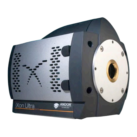
1.4.1 - Camera description The iXon Ultra camera is shown below. The camera has evolved from the iXon and iXon3 systems, with the introduction of a USB 2.0 interface instead of the previous proprietary interface and PCI card. The camera re-uses many of the strengths of the iXon3 including the high performance vacuum assembly and much of the camera triggering and control logic. -
Page 18: Camera Power Supply Unit
1.4.2 - Camera Power Supply Unit The iXon Ultra system is designed to be powered from an SW4189 external PSU (Andor P/N PS-90) as shown in Figure 2. This requires an AC mains input between 100-240 V, 47-63 Hz and a maximum supply current of 1.6 A. -
Page 19: Specifications
Weight (camera head only) 3.5 kg [7.8 lb] Specifications are subject to change without notice 1.6 - ACCESSORIES The following accessories are available for your iXon Ultra system: ANDOR PART NUMBER ITEM DESCRIPTION Optomask microscopy accessory, used to mask unwanted sensor area... -
Page 20: Safety Precautions And Maintenance
Ultra Introduction to iXon Ultra Hardware 1.7 - SAFETY PRECAUTIONS AND MAINTENANCE 1.7.1 - Care of the camera WARNINGS: The camera is a precision scientific instrument containing fragile components. Always handle with the care necessary for such instruments. There are no user serviceable parts inside the camera. If the head is opened the warranty will be void. -
Page 21: Regular Checks
Ultra Introduction to iXon Ultra Hardware 1.7.2 - Regular checks The state of the product should be checked regularly, especially the following: • The integrity of the enclosure • Any water hoses used • The AC/DC External Power Supply • The mains cable NOTE: Do not use equipment that is damaged. 1.7.3 - Annual electrical safety checks It is advisable to check the integrity of the insulation and protective earth of the product on an annual basis, e.g. -
Page 22: Working With Electronics
1.7.6 - Working with electronics The computer equipment that is to be used to operate the iXon Ultra should be fitted with appropriate surge/EMI/RFI protection on all power lines. Dedicated power lines or line isolation may be required for some extremely noisy sites. -
Page 23: Dew Point Graph
3: Dew point Graph For example, when using an iXon Ultra 897, you will need 10ºC cooling water to guarantee performance down to -100ºC In the relatively dry atmosphere of an air-conditioned lab, cooling water at 10ºC should not present any problems. -
Page 24: Em Gain Ageing
EM Gain fall-off over a period of time. It is important to note that this ageing effect applies to any EMCCD camera manufacturer that incorporates L3Vision sensors into their cameras. The Andor iXon Ultra 897 model uses an L3Vision sensor. -
Page 25: Minimizing Particulate Contamination
It is important that particulate contamination of the exterior of the camera window is kept to a minimum, such that images are kept free of ‘shadowing’ particles directly in the optical path. The iXon Ultra range comes equipped with an internal C-mount shutter. -
Page 26: Section 2: Installation
To connect the camera use the supplied power block to power the camera. A faint beep may be heard when the camera is turned on. Note: The iXon Ultra has a power switch on the camera head for convenience. Connect the supplied USB lead to the PC. (A USB socket on the rear of a desktop machine is preferred.) The supplied Multi i/o cable may be required depending on the measurement being carried out. -
Page 27: Installing Andor Solis Software - Windows O/S(Xp/Vista/Seven)
Ultra Installation 2.2 - INSTALLING ANDOR SOLIS SOFTWARE - WINDOWS O/S(XP/VISTA/SEVEN) Terminate and exit any programmes that are running on the PC. Insert the Andor CD. The InstallShield Wizard now starts. If it does not start automatically, run the file setup.exe directly from the CD then follow the on-screen prompts that then appear, e.g.:... - Page 28 Ultra Installation Select iXon Ultra as shown above then click Next> and the following dialog box appears: Click Next > (alternatively, click on Browse…, choose your own shortcut destination then click Next >). Select (or de-select) the additional tasks to be performed during the set-up, then click Next>:...
- Page 29 Ultra Installation Click Install to continue with the installation (or click <Back, if you want to review / change any settings. When Install is pressed an update progress bar will appear while the installation is performed, e.g. : 9. When the hardware installation has been completed, the following screen will appear:...
-
Page 30: New Hardware Wizard
Installation 2.3 - NEW HARDWARE WIZARD When the first iXon Ultra camera is connected to a PC for the first time, the Found New Hardware Wizard screen will appear, e.g.: Select the ‘No, not this time only’ option then click Next> and the following screen appears: Select the ‘Install from a list or specified location (Advanced)’... - Page 31 This is a feature of how Windows deals with the USB interface. On the first startup of Solis, you may be required to direct the software to the iXon Ultra drivers. If so, select the directory that Andor Solis was installed to.
-
Page 32: Connectors
Signal diagrams of these connections can be found on pages 93 & 94. The interfaces and internal circuits of the iXon Ultra are rated as SELV (Safety Extra Low Voltage), all interfacing equipment should use SELV voltage and current levels. -
Page 33: Water Pipe Connectors
2.5 - WATER PIPE CONNECTORS Two barbed coolant hose inserts are supplied as standard with the iXon Ultra camera, suitable for connection to 6 mm (0.25”) internal diameter soft PVC tubing / hose. The recommended tubing should have 10 mm (0.4”) outside diameter, i.e. -
Page 34: Mounting Posts
Ultra Installation 2.6 - MOUNTING POSTS • Mounting posts can be fitted on all four sides of the camera. These can be used to mount the camera if the C-Mount is not used, or to mount accessories. Note: A bag containing two Ø1/2" x 80 mm long x 1/4-20 UNC posts is included with all kits. • There are 4 pairs of holes for the mounting posts, each with 2.0" spacing. figure 6: mounting post installation... -
Page 35: Cooling
Ultra Installation 2.7 - COOLING For accurate readings, the EMCCD Sensor should first be cooled to a stable temperature. This will help reduce dark signal and associated shot noise. The Temperature Control Dialog is accessed via the Hardware…Temperature menu item or by double clicking on the... -
Page 36: Startup Dialog
2.8 - START-UP DIALOG On start-up of the Solis software a dialog will appear, offering a selection of cameras currently connected to your PC, e.g.: Highlight the Andor IXon Ultra camera and click OK to continue with the selected camera. Page 36... -
Page 37: Section 3 - Features And Functionality
Advances in sensor technology have led to the development of a new generation of ultra-sensitive, low-light Electron Multiplying Charged Coupled Devices (EMCCDs). At the heart of your iXon Ultra camera is the latest EMCCD, a revolutionary technology, capable of single photon detection. An EMCCD is a silicon-based semiconductor chip bearing a two-dimensional matrix of photo-sensors or pixels. - Page 38 Ultra Features and Functionality During an acquisition using a conventional Frame Transfer CCD (FT CCD), the image area is exposed to light and an image is captured. This image, in the form of an electronic charge, is then automatically shifted downwards behind the masked region of the chip before being read out.
-
Page 39: Em Gain And Read Noise
EM Gain. For example, an iXon Ultra 897 typically has a read noise of 50 electrons rms when reading out at 10MHz. This can easily be reduced to <... -
Page 40: Em Gain On Vs Em Gain Off
Multiplicative Noise, which has the effect of increasing the shot noise by a factor of √2 or ~1.41. figure 9: Signal to noise plots em Gain on vs. em Gain off for back-illuminated iXon ultra emccDs at 10mhz readout speed... - Page 41 ~42 photons/pixel, at which it is still advisable to read out through the EM amplifier with Gain applied. figure 10: em Gain on vs. conventional amplifier signal to noise plots for back-illuminated iXon ultra emccDs at 1mhz readout speed...
-
Page 42: Multiplicative Noise Factor And Photon Counting
Ultra Features and Functionality 3.1.4 - Multiplicative Noise Factor and Photon Counting It is impossible to know the exact gain a detected signal charge traversing the EM Gain register will acquire, due to the stochastic nature of the processes which produce EM Gain. However, it is possible to calculate the probability distribution function of output charge for a given input charge. - Page 43 Ultra Features and Functionality figure 11: Signal intensity profile Within the framework of less than 1 electron falling on a pixel in a single exposure, the EMCCD can be used in Photon Counting Mode. In this mode, a threshold is set above the ordinary amplifier readout and all events are counted as single photons.
-
Page 44: Em Gain Dependence And Stability
Ultra Features & Functionality 3.1.5 - EM Gain dependence and stability EM Gain is a function of the EM voltage and of the sensor operating temperature. When the user applies gain through the software, it is the EM voltage in the gain register that is varied. As can be seen from Figure 12 below, the dependence of EM Gain on EM voltage is sharp (note the logarithmic scaling). -
Page 45: Realgain Tm : Real And Linear Gain
EM Gain @ -50°C, or at -100°C gives the same x300 actual gain. This delivers a new benchmark of simplicity and ease of operation to the user, and sets a new precedent in what should be expected from EMCCD technology. Figure 14: realGain™ calibration in the iXon ultra – the same linear relationship holds across all cooling temperatures Page 45... -
Page 46: Em Gain Ageing: What Causes It And How Is It Countered
Try not to over-saturate the EMCCD detector. For simplicity and ease of use many of these guidelines have been uniquely woven into the iXon Ultra systems, to make it difficult for the user to step outside of them and unwaringly cause accelerated sensor ageing. This defence is two pronged, and makes heavy use of Andor’s linear and quantitative gain calibration scale (RealGain... -
Page 47: Gain And Signal Restrictions
Andor website for the latest EMCAL routine. This process uses the iXon Ultra in-built temperature compensated linear gain scales to reset the EM Gain calibration to reflect the true values requested on the software scale, in reality giving RealGain values and thus markedly prolonging the operational lifetime and quantitative reliability of the technology, and circumventing the need to return to the factory for recalibration. -
Page 48: Cooling
Chilling All Andor iXon Ultra systems support both cooling options. Irrespective of which method is being employed, it is not desirable for the operating temperature of the CCD simply to be dependent on, or vary with, the heat sink temperature. -
Page 49: Sensor Readout Optimization
Ultra Features and Functionality 3.3 - SENSOR READOUT OPTIMIZATION To allow the camera to be optimized for the widest range of applications, it is important to have flexibility in the readout options available. Some of these include: Cooling (please see page 48) •... -
Page 50: Sensor Pre-Amp Options
Ultra Features and Functionality 3.3.1 - Sensor Pre-amp options An EMCCD sensor can have a much larger dynamic range than can be faithfully reproduced with the Analogue/ Digital converters and signal processing circuitry currently available on the market. To overcome this shortcoming, and to access the range of signals from the smallest to the largest, as well as to optimize the camera performance, it is necessary to allow different pre-amplifier gain settings. -
Page 51: Variable Horizontal Readout Rate
Note: a Side effect of the new high speed ADC method chosen for the iXon Ultra, is that the full range of ADC codes 0- 65535 is not available. A margin has been added and the iXon will reach an ADC saturation that is lower than 65535. -
Page 52: Variable Vertical Shift Speed
There are a number of different horizontal readout rates available on the iXon Ultra model. Please refer to the performance sheet for readout rates available on your particular model. -
Page 53: Output Amplifier Selection
3.3.4 - Output amplifier selection The iXon Ultra camera incorporates dual output amplifiers, an electron multiplying output amplifier and a conventional output amplifier. This increases the versatility of the camera as the EM amplifier can be selected for fast imaging in low- light conditions, whilst the conventional amplifier can be selected where more light is available and a slower readout, with its associated lower read noise and higher dynamic range, is preferred. -
Page 54: Baseline Optimization
This is most often observed during long kinetic series. The iXon Ultra series employs a Baseline Clamp technique that holds the baseline to a predetermined level. Baseline Clamp corrects each individual image for any baseline drift by subtracting an average bias signal from each image pixel and then adding a fixed count level to ensure that the displayed signal level is always a positive number of counts. -
Page 55: Baseline Level In Crop Mode
When a Sub Image has been defined, only data from the selected pixels will be digitized. Data from the remaining pixels will be discarded. The flexible configuration of the iXon Ultra allows the user to set the Sub Image area to any size and location on the CCD chip. - Page 56 Ultra Features and Functionality Figure 17: Vertical and Horizontal binning of two rows Step 1 Charge is built up on the sensor. Step 2 Charge in the frame is shifted vertically by one row, so that the bottom row of charge moves down into the shift register.
-
Page 57: Acquisition Options
3.4.1 - Capture Sequence in Frame Transfer (FT) Mode A number of acquisition modes are available for the iXon Ultra range to best suit your experimental demands. In Frame Transfer (FT) acquisition mode, the iXon Ultra can deliver its fastest performance whilst maintaining optimal Signal to Noise. -
Page 58: Points To Consider When Using Ft Mode
Ultra Features and Functionality 3.4.1.1 - Points to consider when using FT Mode • In this mode, there are no Keep Clean Cycles between images during an accumulation or kinetics series as they are not necessary. • This mode gives the fastest way to continually take images; however, the minimum exposure time is restricted to the time taken to read out the image from the Storage area. • The accumulation cycle time and the kinetic cycle time are fully dependent on the exposure time and hence cannot be set via software. -
Page 59: Capture Sequence In Non-Frame Transfer Mode (Nft) With An Ft Ccd
Ultra Features and Functionality 3.4.2 - Capture Sequence in Non-Frame Transfer Mode (NFT) with an FT CCD It is also possible to operate an FT CCD in a Non-Frame Transfer (NFT) mode. In this mode of operation, an FT CCD acts much like a standard CCD. -
Page 60: Points To Note About Using An Ft Ccd As A Standard Ccd
Ultra Features and Functionality 3.4.2.1 - Points to note about using an FT CCD as a standard CCD • The exposure time, accumulation cycle time and the kinetic cycle time are independent. • The minimum exposure time is not related to the time taken to read out the image. • As the captured image is quickly shifted into the Storage area, even in NFT mode, the system can still be used without a mechanical shutter. • For short exposure times, the image may appear streaked as the time taken to shift the Image area into the Storage area and the exposure time may be of similar magnitude, but much less than a non-frame transfer. -
Page 61: Capture Sequence For Fast Kinetics With An Ft Ccd
Ultra Features and Functionality 3.4.3 - Capture Sequence for Fast Kinetics (FK) with an FT CCD Fast Kinetics (FK) is a special readout mode that uses the actual CCD as a temporary storage medium and allows an extremely fast sequence of images to be captured. The capture sequence is illustrated here:... -
Page 62: Keep Clean Cycles
3.4.4 - Keep Clean Cycles iXon Ultra cameras have a range of different Keep Clean Cycles that are run depending on the actual model and the state the camera is in. The first Keep Clean Cycle to be discussed is the one that runs while the camera is in an idle state, i.e. - Page 63 Ultra Features and Functionality The second type of Keep Clean Cycle is executed between individual scans in a kinetic series, and is relevant to Non- Frame Transfer Mode combined with either Internal or Software Trigger. It is called the Internal Keep Clean Cycle.
- Page 64 Ultra Features and Functionality The third Keep Clean is the External Keep Clean Cycle. This cycle uses a different sequence of horizontal and vertical clocking, as it must be able to respond to external events extremely rapidly but at the same time keep the Image area of the sensor charge free.
-
Page 65: Triggering Options
Features and Functionality 3.5 - TRIGGERING OPTIONS The iXon Ultra camera has several different triggering modes. These include Internal, External (and Fast External), External Start, External Exposure and Software Trigger. Note also that many of these features require iCam technology within the camera, fuller details of which can be viewed through www.andor.com •... -
Page 66: Triggering Options In Ft Mode
Ultra Features and Functionality 3.5.1 - Triggering options in Frame Transfer (FT) mode 3.5.1.1 - Internal Triggering (FT) This is the simplest mode of operation, in that the camera determines when the exposure happens. By monitoring the Fire output, the user can determine exactly when the camera is “exposing”. -
Page 67: External Triggering (Ft)
Ultra Features and Functionality 3.5.1.2 - External Triggering (FT) When the camera is idle, it is running the Idle Keep Clean Cycle described previously. On receipt of the Start command from the PC, the camera goes into its External Keep Clean Cycle. This cycle consists of one vertical followed by one horizontal shift, repeated continuously. - Page 68 Features and Functionality Since all iXon Ultra cameras have iCam technology, the rising edge of the external trigger can occur before the end of the previous read out, provided that the falling edge of the Fire pulse occurs after the readout has completed, i.e. the External Trigger is only accepted up to the ‘User Defined Delay Period’...
-
Page 69: External Exposure (Ft)
Ultra Features and Functionality 3.5.1.3 - External Exposure (FT) This mode is distinct from the triggering modes discussed previously, in that the exposure period is fully controlled by the width of the external trigger pulse. The exposure period starts on the positive edge and concludes on the negative edge. -
Page 70: Triggering Options In Nft Mode
Ultra Features and Functionality 3.5.2 - Triggering options in Non-Frame Transfer (NFT) mode 3.5.2.1 - Internal (NFT) When the camera is idle, i.e. not actively capturing images, it is repeatedly running the Idle Keep Clean Cycle. When the Start command is received from the PC, the camera will complete the current Keep Clean Cycle, and then perform sufficient vertical shifts to ensure the Image and Storage regions are completely free of charge. -
Page 71: External And Fast External (Nft)
Ultra Features and Functionality 3.5.2.2 - External & Fast External (NFT) In External Trigger modes, once an acquisition has been started, the camera is placed into the special clearing cycle called “External Trigger Keep Clean’, which was discussed previously. As can be seen from the figure below, the External Keep Clean Cycle runs continuously until the first external trigger event is detected;... -
Page 72: External Exposure (Nft)
Ultra Features and Functionality 3.5.2.3 - External Exposure (NFT) This mode is distinct from the triggering modes discussed previously, in that the exposure period is fully controlled by the width of the external trigger pulse. The exposure period starts on the positive edge and concludes on the negative edge. -
Page 73: Software Trigger (Nft)
Ultra Features and Functionality 3.5.2.4 - Software trigger (NFT) This mode is particularly useful when the user needs to control other equipment between each exposure and does not know in advance how long such control will take, or if the time taken changes randomly. With Software Trigger, the camera and software are in a high state of readiness and can react extremely quickly to a trigger event issued via software. -
Page 74: Trigger Options In Fast Kinetics (Fk) Mode
Ultra Features and Functionality 3.5.3 - Trigger options in Fast Kinetics (FK) mode 3.5.3.1 - Internal (FK) As Fast Kinetics uses both the Image and Storage areas as temporary storage areas, the number of options available is quite limited. The simplest mode is again Internal Trigger and, as with the internal trigger modes described previously, the system determines when the acquisition begins and then uses the exposure time defined by the user. -
Page 75: External (Fk)
Ultra Features and Functionality 3.5.3.2 - External (FK) In External Trigger mode, a trigger pulse is required to start each scan in the series. The rising edge of the trigger defines the trigger event. The user can delay the start of the vertical shifting relative to the trigger event. After the delay has elapsed, the number of rows (as specified by the user) are vertically shifted. -
Page 76: External Start (Fk)
Ultra Features and Functionality 3.5.3.3 - External Start (FK) External Start trigger mode is a combination of External and Internal Trigger. At the start of the capture process, the camera is running the External Keep Clean Cycle waiting for a trigger pulse to be applied to the External Trigger input. - Page 77 3.6 - SHUTTERING The iXon Ultra camera is supplied with a built in bi-stable shutter. This bi-stable shutter requires no power to maintain the open or closed state - so it is well suited to long exposures. The bi-stable shutter also has a longer theoretical life because of the lower energy levels used.
- Page 78 3.7 - COUNT CONVERT One of the distinctive features of the iXon Ultra is the capability to quantitatively capture and present data in units of electrons or photons; the conversion applied either in real time or as a post-conversion step. Photons that are incident on pixels of an array detector are captured and converted to electrons.
- Page 79 Ultra. The control architecture of the iXon Ultra is extremely tuneable, meaning the camera can be adapted and optimized for a wide variety of quantitative experimental requirements, ranging from fast single photon counting through to slower scan, 16-bit dynamic range measurements.
- Page 80 Ultra Features and Functionality 3.8.1 - OptAcquire modes Pre-defined OptAcquire modes include: Optimized for capturing weak signal at fast frame rates with single photon Sensitivity and Speed (EM Amplifier) sensitivity. Suited to the majority of EMCCD applications. Dynamic Range and Speed...
- Page 81 If an experiment demands fast temporal resolution but cannot be constrained by the maximum storage size of the sensor (as is the case for ‘Fast Kinetics Mode’ of readout), then it is possible to readout the iXon Ultra in ‘Cropped Sensor Mode’.
- Page 82 Andor iXon Ultra 897 EMCCD camera, has demonstrated that Cropped Sensor Mode, in conjunction with binning, pushed the speed beyond 4,000 frames per second. The table below shows the Imaging frame rate potential of the Andor iXon Ultra 897 EMCCD camera under conditions of Cropped Sensor Mode readout:...
- Page 83 Key Fact – To successfully photon count with EMCCDs, there has to be a significantly higher probability of seeing a ‘photon spike’ than seeing a dark current / CIC ‘noise spike’. The iXon Ultra 897 has the lowest dark current / CIC performance on the market, yielding both lower detection limits and higher contrast images.
- Page 84 Ultra Features and Functionality To successfully photon count with EMCCDs, there has to be a significantly higher probability of seeing a ‘photon spike’ than of seeing a dark current / CIC ‘noise spike’. The lower the contribution of this ‘spurious’ noise source to a single...
- Page 85 Ultra Features and Functionality 3.10.1 - Photon Counting by Post-Processing As a post-processing analysis, the user holds the flexibility to ‘trial and error’ photon counting a pre-recorded kinetic series, trading-off temporal resolution vs SNR by choosing how many images should contribute to each photon counted accumulated image.
- Page 86 This is realized through the new Spurious Noise Filter (SNF) functionality of iXon Ultra, which offers the user a choice of advanced algorithms to try. SNF can be applied either in real time or as a post-processing step. Like the count convert option, the real time processing of the filters is performed in hardware, thereby providing minimal impact on the display rate.
-
Page 87: Section 4: Hardware
EMCCD technology, sometimes known as “on-chip multiplication”, is an innovation first introduced to the digital scientific imaging community by Andor Technology in 2000, with the launch of our dedicated, high-end iXon platform of ultra-sensitive cameras. Essentially, the EMCCD is an image sensor that is capable of detecting single photon events without an image intensifier (achievable by way of a unique electron multiplying structure built into the chip). - Page 88 4.1.5 - What is Andor Technology's experience with EMCCDs? Andor Technology was the first company to introduce an EMCCD based detector in 2000. Since then the company has led the way in the development of EMCCD detectors, introducing the first back illuminated EMCCD in January 2003.
- Page 89 The Andor iXon Ultra is the best camera on the market for minimizing such smear, as the vertical clock speeds can be tuned via the software to deliver the fastest parallel shifts in the industry, which has the further advantage of faster overall frame rates (especially when using sub-array and/or pixel binning readout options).
- Page 90 Ultra Hardware 4.3 - VACUUM HOUSING Unless protected, cooled CCD sensors will condense moisture, hydrocarbons and other gas contaminants that will attack the CCD surface. If that happens, CCD performance will decline proportionally and will eventually fail. Fortunately, the integrity of the sensor can be preserved by housing it in a protective enclosure. However, it is important to understand that all such environments are not the same and the underlying technology used can seriously impact camera life (and performance).
-
Page 91: Thermoelectric Cooler
Heat must be efficiently dissipated from the TE cooler for effective cooling of the sensor. The iXon Ultra is expertly designed to yield maximum heat dissipation, via either forced air cooling (in-built fan) or water cooling which, in combination with Andor’s UltraVac... -
Page 92: Usb 2.0 Interface
The iXon Ultra automatically switches from 16 bit to 32 bit transfer mode – when running with real time count convert active for example. This happens seamlessly under software control, and is needed because, in count convert mode, the number of electrons/photons detected can be >... - Page 93 4.6 - EXTERNAL I/O To enable additional functionality, the 4 x SMB connectors and Fischer connector from the iXon3 have been replaced with a 26 way high density D-type connector. figure 41: iXon ultra io connector Pinout for D-Type connector External Trigger...
-
Page 94: Signal Diagrams
Ultra Hardware 4.7 - SIGNAL DIAGRAMS iXon Ultra Input & Output Timing Hardware figure 41: external Trigger External Trigger Input (at connector) • VIH (High level input voltage, minimum) = 2.2V • VIL (Low level input voltage, maximum) = 0.88V • Change to falling edge trigger by connecting “Trigger Invert Input” pin to Ground with ≤ 500Ω figure 42: fire & Shutter Fire, Shutter, Arm & Frame Output (at connector) •... -
Page 95: Section 5: Troubleshooting
Ultra Troubleshooting SECTION 5: TROUBLESHOOTING 5.1 - UNIT DOES NOT SWITCH ON • Check power cord is plugged in and connected correctly to mains supply If applicable, replace fuse in the supplied mains cable as detailed in page 21 • • If the unit still does not switch on after the checks above have been carried out, contact Andor Technical Support 5.2 - SUPPORT DEVICE NOT RECOGNISED WHEN PLUGGED INTO PC • Choose another USB port • If this is unsuccessful review “Use of Multiple high speed USB 2.0 I/O on one camera” in the trouble shooting guide. 5.3 - TEMPERATURE TRIP ALARM SOUNDS (CONTINUOUS TONE) To protect the camera from overheating, a thermal switch has been attached to the heat sink. - Page 96 USB rate from a Clara/iXon Ultra (assuming there is sufficient RAM, CPU etc to process the data). If the machine has only one EHC it may not be possible to operate a Clara/iXon Ultra and any other devices that require significant USB bandwidth.
- Page 97 Ultra Troubleshooting To map each port, use a High Bandwidth device such as a modern USB memory stick. High bandwidth devices will only appear in an EHC section, as shown below, where one can see the USB mass storage device under “Enhanced Host Controller - 3A6A”.
- Page 98 Ultra Appendix A.1 - GLOSSARY If this is the first time you have used Andor’s EMCCD, the glossary that follows will help you to familiarize yourself with its design philosophy and some of its key terminology. A.1.1 - Readout sequence of an EMCCD In the course of readout, charge is moved vertically into the shift register then horizontally from the shift register into the output node of the amplifier.
- Page 99 Ultra Appendix A.1.2 - Accumulation Accumulation is the process by which data that have been acquired from a number of similar scans are added together in computer memory. This results in improved signal to noise ratio. A.1.3 - Acquisition An Acquisition is taken to be the complete data capture process.
-
Page 100: Detection Limit
Ultra Appendix A.1.9 - Detection Limit The Detection Limit is a measure of the smallest signal that can be detected in a single readout. The smallest signal is defined as the signal whose level is equal to the noise accompanying that signal, i.e. a Signal to Noise ratio (S/N) of unity. -
Page 101: Readout Noise
Ultra Appendix The Pixel Noise is the variation in the pixel’s charge level when exposed to a constant signal flux over a significantly valid period of read levels. The pixel noise is normally expressed as the value of the Root Mean Square (rms) of these variations. - Page 102 Ultra Appendix A.1.12.2 - Fixed Pattern Noise Fixed Pattern Noise (FPN) consists of the differences in count values read out from individual pixels, even if no light is falling on the detector. These differences remain constant from read to read. The differences are due in part to a variation in the dark signal produced by each pixel, and in part to small irregularities that arise during the fabrication of the CCD and in part to settling time of the electronics.
-
Page 103: Shift Register
Ultra Appendix A.1.17 - Shift Register The Shift Register usually consists of a single row of elements (or pixels) running parallel to, and below, the bottom row of light-gathering pixels (the image area) on the CCD-chip. The shift register is protected from light by an aluminium mask. - Page 104 Ultra Appendix B - MECHANICAL DIMENSIONS Page 104...
-
Page 105: C - Declaration Of Conformity
Ultra Appendix C - DECLARATION OF CONFORMITY Page 105... - Page 106 Ultra Appendix Page 106...
-
Page 107: Service Description
Ultra Appendix D - HARDWARE AND SOFTWARE WARRANTY SERVICE D.1 - SERVICE DESCRIPTION D.1.1 The Andor Repair service provides a repair and return service for defective products supplied by Andor under a supply contract. Using this service, the original ,defective part sent in by the Customer will be, where possible, returned after repair or will be replaced. - Page 108 Ultra Appendix D.3 - Hardware Remediation D.3.1 If the issue cannot be resolved remotely and a fault has been diagnosed, a Return Materials Authorization (“RMA”) number will be issued. This RMA number will be valid for 30 days from the date of issue. An RMA number must be obtained from Andor prior to the return of any material.
- Page 109 Ultra Appendix D.4 - Software Remediation D.4.1 During Warranty Customers have access to the Service Desk at www.andor.com/contact_us/support_request to report product defects. A Customer who has purchased their product via a reseller or third party and who believes they have a software warranty defect should in the first instance contact a representative of their seller’s product support team.
Need help?
Do you have a question about the iXon Ultra and is the answer not in the manual?
Questions and answers