Table of Contents
Advertisement
Advertisement
Table of Contents

Related Manuals for dbx 566


Summary of Contents for dbx 566
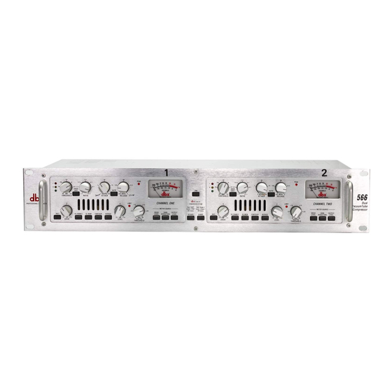
- Page 1 Dual Vacuum Tube Compressor Owner’s Manual Version 1.0...
-
Page 2: Declaration Of Conformity
Operation of this unit within significant electromagnetic fields should be avoided. ¥ use only shielded interconnecting cables. DECLARATION OF CONFORMITY ManufacturerÕs Name: ManufacturerÕs Address: declares that the product: dbx 566 BROWN - Live conforms to the following Product Specifications: Safety: EMC: Supplementary Information:... -
Page 3: Table Of Contents
Table of Contents Introduction ...2 Features...2 Inspection ...2 Warranty...3 Connections...4 Compressor Controls ...5 Rear Panel...10 Specifications ...11 Settings Page...13... -
Page 4: Introduction
To ensure years of trouble- free operation, each dbx 566 must pass a rigorous set of performance tests and a 24-hour burn-in peri- od before it is shipped from the factory. -
Page 5: Warranty
Warranty This warranty is valid only for the original purchaser and only in the United States. We warrant dbx products against defects in materials or workmanship for a period of two years from the date of orig- inal purchase for use, and agree to repair or, at our option, replace any defective item, except exter- nal power transformers, without charge for either parts or labor. -
Page 6: Connections
¥ Turn off all equipment before making any connections. ¥ Mount the 566 in a rack with the rack screws provided. The 566 can be mounted above or below anything that does not generate excessive heat. Ambient temperatures should not exceed 95¡F (35¡C) when equipment is in use. -
Page 7: Compressor Controls
Compressor Controls Figure 2: Front Panel Controls + 0 - THRESHOLD leds: ¨ The Ò+Ó led illuminates when the signal is above the OverEasy portion of the compression curve ¨ and that the full compression ratio is in effect . If OverEasy is disabled, this led indicates that the signal is above the level set by the Compressor Threshold control and that compression is occuring. - Page 8 ATTACK control: This control sets the amount of time it takes the 566 to begin compressing a signal once the detector has sensed a signal above the threshold. The attack range is from 3 dB/msec for a tighter and more noticeable compression effect with very little overshoot to .04 dB/msec for a more gradual compres-...
- Page 9 Compressor. SC (SIDECHAIN) ENABLE switch This switch enables the Sidechain processing loop. The Sidechain in and out connectors on the 566 rear panel allow external processing of the CompressorÕs detector signal. This switch has no effect if there is nothing plugged into the Sidechain loop even though the switch will light when pressed.
- Page 10 This configures the meter to show the output signal level. This works in conjunction with the output level assignment switch on the back of the 566. When the rear switch is set to +4 dBu, a meter read- ing of 0 VU corresponds to +4 dBu output. When the rear switch is set to -10 dBV, a meter reading of 0 VU corresponds to -10 dBV output.
- Page 11 DITHER switch ª This switch becomes active only when the optional dbx Conversion System digital output TYPE IV ª module is installed. Refer to the manual for the Conversion System for a description of the TYPE IV function of this switch. SHAPE switch ª...
-
Page 12: Rear Panel
Both XLR and TRS 1/4Ó connectors are provided for connecting either balanced or unbalanced line- level devices to the 566. The nominal output level can be set to either +4 dBu or -10 dBV with the +4 dBu/-10 dBV switch. -
Page 13: Specifications
Specifications COMPRESSOR Threshold Range: Ratio: Threshold Characteristic: Attack/Release Characteristic: Attack/Release Modes: Manual Attack Time: Manual Release Time: Auto Attack Time: Auto Release Time: Output Gain: LIMITER Type: Threshold Range: Ratio: Attack Time: Release Time: SYSTEM PERFORMANCE DRIVE Control Range: LEVEL Control Range: 0.5 dB Bandwidth: Frequency Response: THD + Noise:... - Page 14 Specifications Specifications (cont.) Power Consumption: Fuse: Mains Connection: PHYSICAL: Dimensions: Weight: Shipping Weight: Note: 0 dBu = 0.775V RMS. Specifications subject to change without notice. 30 Watts max. 100/120V: 500mA 250V Slow Blow 5mm X 20mm 230/240V: T250 mA 250V 5mm X 20mm IEC 320 Receptacle 3.5ÓH X 19ÓW X 8ÓD 12 lbs (5.5 kg)
-
Page 15: Settings Page
Photocopy this page and mark the settings you use for your sessions. Session: Comments: Session: Comments: dbx 566 Settings Page Date: Date:... - Page 16 8760 South Sandy Pkwy. Sandy, Utah 84070 Phone: (801) 568-7660 Fax: (801) 568-7662 IntÕl Fax: (603) 672-4246 Questions or comments? E¥mail us at: customer@dbxpro.com or visit our World Wide Web home page at: www.dbxpro.com...
Need help?
Do you have a question about the 566 and is the answer not in the manual?
Questions and answers