
Related Manuals for aosu T8210

Summary of Contents for aosu T8210
- Page 1 Video Doorbell and Wi-Fi HomeBase (Battery or Hardwired Doorbell) Quick Start Guide...
- Page 3 TABLE OF CONTENTS English Deutsch Français Español Italiano にほんご P121...
- Page 4 TABLE OF CONTENTS What's Included Product Overview P03-P04 How The System Works App Installation and System Setup Video Doorbell Installation P07-P20 Notice P21-P23 Customer Service Please download the "aosu"App and then add devices before installing doorbell.
-
Page 5: What's Included
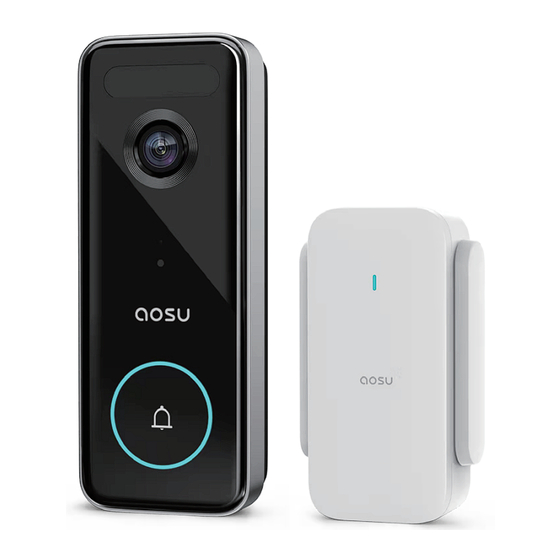
What's Included What's Included Video Doorbell Mounting Bracket Screw Hole Positioning-Card 15° Mounting Wi-Fi HomeBase Phillips-Head Wedge (Optional) Screwdriver USB-C Charging Extension Wires and Screw Packs Cable Wire Nuts (Optional) Wi-Fi HomeBase Quick Start Guide Doorbell Detaching Pin Power Pin... -
Page 6: Product Overview
Product Overview Video Doorbell (Battery or Hardwired) Motion Sensor Camera Lens Microphone Ambient Light Sensor Doorbell Circular Light Doorbell Button Speaker SYNC Button Power Terminals for Existing Doorbell Wire (Optional) Detaching Mechanism USB-C Charging Port... - Page 7 Wi-Fi HomeBase SYNC Button Status LED Speaker Power Pin Operation How-to Power on the doorbell Press and release the SYNC button Power off the doorbell Press and hold the SYNC button for 3 seconds. Reset the doorbell Press and hold the SYNC button for 10 seconds. Connect to Wi-Fi network Press and hold the SYNC button until you hear a beep...
-
Page 8: How The System Works
How The System Works What’s Required for Installation Phillips-Head Screwdriver Power Drill with 1/4" (6.35mm) Drill Bit How the System Works The video doorbell system includes 2 parts. One is the video doorbell at your door. The other is the Wi-Fi HomeBase in your house. The video doorbell detects motion at your porch and allows you to answer the door anytime and anywhere. - Page 9 1. Download the aosu App from the App Store (iOS devices) or Google Play (Android devices). 2. Scan the QR code below or search "aosu" in the App Store or Google Play. Register or log into the App. Add Video Doorbell V8S and scan the QR code...
- Page 10 Video Doorbell Installation Choose The Power Option Option 1 - Battery Powered 1. If you don’t have existing doorbell wiring at the front door, please use the built-in battery. You are free to determine the doorbell position and the mounting is easy and quick. 2.
-
Page 11: Option 1 - Battery Powered
Option 1 - Battery Powered Step 1 Find a Mounting Spot Take the video doorbell to your front door and check the live view on the App at the same time. Find a location where you can get the desired field of view. -
Page 12: Step 2 Mounting The Bracket
Step 2 Mounting the Bracket Mount the Doorbell on a Wooden Surface If you mount the doorbell on a wooden surface, you don’t need to pre-drill pilot holes. Use the provided screws to secure the Mounting Bracket on the wall. The Screw Hole Positioning Card indicates the position of the screw holes. - Page 13 Step 3 Mounting the Doorbell Mount the Doorbell Align the doorbell on top and then snap it on the bottom. Press it down until it clicks into place. You’re all set! If you want to detach the doorbell or recharge it, please refer to the following sections.
- Page 14 Detach the Doorbell 1. Use the doorbell detaching pin provided if you wish to detach the doorbell from the Mounting Bracket. 2. Press and hold the hole on the bottom of the doorbell and then lift its bottom to take it off. What is required: Doorbell Detaching Pin...
- Page 15 Recharge the Doorbell USB-C Charging: The blue light flashes LED indication Fully charged: Solid blue Charging time 6 hours from 0% to 100%...
- Page 16 Option 2 - Doorbell Wire Powered 1. If you have existing and working doorbell wiring at the front door, the doorbell will be powered by the wires constantly. So you don’t need to detach and charge it after installation. 2. Since the doorbell is connected to the wires, the mounting position is limited.
- Page 17 Step 1 Verify whether the doorbell wires are working 1. Ring the existing doorbell to check if it is working. If the doorbell doesn’t ring, your doorbell wires may be defective. Power the doorbell on its own battery or consult an electrician to fix the wires. 2.
- Page 18 Step 2 Detach the Existing Doorbell Button If you already have existing doorbell wiring: 1. Remove the existing doorbell button with a Phillips-Head screwdriver. 2. Pull the two wires out carefully when removing the existing doorbell. Straighten the wire ends if necessary. What is required: Phillips-Head Screwdriver...
- Page 19 Step 3 Find a Mounting Spot 1. Determine the mounting position of the doorbell. Consider the factors below: • Check if you can reuse the existing holes and anchors on the wall or door frame. • If you drill the mounting holes for the first time, the recommended mounting height is 48"...
- Page 20 Step 4 Mount the Bracket If you mount the doorbell on a wooden surface, you don’t need to pre-drill pilot holes. Use the provided screws to secure the Mounting Bracket on the wall. The Screw Hole Positioning Card indicates the position of the screw holes.
- Page 21 If you mount the doorbell on a surface made out of hard materials, like brick, concrete, stucco: • Drill 2 holes through the Screw Hole Positioning Card with 15/64”(6mm) drill bit. • Insert the provided anchors, and then use the provided long screws to secure the Mounting Bracket on the wall.
- Page 22 • If the wires are too short, use the extension wires and wire nuts provided to make them longer. Use electrical wiring tape instead if there is no more space on the wall for wire nuts. What is required: Extension Wires and Video Doorbell 2K Phillips-Head Wire Nuts (Optional) (Wired) Screwdriver Model:T8210...
- Page 23 Step 6 Mount the Doorbell on the Bracket Align the doorbell on top and then snap it on the bottom. Step 7 Restore Power Switch the master circuit breaker back to ON. You’re all set!
-
Page 24: Fcc Radio Frequency Exposure Statement
Notice FCC Statement This device complies with Part 15 of the FCC Rules. Operation is subject to the following two conditions: (1) this device may not cause harmful interference, and (2) this device must accept any interference received, including interference that may cause undesired operation. Warning: Changes or modifications not expressly approved by the party responsible for compliance could void the user's authority to operate the equipment. -
Page 25: Declaration Of Conformity
This product complies with the radio interference requirements of the European Community. Declaration of Conformity Hereby, Glazero Limited declares that this device is in compliance with the essential requirements and other relevant provisions of Directive 2014/53/EU. For the declaration of conformity, visit the Web site:https://www.aosulife.com/. -
Page 26: Battery Warning
This product is designed and manufactured with high quality materials and components, which can be recycled and reused. This symbol means the product must not be discarded as household waste, and should be delivered to an appropriate collection facility for recycling. Proper disposal and recycling helps protect natural resources, human health and the environment. -
Page 27: Customer Service
Customer Service Warranty 12-month limited warranty(The actual warranty period shall be implemented according to the requirements of local laws and regulations) Email Us Customer Support: support@aosulife.com Call Us United States: 1-866-905-9950 Mon-Fri 9AM-5PM United Kingdom: +44 20 3885 0830 Mon-Fri 9AM-5PM(GMT) Germany: +49 32 221094692 Mon-Fri 9:00-17:00 Facebook:@aosulife Twitter:@aosulife... -
Page 28: Table Of Contents
Inhaltsverzeichnis Was ist inbegriffen Produktübersicht P27-P28 So funktioniert das System App-Installation und Systemeinrichtung Installation der Video-Türklingel P31-P44 Hinweis P45-P47 Kundendienst Bitte laden Sie die „aosu“ App herunter und fügen Sie dann Geräte hinzu, bevor Sie die Türklingel installieren. -
Page 29: Was Ist Inbegriffen
Was ist inbegri en Video-Türklingel Montagehalterung Schraubenloch Positionierungskarte 15° Montagekeil WLAN HomeBase Kreuzschlitz (optional) schraubendreher USB-C-Kabel Verlängerungsdrähte Türklingel und Drahtmuttern Schraubenpakete (optional) WLAN HomeBase Einfache Anleitung Entfernungsstift Power-Pin... -
Page 30: Produktübersicht
Produktübersicht Video-Türklingel (Batterie oder festverdrahtet) Bewegungssensor Kameraobjektiv Mikrofon Umgebungslichtsensor Türklingel Kreis-Licht Türklingeltaste Lautsprecher SYNC-Taste Stromanschlüsse für vorhandenes Türklingelkabel (Optional) Ablösemechanismus USB-C Aufladestation... - Page 31 WLAN HomeBase SYNC-Taste Statu-LED Lautsprecher Power-Pin Betrieb So funktioniert es Türklingel einschalten SYNC-Taste drücken und loslassen Türklingel ausschlaten SYNC-Taste 3 Sekunden lang gedrückt halten Türklingel zurücksetzen SYNC-Taste 10 Sekunden lang gedrückt halten Mit WLAN verbinden SYNC-Taste gedrückt halten, bis Sie einen Piepton hören...
-
Page 32: So Funktioniert Das System
So funktioniert das System Was ist für die Installation erforderlich Kreuzschlitzschraubendreher Bohrmaschine mit 1/4" (6,35 mm) Bohrer So funktioniert das System Das Video-Türklingelsystem besteht aus 2 Teilen. Eine davon ist die Video-Türklingel an Ihrer Tür. Das andere ist die WLAN HomeBase in Ihrem Haus. Die Video-Türklingel erkennt Bewegungen auf Ihrer Veranda und ermöglicht es Ihnen, die Tür jederzeit und überall zu öffnen. - Page 33 App-Installation und Einrichtung des Systems 1.Laden Sie die „aosu“ App aus dem AppStore (IOS-Geräte) oder Google Play (Android-Geräte) herunter. 2.Scannen Sie den untenstehenden QR-Code oder suchen Sie im App Store oder bei Google Play nach „aosu“. Registrieren Sie sich oder loggen Sie sich in die App ein. Fügen Sie Video Türklingel V8S hinzu und scannen Sie den QR-Code für den späteren...
-
Page 34: Installation Der Video-Türklingel
Installation der Video-Türklingel Wählen Sie die Power-Option Option 1 - Batteriebetrieben 1.Wenn Sie keine vorhandene Türklingelverkabelung an der Haustür haben, verwenden Sie bitte den eingebauten Akku. Die Position der Türklingel können Sie frei bestimmen und die Montage ist einfach und schnell. - Page 35 Option 1 - Batteriebetrieben Schritt 1 Finden Sie einen Montagepunkt Nehmen Sie die Video-Türklingel mit vor Ihre Haustür und prüfen Sie gleichzeitig die Live-Ansicht in der App. Suchen Sie einen Ort, an dem Siedas gewünschte Sichtfeld erhalten. Berücksichtigen Sie die folgenden Faktoren: 1.Überprüfen Sie, ob Sie die vorhandenen Löcher und Anker an der Wand oder dem Türrahmen wiederverwenden können.
- Page 36 Schritt 2 Montage der Halterung Montieren Sie die Türklingel auf einer Holzoberfläche Wenn Sie die Türklingel auf einer Holzoberfläche montieren, müssen Sie keine Pilotlöcher vorbohren. Verwenden Sie die mitgelieferten Schrauben, um die Montagehalterung an der Wand zu befestigen. Die Positionskarte für Schraubenlöcher zeigt die Position der Schraubenlöcher an. Ohne 15°...
- Page 37 Schritt 3 Türklingel montieren Montage der Türklingel Richten Sie die Türklingel oben aus und rasten Sie sie unten ein. Drücken Sie es nach unten, bis es einrastet. Sie sind fertig! Wenn Sie die Türklingel abnehmen oder aufladen möchten, lesen Sie bitte die folgenden Abschnitte.
- Page 38 Abnehmen der Türklingel 1.Verwenden Sie den mitgelieferten Türklingel-Entfernungsstift, wenn Sie die Türklingel von der Halterung abnehmen möchten. 2.Halten Sie das Loch an der Unterseite der Türklingel gedrückt und heben Sie dann die Unterseite an, um sie abzunehmen. Was wird benötigt: Türklingel -Entfernungsstift...
- Page 39 Aufladen Ihrer Türklingel USB-C Aufladen: Das blaue Licht blinkt LED-Anzeige Voll aufgeladen:Solid blau Ladezeit 6 Stunden Von 0% bis 100%...
- Page 40 Option 2 – Stromversorgung über Türklingelkabel 1.Wenn Sie eine vorhandene und funktionierende Türklingelverkabelung an der Haustür haben, wird die Türklingel ständig über die Kabel mit Strom versorgt. Sie müssen es also nach der Installation nicht abnehmen und aufladen. 2. Da die Türklingel mit den Drähten verbunden ist, ist die Montageposition begrenzt.
- Page 41 Schritt 1 Überprüfen Sie, ob die Kabel der Türklingel funktionieren 1.Rufen Sie die vorhandene Türklingel an, um zu überprüfen, ob sie funktioniert. Wenn die Türklingel nicht klingelt, sind möglicherweise die Kabel der Türklingel defekt. Versorgen Sie die Türklingel mit ihrer eigenen Batterie oder wenden Sie sich an einen Elektriker, um die Kabel zu reparieren.
- Page 42 Schritt 2 Entfernen Sie die vorhandene Türklingeltaste Wenn Sie bereits über eine vorhandene Türklingelverkabelung verfügen: 1.Entfernen Sie die vorhandene Türklingeltaste mit einem Kreuzschlitzschraubendreher. 2.Ziehen Sie die beiden Kabel vorsichtig heraus, wenn Sie die vorhandene Türklingel entfernen. Richten Sie die Drahtenden ggf. gerade. Was wird benötigt: Kreuzschlitzsc- hraubendreher...
- Page 43 Schritt 3 Finden Sie einen Montagepunkt 1.Bestimmen Sie die Montageposition der Türklingel. Berücksichtigen Sie die folgendenFaktoren: • Überprüfen Sie, ob Sie die vorhandenen Löcher und Anker an der Wand oder dem Türrahmen wiederverwenden können. • Wenn Sie die Montagelöcher zum ersten Mal bohren, beträgt die empfohleneMontagehöhe 1,2 m über dem Boden.
- Page 44 Schritt 4 Montieren Sie die Halterung Wenn Sie die Türklingel auf einer Holzoberfläche montieren, müssen Sie keine Pilotlöcher vorbohren. Verwenden Sie die mitgelieferten Schrauben, um die Montagehalterung an der Wand zu befestigen. Die Positionskarte für Schraubenlöcher zeigt die Position der Schraubenlöcher an.
- Page 45 Wenn Sie die Türklingel auf einer Oberfläche aus harten Materialien wie Ziegel, Beton, Stuck montieren: •Bohren Sie 2 Löcher durch die Schraubenloch-Positionierungskarte mit einem 15/64” (6 mm) Bohrer. •Setzen Sie die mitgelieferten Dübel ein und verwenden Sie dann die mitgelieferten langen Schrauben, um die Montagehalterung an der Wand zu befestigen.
- Page 46 •Wenn die Drähte zu kurz sind, verwenden Sie die mitgelieferten Verlängerungsdrähte und Drahtmuttern, um sie zu verlängern. Verwenden Sie stattdessen Elektrokabelband, wenn an der Wand kein Platz mehr für Drahtmuttern ist. Was wird benötigt: Verlängerungsdrähte VideoTürklingel2K Kreuzschlitzschraub und Drahtmuttern (verdrahtet) Model: endreherr (optional) T8210...
- Page 47 Schritt 6 Montieren Sie die Türklingel an der Halterung Richten Sie die Türklingel oben aus und rasten Sie sie unten ein. Schritt 7 Stromversorgung wiederherstellen Schalten Sie den Hauptschalter wieder auf AN. Sie sind fertig!
-
Page 48: Hinweis
Hinweis FCC-Erklärung Dieses Gerät entspricht Teil 15 der FCC-Bestimmungen. Der Betrieb unterliegt den folgenden zwei Bedingungen: (1) Dieses Gerät darf keine schädlichen Störungen verursachen und (2) dieses Gerät muss alle empfangenen Störungen akzeptieren, einschließlich Störungen, die einen unerwünschten Betrieb verursachen können. Warnung: Änderungen oder Modifikationen, die nicht ausdrücklich von der für die Konformität verantwortlichen Partei genehmigt wurden, können die Berechtigung des Benutzers zum Betrieb des Geräts erlöschen... - Page 49 Dieses Produkt entspricht den Funkstörungen der Europäischen Gemeinschaft. Konformitätserklärung Hiermit erklärt Glazero Limited, dass dieses Gerät den grundlegenden Anforderungen und anderen relevanten Bestimmungen der Richtlinie 2014/53/EU entspricht. Die Konformitätserklärung finden Sie auf der Website:https://www.aosulife.com/. Dieses Produkt kann in allen EU-Mitgliedstaaten verwendet werden. Verwenden Sie das Gerät nicht in einer Umgebung mit zu hohen oder zu niedrigen Temperaturen, setzen Sie das Gerät niemals starker Sonneneinstrahlung oder einer zu nassen Umgebung aus.
- Page 50 Dieses Produkt wurde mit hochwertigen Materialien und Komponenten entwickelt und hergestellt, die recycelt und wiederverwendet werden können. Dieses Symbol bedeutet, dass das Produkt nicht als Hausmüll entsorgt werden darf und einer geeigneten Sammelstelle zum Recycling zugeführt werden muss. Eine fachgerechte Entsorgung und Wiederverwertung trägt zum Schutz der natürlichen Ressourcen, der menschlichen Gesundheit und der Umwelt bei.
-
Page 51: Kundendienst
Kundendienst Garantie 12 Monate eingeschränkte Garantie (Der tatsächliche Garantiezeitraum wird gemäß den Anforderungen der lokalen Gesetze und Vorschriften umgesetzt) Schreiben Sie uns eine E-Mail Kundensupport: support@aosulife.com Rufen Sie uns an US: 1-866-905-9950 Mo-Fr 9-17 Uhr UK: +44 20 3885 0830 Mo-Fr 9-17 Uhr (GMT) DE: +49 32 221094692 Mo-Fr 9:00-17:00 Facebook: @aosulife Twitter: @aosulife... - Page 52 TABLE DES MATIÈRES Ce qui est inclus Description du produit P51-P52 Comment fonctionne le système Installation de l'application et configuration dusystème Installation de sonnette vidéo P55-P68 Notification P69-P71 Service Clients Avant d'installer la sonnette, veuillez télécharger l'application "aosu" et ajouter l'appareil...
-
Page 53: Ce Qui Est Inclus
Ce qui est inclus Sonnette vidéo Support de montage Plaque de positionnement des trous de vis Cale de montage Base de réception PhillipsHead 15° (facultatif) Wi-Fi Tournevis Câble de charge Rallonges et écrous Paquets de vis USB-C (facultatif) Pin d'alimentation Guide de Goupille de de la Base de... -
Page 54: Description Du Produit
Description du produit Sonnette vidéo (à batterie ou filaire) Capteur de mouvement Objectif de la caméra Microphone Capteur de lumière ambiante Lumière circulaire de sonnette Bouton de sonnette Haut-parleur Bouton SYNC Bornes d'alimentation pour les fils de sonnette existants (facultatif) Mécanisme de Port de chargement USB-C détachement... - Page 55 Base de réception Wi-Fi Bouton SYNC LED d'état Haut-parleur Pin d'alimentation Opération Commen Allumer la sonnette Appuyez et relâchez le bouton SYNC Appuyez sur le bouton SYNC et maintenez-le enfoncé Éteindre la sonnette pendant 3 secondes Appuyez sur le bouton SYNC et maintenez-le enfoncé Réinitialiser la sonnette pendant 10 secondes Appuyez et maintenez enfoncé...
-
Page 56: Comment Fonctionne Le Système
Comment fonctionne le système Ce qui est requis pour l'installation Phillips-Head Tournevis Perceuse électrique avec foret 1/4" (6,35 mm) Comment fonctionne le système Le système de sonnette vidéo se compose de 2 parties. L'une est la sonnette vidéo à votre porte. L'autre est la Base de réception Wi-Fi dans votre maison. -
Page 57: Installation De L'application Et Configuration Dusystème
1. Téléchargez l'application aosu depuis l'App Store (appareil iOS) ou Google Play (appareil Android). 2. Scannez le code QR ci-dessous ou recherchez "aosu" dans l'App Store ou Google Play. Inscrivez-vous ou connectez-vous à l'application. Ajoutez la sonnette vidéo... -
Page 58: Installation De Sonnette Vidéo
Installation de sonnette vidéo Choisissez l'option d'alimentation Option 1 - Alimenté par batterie 1.Si vous n'avez pas de câblage de sonnette existant à la porte d'entrée, veuillez utiliser la batterie intégrée. Vous pouvez déterminer librement la position de la sonnette et le montage est simple et rapide. 2. - Page 59 Étape 1 Trouver un point de montage Apportez la sonnette vidéo à votre porte d'entrée tout en visualisant la vue en direct sur l'application aosu. Trouvez un endroit où le champ de vision souhaité peut être atteint. Tenez compte des facteurs suivants : 1.
-
Page 60: Étape 2 Montage Du Support
Étape 2 Montage du support Installez la sonnette sur une surface en bois Si vous installez la sonnette sur une surface en bois, vous n'avez pas besoin de pré-percer de trous pilotes. Fixez le support de montage au mur à l'aide des vis fournies. - Page 61 Étape 3 Montage de la sonnette Montage de la sonnette Alignez la sonnette en haut, puis enclenchez-la en bas. Appuyez dessus jusqu'à ce qu'il s'enclenche. Vous avez installé avec succès ! Pour détacher ou charger la sonnette, consultez les sections suivantes.
- Page 62 Détacher la sonnette 1. Si vous souhaitez détacher la sonnette du support de montage, utilisez la goupille de détachage de sonnette fournie. 2. Appuyez et maintenez le trou au bas de la sonnette et soulevez le bas pour le retirer. Objets requis : Goupille de détachage...
- Page 63 Recharge de la sonnette USB-C Chargement : lumière bleue clignotante LED d'indication Complètement chargé : bleu fixe Temps de chargement 6 heures de 0% à 100%...
- Page 64 Option 2 - Sonnette filaire 1. Si vous avez un câblage de sonnette existant et fonctionnel à la porte d' entrée, la sonnette sera alimentée en permanence par les fils. Vous n'avez donc pas besoin de la détacher et de la charger après l'installation.
- Page 65 Étape 1 Vérifiez si le câble de la sonnette fonctionne 1. Faites sonner la sonnette existante pour vérifier si elle fonctionne correctement. Si la sonnette ne sonne pas, les fils de votre sonnette sontpeut-être défectueux. Utilisez votre propre batterie pour alimenter la sonnette ou demandez à...
- Page 66 Étape 2 Détachez le bouton de sonnette existant Si vous avez déjà un câblage de sonnette existant: 1. Retirez le bouton de sonnette existant à l'aide d'un Phillips-Head tournevis 2. Retirez soigneusement les deux fils lorsque vous retirez la sonnette existante.
- Page 67 Étape 3 Trouver le point de montage 1. Déterminez où installer la sonnette. Tenez compte des facteurs suivants: • Vérifiez si les trous et les ancrages existants dans les murs ou l es cadres de porte peuvent être réutilisés. • Si vous percez les trous de montage pour la première fois, la hauteur de montage recommandée est de 48 pouces / 1,2 m du sol.
- Page 68 Étape 4 Montage du support Si vous montez la sonnette sur une surface en bois, il n'est pas nécessaire de pré-percer les trous. Fixez le support de montage au mur à l'aide des vis fournies. Placez la plaque de positionnement des trous de vis contre le mur pour marquer l'emplacement.
- Page 69 Si vous installez la sonnette sur une surface en matériau dur comme de la brique, du béton, du plâtre, etc : • Utilisez une perceuse 15/64H (6 mm) pour percer 2 trous dans la plaq ue de positionnement des trous de vis. •...
- Page 70 • Si les fils sont trop courts, utilisez les rallonges et les écrous fournis pour les allonger. Utilisez plutôt du ruban isolant s'il n'y a plus d'espace sur le mur pour les écrous. Objets requis : Rallonges et écrous Sonnette vidéo Phillips-Head (facultatif) 2K (filaire) Tournevis Modèle: T8210...
- Page 71 Étape 6 Installer la sonnette sur le support Alignez la sonnette en haut, puis enclenchez-la en bas. Étape 7 Restaurer le courant Remettez le disjoncteur principal sur ON. Vous avez installé avec succès !
-
Page 72: Notification
Notification Déclaration de la FCC Cet appareil est conforme à la partie 15 des règles de la FCC. Son fonctionnement est soumis aux deux conditions suivantes : (1) cet appareil ne doit pas provoquer d'interférences nuisibles, et (2) cet appareil doit accepter toute interférence reçue, y compris les interférences susceptibles de provoquer un fonctionnement indésirable. -
Page 73: Déclaration De Conformité
Ce produit est conforme aux exigences en matière d'interférences radio de la Communauté européenne. Déclaration de conformité Par la présente, GLazero Limited déclare que cet appareil est conforme aux exigences essentielles et aux autres dispositions pertinentes de la directive 2014/53/UE. Pour la déclaration de conformité, veuillez visiter le site Web : https://www.aosulife.com/. - Page 74 Ce produit est conçu et fabriqué avec des matériaux et des composants de haute qualité, et peut être recyclé et réutilisé. Ce symbole indique que le produit ne doit pas être jeté avec les ordures ménagères et doit être remis à un centre de collecte approprié...
-
Page 75: Service Clients
Service Clients garantie Garantie limitée de 12 mois (la période de garantie réelle est mise en oeuvre conformément aux lois et réglementations locales) Envoyez-nous un e-mail Service client : support@aosuLife.com Appelez-nous États-Unis : 1-866-905-9950 du lundi au vendredi de 9h00 à 17h00 Royaume-Uni : +44 20 3885 0830 du lundi au vendredi de 9h00 à... - Page 76 ¿Qué incluye? Descripción general del producto P75-P76 ¿Cómo funciona el sistema? Instalación y configuración de la aplicación Instalación de Video Timbre P79-P92 Aviso P93-P95 Servicio al cliente Descargue la aplicación "aosu" y luego agregue dispositivos antes de instalar el timbre.
-
Page 77: Qué Incluye
¿Qué incluye? Video Timbre Soporte del montaje Tarjeta de posicionamiento del agujero de rosca 15º cuña de WiFi base fija Destornillador Cabeza montaje (opcional) Phillips Cable de carga Extensiones Cables Paquetes de USB-C y tuercas de alambre tornillos (optional) WiFi base fija Guía de inicio rápido Pin para desprender Pin de alimentación... - Page 78 Description du produit Timbre de vídeo (batería o cableado) Sensor de Movimiento Lente de la cámara Micrófono Sensor de luz ambiental Luz circular del timbre Botón del timbre Altavoz Botón de SYNC Terminal de alimentación para elcable del timbre existente(opcional) Mecanismo de separación Puerto de Carga USB-C...
- Page 79 WiFi Base Fija Botón SYNC Estado Altavoz del LED Pin de alimentación Funcionamiento Información Práctica Enciende el Timbre Presione y suelte del botón SYNC Apagar el Timbre Mantenga presionado el botón SYNC durante 3s Reinicie el Timbre Mantenga presionado el botón SYNC durante 10s Mantenga presionado el botón SYNC hasta que Conectar a la red WiFi escuche el beep...
-
Page 80: Cómo Funciona El Sistema
¿Cómo funciona el sistema? Lo que se requiere para la instalación Destornillador Phillips-Head Taladro eléctrico con broca de 1/4" (6,35 mm) ¿Cómo funciona el sistema? El sistema de timbre de vídeo incluye 2 partes. Uno es el timbre de vídeo en tu puerta. El otro es el Wi-Fi base fija en tu casa. - Page 81 1. Descargue la aplicación aosu desde el AppStore (dispositivos iOS) o Google Play (dispositivos Android). 2. Escanee el código QR a continuación o busque "aosu" en AppStore o Google Play Regístrese o inicie sesión en la aplicación. Agregue Video Doorbell V8S y...
- Page 82 Instalación del Timbre de Vídeo Elija la opción de energía Opción 1- Alimentado por batería 1. Si no tiene cableado de timbre existente en la puerta principal, utilice la batería incorporada. Usted es libre de determinar la posición del timbre y el montaje es fácil y rápido.
- Page 83 Opción 1- Alimentado por batería Paso 1 Encuentre un punto de montaje Lleve el timbre de vídeo a su puerta principal y compruebe la vista en vivo en la aplicación al mismo tiempo. Encuentre una ubicación donde pueda obtener el campo de visión deseado. Considere los siguientes factores: 1.Compruebe si puede reutilizar los agujeros y anclajes existentes en el marco de la pared o la puerta.
- Page 84 Paso 2 Montaje del soporte Monte el timbre sobre una superficie de madera Si montas el timbre sobre una superficie de madera, no necesitas perforar previamente agujeros piloto. Utilice los tornillos proporcionados para asegurar el soporte de montaje en la pared. La tarjeta de posicionamiento del orificio del tornillo indica la posición de los orificios del tornillo.
- Page 85 Paso 3 Montando el timbre Monta el timbre Alinea el timbre desde la parte superior y luego hacia la parte inferior. Presione hacia abajo hasta que encaje en su lugar. ¡Listo! Si desea separar el timbre o recargarlo, consulte las siguientes secciones.
- Page 86 Separar el Timbre 1. Utilice el pin desprender el timbre proporcionado si desea separar el timbre del soporte de montaje. 2. Inserte y mantenga presionado el pin en el agujero en la parte inferior del timbre y luego levante su parte inferior para desmontar el Timbre. ¿Qué...
- Page 87 Recargar el Timbre USB-C Cargando: Luz azul parpadeando LED Indicación Cargado: Luz azul Tiempo de carga 6 horas de 0% a 100%...
- Page 88 Opción 2- Timbre Alimentado por Cable 1. Si tiene cableado de timbre existente y en funcionamiento en la puerta principal, el timbre será alimentado por los cables constantemente. Así que no necesita separarlo y cargarlo después de la instalación. 2. Dado que el timbre está conectado a los cables, la posición de montaje es limitada.
- Page 89 Paso 1 Verifique si los cables del timbre están funcionando 1.Toca el timbre existente para comprobar si está funcionando. Si el timbre no suena,los cables del timbre pueden estar defectuosos. Encienda el timbre con su propia batería o consulte a un electricista para fijar los cables.
- Page 90 Paso 2 Separar el botón del timbre existente Si ya tiene cableado de timbre: 1. Retire el botón de timbre existente con un destornillador Phillips-Head. 2. Tire de los dos cables con cuidado al retirar el timbre existente. Endereza los extremos del cable si es necesario. ¿Qué...
- Page 91 Paso 3 Encuentra un punto de montaje 1. Determine la posición de montaje del timbre. Considere los siguientes factores: • Compruebe si puede reutilizar los agujeros y anclajes existentes en el marco de lapared o la puerta. • Si perfora los orificios de montaje por primera vez, la altura de montaje recomendada es de 48"...
- Page 92 Paso 4 Monte el soporte Si montas el timbre sobre una superficie de madera, no necesitas perforar previamente agujeros piloto. Utilice los tornillos proporcionados para asegurar el soporte de montaje en la pared. La tarjeta de posicionamiento del orificio del tornillo indica la posición de los orificios del tornillo. Sin 15º...
- Page 93 Si monta el timbre en una superficie hecha de materiales duros, como ladrillo, hormigón: • Perfore 2 agujeros a través de la tarjeta de posicionamiento del orificio de tornillo con broca de 15/64" (6 mm). • Inserte los anclajes proporcionados y luego use los tornillos largos proporcionados para asegurar el soporte de montaje en la pared.
- Page 94 Use cinta de cableado eléctrica en su lugar si no hay más espacio en la pared para las tuercas de alambre. ¿Qué se necesita? Cables de extensión Video Timbre 2k Destornillador y tuercas de alambre (cableado) Modelo: Phillips Head (opcional) T8210...
- Page 95 Paso 6 Monte el timbre en el soporte Alinea el timbre desde la parte superior hasta la parte inferior. Paso 7 Restaurar energía Vuelva a activar el disyuntor maestro a ON. ¡Listo!
-
Page 96: Declaración De La Fcc
Aviso Declaración de la FCC Este dispositivo cumple con la Parte 15 de las Reglas de la FCC. El funcionamientoestá sujeto a las dos condiciones siguientes: (1) este dispositivo puede no causarinterferencias dañinas, y (2) este dispositivo debe aceptar cualquier interferenciarecibida, incluida la interferencia que pueda causar un funcionamiento no deseado.Advertencia: Los cambios o modificaciones no aprobados expresamente por elresponsable, podrían anular la autoridad del usuario para operar el equipo. -
Page 97: Declaración De Conformidad
Este producto cumple con los requisitos de interferencia radioeléctrica de la Comunidad Europea. Declaración de conformidad Por la presente, Glazero Limited declara que este dispositivo cumple con los requisitos esenciales y otras disposiciones pertinentes de la Directiva 2014/53/UE.Para la declaración de conformidad, visite el sitio web: https://www.aosulife.com/. - Page 98 Este producto está diseñado y fabricado con materiales y componentes de alta calidad, que se pueden reciclar y reutilizar Este símbolo significa que el producto no debe desecharse como basura doméstica y debe entregarse a una instalación de recolección adecuada para su reciclaje. La eliminación y el reciclaje adecuados ayudan a proteger los recursos naturales, la salud humana y el medio ambiente.
-
Page 99: Atención Al Cliente
Atención al cliente Garantía Garantía limitada de 12 meses (El período de garantía real se implementará de acuerdo con los requisitos de las leyes y regulaciones locales) Envíenos un correo electrónico Atención al cliente: support@aosulife.com Llámanos Estados Unidos: 1-866-905-9950 de lunes a viernes de 9 a.m. a 5 p.m. Reino Unido: +44 20 3885 0830 de lunes a viernes de 9 a.m. - Page 100 Panoramica del Prodotto P99-P100 Come funziona il sistema P101 Installazione dell'app e configurazione P102 del sistema Installazione del campanello video P103-P116 Avviso P117-P119 Assistenza clienti P120 Si prega di scaricare l'app "aosu" e quindi aggiungere i dispositivi prima installazione del campanello.
-
Page 101: Cosa È Incluso
Cosa è incluso Campanello Video Staffa diFissaggio Scheda di posizionamento del Forodella Vite Cuneo di Wi-Fi HomeBase Cacciavite a Croce montaggio a 15° (opzionale) Cavo di ricarica Cavi di prolunga e Confezioni di viti USB-C dadi per cavi(opzionali) Foro di alimentazione Guida Rapida Perno per staccare il del HomeBase... -
Page 102: Panoramica Del Prodotto
Panoramica del Prodotto Campanello Video(Batteria o cablato) Sensore di movimento Lenti della camera Microfono Sensore di luce ambientale Luce circolare del campanello Pulsante campanello Altoparlante Pulsante SYNC Terminali di alimentazione per il cavo del campanello esistente (opzionale) Meccanismo di distacco Porta di ricarica USB-C... - Page 103 HomeBaseWi-Fi Pulsante SYNC LED di Stato Altoparlante Perno di alimentazione Operazione Come Accendere il campanello Premere e rilasciare il pulsante SYNC. Spegnere il campanello Tenere premuto il pulsante SYNC per 3 secondi. Reimpostare il campanello Tenere premuto il pulsante SYNC per 10 secondi. Tenere premuto il pulsante SYNC finché...
-
Page 104: Come Funziona Il Sistema
Come funziona il sistema Cosa è necessario per l'installazione Cacciavite a croce Trapano elettrico con punta da 1/4" (6,35 mm). Come funziona il sistema Il sistema di campanello video comprende 2 parti. Uno è il campanello video alla tua porta. L'altro è... -
Page 105: Installazione Dell'app E Configurazione Del Sistema
1. Scarica l'app aosu dall'App Store (dispositivi iOS) o da Google Play (dispositivi Android). 2. Scansiona il codice QR qui sotto o cerca "aosu" nell'App Store o in Google Play. Registrati o accedi all'App. Aggiungi Campanello Video V8S e scansiona il... -
Page 106: Installazione Del Campanello Video
Installazione del Campanello video Scegli l'opzione di alimentazione Opzione 1 - Alimentazione a batteria 1. Se non si dispone del cablaggio del campanello esistente sulla porta d'ingresso, utilizzare la batteria integrata. Sei libero di determinare la posizione 2. Quando il livello della batteria del campanello è basso, è necessario staccarlo e caricarlo. -
Page 107: Opzione 1 - Alimentazione A Batteria
Opzione 1 - Alimentazione a batteria Passaggio 1 Trova un punto di montaggio Porta il campanello con video alla tua porta di casa e contemporaneamente controlla la visualizzazione live sull'app. Trova una posizione in cui puoi ottenere il campo visivo desiderato. Considera i seguenti fattori: 1.Verificare se è... - Page 108 Passaggio 2 Montaggio della staffa Montare il campanello su una superficie di legno Se monti il campanello su una superficie di legno, non è necessario preforare i fori pilota. Utilizzare le viti in dotazione per fissare la staffa di montaggio alla parete. La scheda di posizionamento dei fori delle viti indica la posizione dei fori delle viti.
- Page 109 Passaggio 3 Montaggio del campanello Monta il campanello Allineare il campanello in alto e poi farlo scattare in basso. Premilo finché non scatta in posizione. Sei a posto! Se si desidera staccare il campanello o ricaricarlo, fare riferimento alle sezioni seguenti.
- Page 110 Stacca il campanello 1. Utilizzare il perno di sgancio del campanello fornito in dotazione se si desidera staccare il campanello dalla staffa di montaggio. 2. Tieni premuto il foro nella parte inferiore del campanello, quindi solleva il fondo per toglierlo. Cosa è...
- Page 111 Ricarica il campanello USB-C Ricarica: la luce blu lampeggia Indicazione LED Completamente carico: blu fisso Tempo di carica 6 ore da 0% a 100%...
- Page 112 Opzione 2 - Cavo del campanello alimentato 1.Se si dispone di un cablaggio del campanello esistente e funzionante presso la porta d'ingresso, il campanello sarà costantemente alimentato dai fili. Quindi non è necessario staccarlo e caricarlo dopo l'installazione. 2. Poiché il campanello è collegato ai cavi, la posizione di montaggio è limitata.
- Page 113 Passaggio 1 Verifica se i cavi del campanello funzionano 1. Suona il campanello esistente per verificare se funziona. Se il campanello nonsuona, i cavi del campanello potrebbero essere difettosi. Alimenta il campanello con la propria batteria o consulta un elettricista per riparare i cavi.
- Page 114 Passaggio 2 Staccare il pulsante del campanello esistente Se hai già il cablaggio del campanello esistente: 1. Rimuovere il pulsante del campanello esistente con un cacciavite a croce. 2. Estrarre con cautela i due fili durante la rimozione del campanello esistente.
- Page 115 Passaggio 3 Trova un punto di montaggio 1. Determinare la posizione di montaggio del campanello. Considera i seguentifattori: • Verificare se è possibile riutilizzare i fori e gli ancoraggi esistenti sul muro o sul telaio della porta. • Se si praticano i fori di montaggio per la prima volta, è consigliato l'altezza di montaggio è...
- Page 116 Passaggio 4 Montare la staffa Se monti il campanello su una superficie di legno, non è necessario preforare i fori pilota. Utilizzare le viti in dotazione per fissare la staffa di montaggio alla parete. La scheda di posizionamento dei fori delle viti indica la posizione dei fori delle viti.
- Page 117 Se monti il campanello su una superficie realizzata con materiali duri, come mattoni, cemento, stucco: • Praticare 2 fori attraverso la scheda di posizionamento dei fori delle viti con una punta da 15/64” (6 mm). • Inserire i tasselli forniti, quindi utilizzare le viti lunghe in dotazione per fissare la staffa di montaggio alla parete.
- Page 118 Utilizzare invece del nastro per cavi elettrici se non c'è più spazio sul muro per i dadi dei cavi. Cosa è richiesto: Cavi di prolunga e Campanello Video 2K Cacciavite a Dadi per cavi (Cablata) croce (opzionali) Modello: T8210...
- Page 119 Passaggio 6 Montare il campanello sulla staffa Allineare il campanello in alto e poi farlo scattare in basso. Passaggio 7 Ripristina l'alimentazione Riportare l'interruttore principale su ON. Sei a posto!
-
Page 120: Avviso
Avviso Dichiarazione FCC Questo dispositivo è conforme alla Parte 15 delle norme FCC. Il funzionamento è soggetto alle seguenti due condizioni: (1) questo dispositivo non può causare interferenze dannose e (2) questo dispositivo deve accettare qualsiasi interferenza ricevuta, comprese le interferenze che potrebbero causare un funzionamento indesiderato. -
Page 121: Dichiarazione Di Conformità
Questo prodotto è conforme ai requisiti di interferenza radio del Comunità Europea. Dichiarazione di conformità Con la presente, Glazero Limited dichiara che questo dispositivo è conforme ai requisiti essenziali e ad altre disposizioni pertinenti della Direttiva 2014/53/UE. Per la dichiarazione di conformità, visitare il sito Web: https://www.aosulife.com/. - Page 122 Questo prodotto è progettato e realizzato con materiali e componenti di alta qualità, che possono essere riciclati e riutilizzati. Questo simbolo significa che il prodotto non deve essere smaltito come casalingo rifiuti, e dovrebbero essere consegnati a una struttura di raccolta adeguata per raccolta differenziata. Un corretto smaltimento e riciclaggio aiuta a proteggere il naturale risorse, salute umana e ambiente.
-
Page 123: Assistenza Clienti
Assistenza clienti Garanzia Garanzia limitata di 12 mesi (Il periodo di garanzia effettivo deve essere implementato in base ai requisiti delle leggi e dei regolamenti locali. Mandaci una email Servizio Clienti: support@aosulife.com Chiamaci United States: 1-866-905-9950 Mon-Fri 9AM-5PM United Kingdom: +44 20 3885 0830 Mon-Fri 9AM-5PM(GMT) Germany: +49 32 221094692 Mon-Fri 9:00-17:00 Facebook:@aosulife Twitter:@aosulife... - Page 124 目次 含まれる内容 P122 製品概要 P123-P124 P125 システムの仕組み アプリのインス トールとシステムの設定 P126 ビデオ ドラベルの取り付け P127-P140 お知らせ P141-P143 カスタマーサービス P144 ドアホンを設置する前に、 「 aosu(アオス)」 アプリをダウンロードし、 デバイ スを追加してください。...
- Page 125 含まれる内容 ビデオ ドアベル 取り付けブラケ ッ ト ネジ穴位置決 めカード マウン トウ ェ ッジ ホームベース プラス ドラ イバー (オプシ ョン) USB-C充電 Wi-Fiホームベ スク リ ューパッ ク ケーブル ース電源ピン Wi-Fiホー ク イ ッ クスタートガ ドアベル脱着 ムベース電源ピン イ ド ピン...
- Page 126 製品概要 ビデオドアベル(バッテリーまたはハードワイヤード) 人感センサー カメラレンズ マイクロホン 周囲光センサー ドアベル丸型ライ ト ドアベルボタン スピーカー SYNCボタン 既設ドアベル線用電 源端子(オプシ ョン) 着脱機構 USB-C充電ポート...
- Page 127 Wi-Fiホームベース SYNCボタン ステータ スピーカー スLED 電源端子 操作方法 ハウ ト ゥー ドアベルの電源オン SYNCボタンを押す ・ 離す ドアベルの電源を切る SYNCボタンを 3秒間長押しする。 ドアベルをリセ ッ ト する SYNC ボタンを 10 秒間押し続ける。 Wi-Fiネ ッ トワークに接続する ビープ音が鳴るまでSYNCボタンを押し続ける...
- Page 128 システムの仕組みについて 取り付けに必要なもの • プラスドライバー • 1/4インチ (6.35mm) ドリルビット付き電動ドリル システムの仕組み ビデオドアベルシステムは 2 つの部分から構成されています。 1 つは、 あなたのドア でビデオドアベルです。 もうひとつは、 家の中に設置する Wi-Fi( ワイファイ ) ホームベースです。 ビデオドアベルは、 ポーチの動きを検出し、 いつでもどこでもドアに応答することが できます。 Wi-FiHomeBase ( ワイファイホームベース) は内蔵ストレージに映像を保存します。 誰かがドアベルを鳴らすと、 家の中にいる人に通知されます。 ワイファイ ホームベース ビデオドアベル...
- Page 129 から aosu( アオス ) アプリをダウンロードします。 2. 以下の QR コードを読み取るか、 App Store アップス ト アまたは Google Play ( グーグ ルプレイ) で 「 aosu( アオス )」 と検索して ください。 アプリの登録またはログ インを行います。 Video Doorbell( ビデオドアベル ) V8S を追 加し、 後のインス トール作業のために QR コードをスキャ ンします。...
- Page 130 ビデオ ドアベルの取り付け 電源オプションを選択 オプション 1 - 電池式 1. 玄関先に既存のドアベル配線がない場合は、 内蔵電池をご利用ください。 ドアホンの 位置を自由に決めることができ、 取り付けも簡単で短時間で済みます。 2.ドアホンの電池残量が少なくなったら、 取り外して充電する必要があります。 4 a 6 meses USB-C ご注意 : 電池寿命は使用状況により異なります。 最も一般的なケースでは、 ドアベルは 1 日に最大 10 件のイベントがあり、 各記録は平均して 20 秒続きます。 このシナリオでは、 ドアベルの電池寿命は最大 6 カ月です。...
- Page 131 オプション1 - バッテリー駆動 設置場所を探す ビデオ ドアホンを玄関先まで持っていき、 同時にアプリでライブビューを確認します。 希望の視野が確保できる場所を探し て ください。 以下の要素を考慮し て ください : 1. 壁や ドア枠にある既存の穴やアンカーを再利用できるかどうかを確認する。 2.ドアベルを側壁の近く に設置する場合は、 壁が視野に映らないようにする。 そう しないと、 赤外線が反射し て暗視が不鮮明になり ます。 3. 初めて取り付け穴を開ける場合、 推奨取り付け高さは地面から 48 インチ /1.2 m です。 4. 特定の面をよ り よ く見たい場合は、 15°マウン トウェ ッジを補助マウン ト ブラケッ ト と し て使 用します。...
- Page 132 ステップ2 ブラケッ トの取り付け ドアベルを木製の表面に取り付ける ドアベルを木製の表面に取り付ける ドアベルを木製の表面に取り付ける場合は、 下穴をけ る必要はあり ません。 付属のネジ を使って、 取付ブラケッ トを壁に固定します。 ネジ穴位置決めカー ドにネジ穴の位置が記載されています。 15°マウン トウェ ッジ無し 15°マウン トウェ ッジ付き マウンテ ィ ングブラケッ ト マウンテ ィ ングウェ ッジ マウンテ ィ ングブラケッ ト 必要なもの: パワードリル マウン ト ブラケ ッ ト 15°マウン...
- Page 133 ステップ 3 ドアベルの取り付け ドアベルを取り付ける ドアベルを上部に合わせ、 下部にはめ込みます。 カチッ と音がするまで押し込んでください。 これで完了です。 ドアベルを取り外す場合や充電する場合は、 次の項目を参照し て ください。...
- Page 134 ドアベルを取り外す 1.ドアベルをブラケッ トから取り外す場合は、 付属の ドアベル取り外しピンを使用します。 2.ドアベル底面の穴を押しながら、 底面を持ち上げると ドアベルが外れます。 必要なもの: ドアベル脱着 ピン...
- Page 135 ドアベルを充電する USB-C 充電中です。 青い光が点滅します LED 表示 満充電になり ます。 青色点灯 充電時間 0% から 100% まで 6 時間...
- Page 136 オプション2 - ドアベルワイヤー駆動 1. 玄関先に既存で動作する ドアベル配線がある場合、 ドアベルはその配線から常時電 源が供給されます。 そのため、 設置後に取り外して充電する必要はありません。 2. ドアベルが配線に接続されているため、 取り付け位置が限定されます。 3. このオプションを選択した場合は、 付録 2 ドアベルをワイヤーで給電する に進んでくだ さい。 壁 8 - 24V AC ドアベル配線 ドアベル...
- Page 137 ステップ 1 ドアホンの配線が機能しているか確認する 1. 既存のドアベルを鳴らして、 作動しているかどうか確認します。 ドアベルが鳴らない 場合は、 ドアベルの配線に不具合がある可能性があります。 ドアベルを電池で駆動 させるか、 電気工事士に相談して配線を修理して ください。 2. ブレーカーで電源を切ります。 家の電気がきちんと遮断されているか、 家の照明を点 灯/消灯して確認して ください。 ブレーカー 警告:電気配線を取り扱う際は、常に注意してください。 自分でやるのが不安な場合は、資格のある電気工事士に相談してください。...
- Page 138 ステップ 2 既存のドアベルボタンを取り外す すでに既存のドアベル配線がある場合 : 1. プラスドライバーを使用して、 既存のドアベルボタンを取り外して ください。 2. 本のワイヤーを慎重に引き抜きます。 必要であれば、 ワイヤーの端をまっすぐにし ます。 必要なもの: プラスドライバー...
- Page 139 ステップ 3 取り付け場所を探す 1. ドアベルの取り付け位置を決めます。 以下の要素を考慮して ください : • 壁やドアフレームにある既存の穴やアンカーを再利用できるかどうかを確認します。 • 初めて取り付け穴を開ける場合は、 地面から 48 インチ / 1.2 m の高さに取り付ける ことを推奨します。 • 特定の面をより多く見たい場合は、 15°マウントウェッジを補助的なマウント ブラケッ ト として使用します。 15° 1.76m(5'9") 1.2m (48") 0.3m (40") (12") 2. 「ネジ穴位置決めカード」 を壁に当てて、 位置をマークします。...
- Page 140 ステップ 4 ブラケッ トを取り付ける ドアベルを木製の表面に取り付ける場合は、 下穴をあける必要はありません。 付属のネ ジを使って、 取付ブラケッ トを壁に固定します。 ネジ穴位置確認カードにネジ穴の位置 が記載されています。 15°マウントウェッジ無し 15°マウントウェッジ付き マウンティ ングブラケッ ト マウンティ ングウェッジ マウンティ ングブラケッ ト 必要なもの: マウント ブラケッ ト 15°マウントウェッ ネジパック (予備のネジと プラスドライバー (15°マウントウェッジ ジ(オプション) アンカーが付属しています。 ) に付属)...
- Page 141 レンガ、 コンクリート、 スタッコのような硬い素材の表面にドアベルを取り付ける場合 : • 15/64"(6mm) のドリルビッ トでネジ穴位置決めカードに 2 つの穴を開けます。 • 付属のアンカーを挿入し、 付属の長いネジを使用して取付ブラケットを壁に固定し ます。 15°マウン トウ ェ ッ ジ無し 15°マウン トウ ェ ッ ジ付き マウンテ ィ ングブラケ ッ ト マウンテ ィ ングウ ェ ッ ジ マウンテ ィ ングブラケ ッ ト 必要なもの: マウント...
- Page 142 ステップ 5 ドアベルにドアベル・ワイ ヤーを接続する ドアホン背面の端子に電線を接続し、 端子ネジを締めます。 電線はどの端子にも接続できます。 注意事項 : • 短絡を防ぐため、 端子に接続した後、 配線が互いに接触しないようにしてください。 • 配線が短い場合は、 延長配線とワイヤーナットを使用してください。 付属の専用工具 で長くしてください。 壁面にナットを貼るスペースがない場合は、 配線用テープをご 使用ください。 必要なもの: 延長コードとワイ ビデオドアベル2K プラスドライバー ヤナット (別売) (有線) 型式:T8210...
- Page 143 ステップ 6 ブラケッ トにドアベルを取り付ける ドアベルを上に合わせてから、 下にはめ込みます。 ステップ 7 電源の復旧 マスターブレーカーを ON に戻す。 これで完了です。...
- Page 144 お知らせ FCC ステー ト メン ト このデバイスは、 FCC 規則の第 15 部に準拠しています。 操作は、 次の 2 つの条件に従う ものとします : ( 1) このデバイスは有害な干渉を引き起こしてはならない。 (2) このデバイスは、 望ましくない動作を引き起こす可能性のある干渉を含め、 受信したす べての干渉を受け入れなければなりません。 警告 : コンプライアンスに責任を持つ当事者によって明示的に承認されていない変更ま たは修正 は、 機器を操作するユーザーの権限を無効にする可能性があります。 注意:この装置は、 FCC 規則のパー ト15 に従って、 クラス B デジタル装置の制限に適 合していることが試験により確認されています。 これらの制限は、 住宅での設置において 有害な干渉から妥当に保護するように設計されています。...
- Page 145 本製品は、 欧州共同体の電波障害に関する要求事 項に適合しています。 適合宣言書 Glazero Limited は、 本装置が以下の規格に適合していることを宣言します。 指令2014/53/EUの必須要件およびその他の関連規定。 適合宣言については、 Webサイ ト:https://www.aosulife.com/。 本製品は、 EU加盟国全体で使用することができます。 デバイスを高温または低温の環境で使用したり、 強い日光や湿気のある環境で使用したり しないでください。 HomeBaseとアクセサリーの適切な温度は-10°C-45°Cです。 ビデオ ドアベルおよび付属品 の適温は、 -20°C ~ 40°Cです。 充電する場合は、 通常の室温と良好な換気がある環境でデバイスを配置してください。 5℃~25℃の環境下での充電を推奨します。 RF暴露情報。 最大許容暴露量 (MPE) レベルは、 デバイスと人体の間の距離d=20 cmに 基づいて計算されています。 RF暴露要件への準拠を維持するために、 以下を使用してくだ さい。 人体との距離が20cmに保たれる製品。 ホームベース用。 Wi-Fi の動作周波数範囲: 2412~2472MHz;...
- Page 146 この製品は、 リサイ クルや再利用が可能な高品質な素材や部品を使用し て設計・ 製造されています。 このマークは、 この製品を家庭ごみと し て廃棄せず、 適切な回収施設に搬入し、 リサイ クルすることを意味し ています。 適切な廃棄と リサイ クルは、 天然資源、 人の 健康、 環境の保護に役立ちます。 この製品の廃棄と リサイ クルの詳細については、 お住まいの地域の自治体、 廃棄サービス、 またはこの製品を購入されたお店にお 問い合わせください。 バッ テリー警告 安全装置を無効にするような誤った種類の電池と交換すること (例えば、 一部のリチ • ウム電池の場合) 。 爆発を引き起こす可能性のある電池を火中や高温の炉の中に捨てたり、 機械的に押 • しつぶしたり、 切断したりすること。 電池を周囲の温度が極端に高い場所に放置すること。...
- Page 147 カスタマー ・ サービス 保証期間 12 ヶ月限定保証 (実際の保証期間はお問い合わせください。 現地の法律や規制に従って実施されます。 ) メールでのお問い合わせ カスタマーサポート : support@aosulife.com お電話でのお問い合わせ アメ リカ 1-866-905-9950 月~金 午前 9 時~午後 5 時 イ ギリ ス + 44 20 3885 0830 月~金 9AM-5PM (GMT) ドイツ + 49 32 221094692 月~金 9:00-17:00 にほんご...
Need help?
Do you have a question about the T8210 and is the answer not in the manual?
Questions and answers