
Subscribe to Our Youtube Channel
Related Manuals for dbx DriveRack 4820


Summary of Contents for dbx DriveRack 4820
- Page 1 ® Complete Equalization & Loudspeaker Management System 4800/4820 U U s s e e r r M M a a n n u u a a l l...
-
Page 2: Important Safety Instructions
IMPORTANT SAFETY INSTRUCTIONS C A U T I O N R I S K O F E L E C T R I C S H O C K D O N O T O P E N A T T E N T I O N : R I S Q U E D E C H O C E L E C T R I Q U E - N E P A S O U V R I R W A R N I N G : T O R E D U C E T H E R I S K O F F I R E O R E L E C T R I C... - Page 3 Manufacturer's Name: dbx Professional Products Manufacturer's Address: 8760 S. Sandy Parkway Sandy, Utah 84070, USA declares that the product: Product name: dbx 4800 and dbx 4820 Note: Product name may be suffixed by the letters-EU. Product option: Digital Audio Network...
-
Page 4: Table Of Contents
Table of Contents Introduction 0.1 DriveRack 4800/4820 Features ...ii 0.2 Service Contact Info...iii 0.3 Warranty ...iii Section 1 - Getting Started 1.1 Rear Panel 4800/4820 ...2 1.2 Front Panel (4800) ...3 1.3 Front Panel (4820) ...5 1.4 System Architect Control Software...6... - Page 5 A.10.3 Setup of a Simple Isolated Ethernet Network Using DHCP...80 A.10.4 Proxy...80 A.10.5 Virtual Private Networks (VPN) ...81 A.10.6 Network Considerations and Limitations ...81 A.10.7 Network Troubleshooting ...82 A.10.8 Copyrights ...83 ® Table of Contents DriveRack ® 4800/4820 User Manual Table of Contents...
- Page 6 ® DriveRack ®...
-
Page 7: Warranty Info
Introduction ® DriveRack INTRODUCTION FEATURES CUSTOMER SERVICE INFO WARRANTY INFO... -
Page 8: Driverack 4800/4820 Features
Processing and Channel buttons, the DriveRack 4800 provides all the processing and control you need for live use. The 4820 offers all the DSP functionality of the 4800 with a tamper-proof front panel for installation use. Some of the many features of the 4800 and 4820 include: 0.1 - DriveRack 4800/4820 Features... -
Page 9: Service Contact Info
In no event shall dbx or its dealers be liable for special or consequential damages or from any delay in the performance of this warranty due to causes beyond their control. ® Introduction DriveRack ® 4800/4820 User Manual... - Page 10 ® DriveRack Introduction ® DriveRack ® 4800/4820 User Manual...
-
Page 11: Front Panel
Section 1 ® DriveRack Getting Started REAR PANEL FRONT PANEL SOFTWARE INSTALLATION ®... -
Page 12: Section 1 - Getting Started
The four digital AES/EBU input channels (two XLR connectors) are transformer isolated. 5. Analog Output Channels 1-8 (XLR) The eight analog outputs of the 4800 and 4820 are electronically balanced and the signals sent to these out- puts are analog copies of the AES/EBU outputs. An optional Input/Output isolation transformer package is available. -
Page 13: Front Panel (4800)
10.Word Clock BNC Connection This connection allows the DriveRack 4800 or 4820 to lock to a master system clock. It is not ter- minated. For best results we recommend using "T" connectors when setting up a BNC Word Clock network and terminating the end of of this network with a 75 ohm BNC terminator. -
Page 14: Parameter Control
8. Input Meters The DriveRack 4800 provides you with four independent eight segment input headroom meters that range from SIG (-48dB) to 0dB. These meters monitor the signal directly following the input section. DriveRack ® 4800/4820 User Manual ® DriveRack ®... -
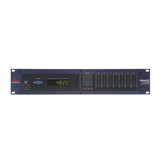
Page 15: Front Panel (4820)
232 protocol. This connection requires a Null Modem cable and one is included with the unit. 3. Alpha Numeric Display This display shows the ID# of the DriveRack 4820 unit. It can also show various error codes. 4. Input Meters The DriveRack 4820 provides four independent eight segment input headroom meters that range from SIG (-48dB) to 0dB. -
Page 16: System Architect Control Software
Gate, Limiter, Compressor or Auto Gain Control. 1. 4 - System Architect Control Software The System Architect software provides control and monitoring of the DriveRack 4800 and 4820 devices. Multiple units can be networked and controlled together along with other products from Harman Professional. - Page 17 • Once the software installation has been completed, it is recommended that you restart your computer. Note You must disable virus protection software during the installation of the System Architect software. ® Section 1 Getting Started DriveRack ® 4800/4820 User Manual...
- Page 18 ® DriveRack Section 1 Getting Started ® DriveRack ® 4800/4820 User Manual...
-
Page 19: Philosophy
Section 2 ® DriveRack DriveRack Philosophy PRESETS ATTRIBUTES ®... -
Page 20: Driverack 4800/4820 Philosophy
A Preset is the name given to the audio processing and routing that is occurring in the DriveRack 4800 or 4820. Up to 50 Presets can be stored in the DriveRack 4800 or 4820. The Preset can be further broken down into two parts: the signal path (or Configuration) and the actual Parameters (listed below) found in the individual processing functions or modules. -
Page 21: Section 3 - Front Panel Operation
Section 3 ® DriveRack Front Panel Operation NAVIGATION MODES ®... -
Page 22: Navigation
Input Graphic EQ on Input B, you would simply press the INPUT B button then the EQ1 button, and the Input Graphic EQ on input B would be highlighted. ® DriveRack ® 4800/4820 User Manual... -
Page 23: Modes Of Operation
STORE/DELETE button, where Store Preset is the standard mode that is found by pressing the button, and Delete Preset is the alternate mode that is accessed by pressing and holding for more than two seconds. ® DriveRack ® 4800/4820 User Manual... - Page 24 3. Navigate to the processing function that you want to copy by pressing the desired Channel and Function buttons. 4. Once at the function, press the PREV/COPY button to copy the parameters. DriveRack ® 4800/4820 User Manual ® DriveRack ®...
- Page 25 WARNING: At least one preset must remain stored at all times, or there will be no preset to start with when creating other presets. DO NOT DELETE ALL PRESETS! ® Front Panel Operation DriveRack ® 4800/4820 User Manual Section 3...
- Page 26 M M e e t t e e r r M M e e n n u u - The Meter menu provides you with additional high resolution meters for all the dynamics functions of the DriveRack 4800. 1. While in Edit mode press and hold the UTILITY/METER button. DriveRack ® 4800/4820 User Manual ® DriveRack ®...
- Page 27 2. Use the CHANNEL and FUNCTION buttons to navigate around the processing matrix. 3. In positions where a change of processing is possible, turning the Encoder #1 knob will accomplish this change. 4. To link adjacent like functions, turn Encoder #3 knob. ® DriveRack ® 4800/4820 User Manual...
- Page 28 5. Once the desired configuration is created, press and hold the RTA/LOAD button to load the configura- tion. 6. To exit Configuration and return to Edit mode without making any changes to the configuration, press the PRESET button. DriveRack ® 4800/4820 User Manual ® DriveRack ®...
- Page 29 Section 4 ® DriveRack Software Operation MODULE VIEW DEVICE VIEW VENUE VIEW ®...
-
Page 30: Section 4 - Software Operation
Software Operation 4.1 - DriveRack Philosophy The most basic storage elements of the DriveRack 4800 and 4820 are the Attribute and the Preset. Attributes are global parameters for that unit, while Presets are snapshots of the current processing func- tions or modules, their location in the signal path, and their parameters (see Section 2.1 for more informa- tion about Attributes and Presets). -
Page 31: Device Window
The DriveRack Device View (seen below) is accessed by double-clicking the device icons in System Architect’s Venue View, and provides access to the processing modules and other features of the DriveRack 4800 or 4820 devices. Like the processing icons, the device icons look like the devices they represent. ®... - Page 32 The Zone Controller Wizard is also important if you wish to use the DriveRack 4800 or 4820 with ZC wall panel controllers. The Utility Menu holds several of the attributes of the DriveRack 4800 including the Sample Rate, Analog I/O Gain Structure, Real Time Clock, the Preset Range, and LCD Intensity.
- Page 33 The Preset Tool lets you store and recall Presets on the DriveRack device when online. It is important to note that the Preset Tool is used to store Presets on the DriveRack Device while the File Menu/Save Preset is used to save a Preset File on the computer. ® DriveRack ® 4800/4820 User Manual...
- Page 34 Meters. Mutes provide a quick way of muting DriveRack 4800 outputs. The Solos employ the Mutes for soloing of a single channel during setup. Outside of the “normal” DriveRack 4800/4820 signal path, the RTA provides an additional utility that lets you analyze incoming signals. Clicking on the RTA icon opens the RTA viewer.
-
Page 35: Venue View
If Manage Roles is set up, the File Menu can log users out or switch users, providing varying amounts of control for these users. ® Software Operation DriveRack ® 4800/4820 User Manual Section 4 Section 4... - Page 36 Custom Control Panels offer total versatility in designing and controlling a venue. They enable you to man- age venues more easily by simplifying common editing tasks and restricting access to audio systems by other users. DriveRack ® 4800/4820 User Manual ® DriveRack ®...
- Page 37 The Zoom toolbar lets you zoom in or out in a venue. Venue Insert Menu The Insert Menu provides the ability to insert devices into a venue. ® Software Operation DriveRack ® 4800/4820 User Manual Section 4 Section 4 Section 4 Section 4 Section 4 Section 4...
- Page 38 A A c c c c e e s s s s C C o o n n t t r r o o l l allows the administrator to restrict or allow access to different parts of System Architect for multiple users. O O p p t t i i o o n n s s accesses settings related to the way System Architect functions and displays information. ® DriveRack ® 4800/4820 User Manual...
- Page 39 The Help Menu provides links to the Help File with different ways to find information; it also provides information about System Architect and the various .dll files that are compiled within it. ® Software Operation DriveRack ® 4800/4820 User Manual Section 4...
- Page 40 ® DriveRack Section 4 Software Operation ® DriveRack ® 4800/4820 User Manual...
-
Page 41: Section 5 - In Use
Section 5 ® DriveRack In Use FRONT PANEL OPERATION SOFTWARE OPERATION ®... -
Page 42: Front Panel Operation
To make a Configuration change: 1. Since the preset was just recalled, we’re already in Edit Preset mode and can press and hold the WIZARD/CONFIG button for two seconds to enter Configuration mode. DriveRack ® 4800/4820 User Manual ® DriveRack ®... - Page 43 5. Turn Encoder knob #3 to link the Compressors on Inputs 1 and 2. 6. Select the Input Router on Input A by pressing the MIX/ROUTE button and INPUT A button. ® Section 5 In Use DriveRack ® 4800/4820 User Manual...
- Page 44 3. Press NEXT to access the next page of parameters. Continue until all desired pages of parameters have been edited. DriveRack ® 4800/4820 User Manual ® DriveRack ®...
- Page 45 9. Make the changes by finding the Input channels A and B and adjusting their relative amounts using the Encoders. 10. Press the PRESET/RECALL button to return to the main preset screen. ® Section 5 In Use DriveRack ® 4800/4820 User Manual...
-
Page 46: Gui Operation
The example begins with recalling a preset from the Preset Table: 1. Open the Device Window by double clicking on the DriveRack 4800 or 4820 icon in System architect. 2. Click the RECALL button on the Preset Tool. The Preset Recall dialog appears, where you can select a preset and View it, Recall it, or Cancel the Recall operation. - Page 47 1. Click on the Store button on the Preset Tool. The Store dialog opens. 2. Select the location in the Preset Table where you want to store the preset. 3. Select the preset’s name. 4. Click the Store button to store the preset. ® Section 5 In Use DriveRack ® 4800/4820 User Manual...
- Page 48 ® DriveRack Section 5 In Use ® DriveRack ® 4800/4820 User Manual...
- Page 49 Section 6 ® DriveRack Detailed Parameters DETAILED PARAMETERS ®...
-
Page 50: Section 6 - Detailed Parameters
Section 6 Detailed Parameters The DriveRack 4800 and 4820 provide a wealth of processing capabilities. This processing can be broken into two distinct sections: Input Processing and Output Processing. Both the Input and Output sections offer two types of processing functions, Fixed and Insert. Fixed processing modules can be linked and/or switched with a similar type of function, but they are fixed in their location in the DSP path. -
Page 51: Input Router
Provides Gain control of the internal Pink Noise source (-20 to +20 dB). Pink Noise On/Off switch Turns the pink noise on or off Master Gain fader Provides Gain control for the Router module (–inf to +20dB). ® ® Detailed Parameters DriveRack ® 4800/4820 User Manual Section 6... -
Page 52: Input Graphic Eq
Section 6 Detailed Parameters 6.3 - Input Graphic EQ The DriveRack 4800/4820 provides a 31 band Graphic EQ on each input channel. This EQ offers up to +/-15dB of gain at each of the 31 ISO frequency centers. EQ On/Off switch This turns the Graphic EQ on and off. -
Page 53: Input 9-Band Parametric Eq
6.4 - Input 9-Band Parametric EQ The DriveRack 4800 and 4820 offer a second EQ (EQ2), after the input Graphic EQ, that can be config- ured as either a Graphic or 9-Band Parametric EQ. The 9-Band Parametric EQ provides Frequency, Gain and Q control for each EQ band. -
Page 54: Input Delay
Section 6 Detailed Parameters 6.5 - Input Delay Each input channel of the DriveRack 4800 and 4820 provide up to 680 mSec of Input Delay. Delay On/Off switch This turns the input channel Delay module on and off. Delay fader This sets the amount of delay time and is adjustable in either 10 or 20 µSec steps (one sample at either 96... -
Page 55: Output Mixer
Provides gain control for each of the input channels (–inf to +20dB). Master Gain fader Provides Gain control for the Mixer module (–inf to +20dB). Master Mute switch Allows output muting of the Mixer module. ® DriveRack ® 4800/4820 User Manual... -
Page 56: Output Router
Selected Source Switch Allows selection between the input channels (Channels A-D). Master Gain fader Provides Gain control for the Router module (–inf to +20dB). Master Mute switch Provides Mute control for the Router module. ® DriveRack ® 4800/4820 User Manual... -
Page 57: Output Bandpass Filter/Crossover
DriveRack 6.8 - Output Bandpass Filter/Crossover The DriveRack 4800/4820 provides a Bandpass Filter on each output channel. These filters can be con- figured as Crossovers so you can adjust the frequency content of the adjacent output channels. Band Select switch This selects the specific band or channel to be adjusted. -
Page 58: Output 6-Band Parametric Eq
Detailed Parameters 6.9 - Output 6-Band Parametric EQ The DriveRack 4800 and 4820 offer an Output 6-Band Parametric EQ on each output channel. The 6- Band Parametric EQ provides Frequency, Gain and Q control for each of the 6 EQ bands. -
Page 59: Output Delay
Section 6 Detailed Parameters 6.10 - Output Delay The output channels of the DriveRack 4800 and 4820 provide up to 1360 mSec of configurable Delay, this means that the Delay can be allocated to where it is needed. Delay On/Off switch This turns the output channel Delay module on and off. -
Page 60: Advanced Feedback Suppression (Afs ) Insert
® ) Insert The DriveRack 4800/4820 offers the exclusive dbx Advanced Feedback Suppression (AFS) feedback elim- ination module as an Insert processing function on the Input channels. This feedback suppression algo- rithm reduces feedback by first finding the location of a feedback frequency and then placing a very sharp notch filter at the exact frequency that is feeding back. - Page 61 Fixed Filters equals the number of Live Filters. The number of Fixed fil- ters can range between 0 and 12. Total Filters fader This parameter selects the total number of filters available and can range between 0 and 12. ® DriveRack ® 4800/4820 User Manual...
-
Page 62: Automatic Gain Control (Agc) Insert
6.12 - Automatic Gain Control (AGC) Insert The Automatic Gain Control Insert is available in the DriveRack 4800 and 4820 in both the Input and Output Insert modules. Automatic Gain Control (or AGC) is used to keep the average level of a signal con- stant. - Page 63 The Limiter Release parameter sets the rate at which the Limiter will go out of gain reduction once the sig- nal drops below the threshold. The Release range is between 360 and 5 dB/Sec. Auto mode deactivates this parameter. ® DriveRack ® 4800/4820 User Manual...
-
Page 64: Autowarmth Insert
® Insert The Fletcher-Munson Equal-Loudness curves show that the perception of low frequency signals decreases quickly with decreasing volume. The DriveRack 4800 and 4820 offer the AutoWarmth Insert module on ® each output (Insert 1) to compensate for this perceived loss in low frequencies. AutoWarmth is a patent pending process that compensates for the naturally occurring perceived loss of low frequency at low signal levels. -
Page 65: Compressor Insert
Detailed Parameters 6.14 - Compressor Insert The DriveRack 4800 and 4820 offer an Insert Compression function on both the Input and Output Inserts. This function is modeled from classic dbx Compressors such as the 160 and the 165. Compressor On/Off switch This switch turns the Compressor module on and off. - Page 66 Auto mode. Hold fader The Hold parameter is the time the 4800/4820 remains in compression after the signal has dropped back below the threshold. Hold is adjustable between 0 to 500 mSec and is dynamically set while in Auto mode.
-
Page 67: De-Esser Insert
Detailed Parameters 6.15 - De-Esser Insert The DriveRack 4800/4820 offers a De-Esser module available on the Input Inserts. This De-Esser effect is ideal for removing unwanted vocal sibilance and is based on the original dbx 902 De-Esser module. A De- Esser works by inserting a high frequency boost EQ filter in the detector path of a Compressor to “bias”... -
Page 68: Noise Gate
6.16 - Noise Gate The DriveRack 4800 and 4820 provide a Noise Gate Insert that can be placed in both the Input and/or the Output section. A Noise Gate is used to remove unwanted low-level noise in a system. The basic premise behind a Noise Gate is that gain reduction or Gating will be applied to the channel unless there is a signal that is above some Threshold. -
Page 69: Limiter Insert
Detailed Parameters 6.17 - Limiter Insert The DriveRack 4800/4820 units offer a Limiter in the Output Insert position. A Limiter operates on the same principles as a compressor (see section 6.14) but it is designed and used more for system protection rather than musical dynamics control. - Page 70 Auto mode. Hold fader The Hold parameter is the time the 4800/4820 continues to reduce gain after the signal has dropped back below the threshold. Hold is adjustable between 0 and 500 mSec and is dynamically set while in Auto mode.
-
Page 71: Notch Filter Insert
6.18 - Notch Filter Insert The 4800 and 4820 units offer 6-Band Notch Filter that can be inserted in the Input section. The Notch filter is designed to provide a significant amount of cut in very narrow frequency bandwidths to remove room resonances and other unwanted artifacts. -
Page 72: Subharmonic Synthesizer Insert
This controls the amount of bass synthesized within the 24 to 36 Hertz frequency band. This parameter is adjustable between 0 and 100%. 36-56Hz Level fader This controls the amount of bass synthesized within the 36 to 56 Hertz frequency band. This parameter is adjustable between 0 and 100%. ® DriveRack ® 4800/4820 User Manual... -
Page 73: Section 7 - Utilities
Section 7 ® DriveRack Utilities UTILITIES ®... -
Page 74: Miscellaneous
Section 7 Utilities As stated earlier, the Utility menus contain many of the attributes of the DriveRack 4800 and 4820 devices. With the exception of Access Rights (which are stored manually), these attributes are stored instantly as they are changed. They are broken down into sub menus in both the GUI and on the unit. While these sub menus are different in their arrangement, all the same attributes are available. -
Page 75: Real Time Clock
7.4 - Real Time Clock The DriveRack 4800 and 4820 have an internal Real Time Clock. This clock allows the devices to load a preset based on a time schedule, for automated system changes. The real time clock is set by syncing the DriveRack device to a computer from which it extracts the clock information. - Page 76 Note: Setting up a basic Network The DriveRack 4800 and 4820 come with an included Ethernet cable. The DriveRack 4800/4820 is set up at the factory for DHCP allowing it to be assigned an IP address by a DHCP Server. If there is no DHCP Server present, the DriveRack will then default to Auto-IP, meaning that it will give itself a semi-random IP address.
-
Page 77: Appendix
Appendix ® DriveRack ®... -
Page 78: Specifications
Interchannel Crosstalk: Processing Pre EQ Type: Range: DriveRack ® 4800/4820 User Manual Female XLR Electronically balanced, RF filtered >50k ohms Software selectable for: +28, +26, +24, +22, +20, +18, +16, +14 dBu >40 dB typical, >55 dB at 1 kHz... - Page 79 3.5” x 19” x 12.15” Weight: 11 lbs. (14 lbs. w/audio transformers) Shipping Weight: 12.5 lbs. (15.5 lbs. w/audio transformers) ® ® , Compressor, Auto Gain Control, Peak Limiter, Sub-Harmonic Synth, JT-11 and JT-123-dbx ® DriveRack Appendix ® 4800/4820 User Manual...
-
Page 80: Block Diagram
® DriveRack Appendix A.2 - Block Diagram ® DriveRack ® 4800/4820 User Manual... -
Page 81: Preset Table
. s r g i s a t i . r e c i l i t a y . s h t i f i f h t i ® 4800/4820 User Manual e t l... -
Page 82: Digital I/O And Clocking
Appendix A.5 - Digital I/O and Clocking A.6 - Word Clock Termination 75Ω Coaxial Cable BNC “T” 75Ω BNC Terminator DriveRack ® 4800/4820 User Manual Clock Source 4800/4820 4800/4820 4800/4820 ® DriveRack ®... -
Page 83: Zone Controller Wiring And Installation
The ZC-fire interface unit monitors the state of the relay (n.o. or n.c.) and upon the state of change, notifies the 4800/4820, which then mutes its outputs. - Page 84 ® DriveRack Appendix Diagram A Diagram B ID# 1 ID# 4 80-1342-A 80-1342-A Diagram C ® DriveRack ® 4800/4820 User Manual...
- Page 85 Cable Specification: EIA/TIA 568A Standard (pin to pin) 24 AWG wire RJ-45 (8-Position) Diagram A Diagram C ® RJ-45 (8-Position) White/Green -VREF Green -Zone 1 White/Orange -Zone 2 Blue -Zone 3 White/Blue -Zone 4 Orange -Zone 5 White/Brown -Zone 6 Brown -GND Diagram B DriveRack Appendix ® 4800/4820 User Manual...
-
Page 86: Wiring Diagram
® DriveRack Appendix A.8 - ZC-4 Wiring Diagram ® DriveRack ® 4800/4820 User Manual... -
Page 87: Factory Reset
DriveRack A.9 - Factory Reset Factory Reset Information In the event that a reset is required, the DriveRack 4800/4820 offers you the option of performing a “Hard” or “Soft” Factory Reset. Power-Up Button Functions All Power-Up Functions will use the MUTE 1 through MUTE 8 buttons. All Power-Up Functions require a button(s) to be pressed and held as the unit power is turned on. -
Page 88: Ethernet Networking
This section of the appendix provides a step-by-step guide on how to properly connect the DriveRack 4800 or 4820 to a Local Area Network (LAN) for several different network architectures. The first topology is a simple direct connection using the provided Ethernet cable. The second method describes how to connect several DriveRack units to create an isolated network using an Ethernet switch with DHCP and configure them with the System Architect GUI. -
Page 89: Connecting The Computer Directly To The Driverack
169.254.x.y or 0.0.0.0.) Otherwise skip to step 9. a. From the PC Control Panel open the Network Connections window. b. Right click on the Local Area Network (LAN) connection that is wired to the 4800/4820 and select ‘Properties’. -
Page 90: Setup Of A Simple Isolated Ethernet
The proxy feature allows you to access a 4800/4820 over a complex or remote network. An example of this is when the PC and the 4800/4820 reside on different subnets. The mechanism that is used by default for the System Architect software to discover and maintain a connection to the 4800/4820 DriveRack ®... -
Page 91: Virtual Private Networks (Vpn)
• The Network Wizard will not allow address changes on any 4800/4820 that is connected to the GUI via a proxy. • When connecting to a 4800/4820 through a proxy, the locate tool will only work on the unit that is setup as the proxy, and not the devices that are connected through it. -
Page 92: Network Troubleshooting
Check the following connections: • 4800/4820 device – If there is a valid connection on the 4800/4820 you will see a solid green LED. • PC running the System Architect software •... -
Page 93: Copyrights
Copyright (c) 1993 The Regents of the University of California. All rights reserved. This software was developed by the Computer Systems Engineering group at Lawrence Berkeley Laboratory under DARPA contract BG 91-66 and contributed to Berkeley. ® Appendix DriveRack ® 4800/4820 User Manual... - Page 94 WHATSOEVER RESULTING FROM LOSS OF USE, DATA OR PROFITS, WHETHER IN AN ACTION OF CONTRACT, NEGLIGENCE OR OTHER TORTIOUS ACTION, ARISING OUT OF OR IN CONNECTION WITH THE USE OR PERFORMANCE OF THIS SOURCE CODE. DriveRack ® 4800/4820 User Manual ® DriveRack ®...
- Page 95 ® DriveRack Appendix ® DriveRack ® 4800/4820 User Manual...
- Page 96 ® 8760 South Sandy Parkway • Sandy, Utah 84070 Phone: (801) 568-7660 • Fax (801) 568-7662 Int’l Fax: (801) 568-7583 Questions or comments? E-mail us at: customer@dbxpro.com or visit our World Wide Web home page at: www.dbxpro.com A Harman International Company 18-0353-A...
Need help?
Do you have a question about the DriveRack 4820 and is the answer not in the manual?
Questions and answers