Table of Contents
Advertisement
Quick Links
Advertisement
Chapters
Table of Contents

Related Manuals for Domino M230i-T100

Summary of Contents for Domino M230i-T100
- Page 1 Domino Product Manual Essential User Information M230i-T100 M230i-T150...
- Page 2 THIS PAGE INTENTIONALLY LEFT BLANK EPT021262 Issue 1 February 2016...
- Page 3 DOMINO M230I T100/T150 LABELLER This manual, Domino Art No. EPT021262 has been produced for use in the installation and operation of the Domino M230i-T100/T150 Labeller, and to reinforce and complement any training program available with the product. It is not designed to replace any such training program.
- Page 4 CONTENTS OF EC DECLARATION OF CONFORMITY (in accordance with BS EN ISO/IEC 17050-1:2010 No. Doc-0009978 Issuer's name: Mectec Elektronik AB Issuer's Address: Mectec Elektronik AB, Agnesfridsvägen 189, SE- 213 75 Malmö, Sweden. Object of the declaration: T100-160-110x66-Left T100-260-110x110-Right T150-160-150x110-Left T100-160-110x66-Right T100-260-110x150-Left T150-260-150x110-Left T100-160-110x110-Left...
-
Page 5: Ec Declaration Of Conformity
Risk assessment and risk reduction 2006/42/EC : Machinery Directive 2004/108/EC : EMC Directive 2011/65/EU : RoHS Directive Signed for and on behalf of Domino Printing Sciences Agnesfridsvägen 189 SE- 213 75 Malmö, Sweden Date: 2016-02-04 Rikard Malmback Managing Director (Mectec Elektronik AB) - Page 6 THIS PAGE INTENTIONALLY LEFT BLANK EPT021262 Issue 1 February 2016...
-
Page 7: Table Of Contents
INTRODUCTION PART 1: Introduction CONTENTS Page INTRODUCTION ................... 1-3 Identification and CE mark ............... Machine Identification – Serial Number Label ......DOCUMENT INFORMATION ..............LABELLERS – EQUIPMENT INFORMATION ........Machine modules ................Printer ....................1-5 Printer design ................Main parts of the Printer .............. Print head down ................ - Page 8 INTRODUCTION THIS PAGE INTENTIONALLY LEFT BLANK EPT021262 Issue 1 February 2016...
-
Page 9: Introduction
Rated power [kW]: 0.80 Rated power [kW]: 0.80 90-250VAC / 50-60 Hz / 6,3 A 90-250VAC / 50-60 Hz / 6,3 A PN = Part number Domino Printing Science plc Mectec Electronik AB Agnesfridsvägen 189 Agnesfridsvägen 189 SE-213 75 Malmö SE-213 75 Malmö... -
Page 10: Document Information
• pass the manual on to any subsequent holder or user of the equipment A Technical manual is available on a CD. This document holds maintenance instructions intended for use by specialised personnel mandated by the Domino or authorised representatives. EPT021262 Issue 1 February 2016... -
Page 11: Labellers - Equipment Information
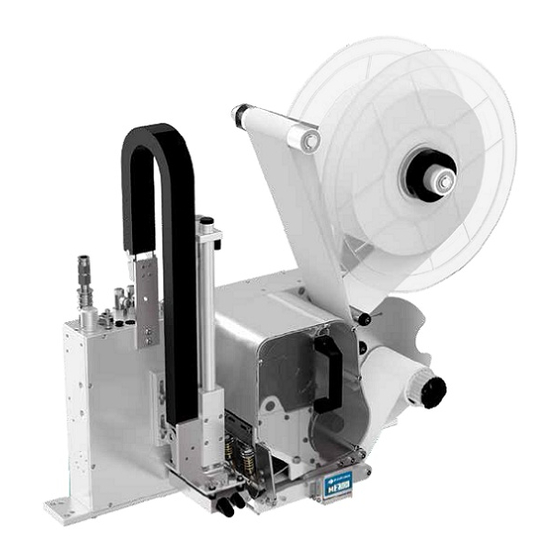
INTRODUCTION LABELLERS – EQUIPMENT INFORMATION This M230i-T100 and M230i-T150 Labellers are designed for printing and applying labels. There are different variants of the M230i-T100 and M230i-T150 Labellers. A labeller consists of three modules. (1) Applicator (2) Printer (3) Printer Control... -
Page 12: Printer Design
INTRODUCTION Printer design The printers are designed so the label and ribbon rollers together with the print head are accessible from the Operator side. The opposite side, the Service side holds the driving belts, cables and an electronic circuit board and are concealed under a cover plate. -
Page 13: Main Parts Of The Printer
INTRODUCTION Main parts of the Printer (1) Label un-winder (2) Backing paper re-winder (3) Printer cable (4) Ribbon take-up (5) Ribbon supply (6) Print head lifting handle (7) Print head Note: Small differences can be found on the printer model, but the general construction is the same. -
Page 14: Print Head Down
INTRODUCTION Print head down (1) Stepper motor (2) Print head lifting handle (3) Print head pressure device (4) Print head (5) Ribbon guide Print head up (6) Ribbon take up roller (7) Dispensing beak (8) Platen roller Printer underside (without peel roller) (9) Label-gap sensor EPT021262 Issue 1 February 2016... -
Page 15: Peel Roller
INTRODUCTION Peel roller The peel roller (highlighted in gray below) is mounted under the platen roller and ensures sufficient contact between backing paper and platen roller for accurate label feed. The peel roller is necessary for large label rolls, it extends the safety margins and reduces the maintenance time. -
Page 16: Pcu
INTRODUCTION The Printer Control Unit (PCU) controls the operation of the printer. The PCU unit is also equipped with an ACC (Application Control Card) that controls the applicator. The ACC is capable of controlling applicators having numerous cylinders and is mounted within the PCU. Applicator The Applicator is mounted in front of the printer/labeller and can depending on the design, apply labels either on stationary or moving objects.The... -
Page 17: Options
• Label check sensor • Touch panel interface • Floor stand • Pneumatic Corner Wrap Brush • Machine stop/Emergency stop Please contact supplier Domino for a current list of M230i-T100 and M230i- T150 series accessories. EPT021262 Issue 1 February 2016 1-11... - Page 18 INTRODUCTION THIS PAGE INTENTIONALLY LEFT BLANK 1-12 EPT021262 Issue 1 February 2016...
- Page 19 SAFETY PRECAUTION PART 2: Safety Precaution CONTENTS Page SAFETY PRECAUTION ................. 2-3 Information - Warning, Caution & Notes .......... 2-3 Warning signs .................. PERSONNEL ..................2-4 Electricians ..................GENERAL SAFETY PRECAUTIONS ............. 2-5 Maintenance work on the Applicator ..........Remote control ................2-6 Compressed Air ................
- Page 20 SAFETY PRECAUTION THIS PAGE INTENTIONALLY LEFT BLANK EPT021262 Issue 1 February 2016...
-
Page 21: Safety Precaution
SAFETY PRECAUTION SAFETY PRECAUTION To ensure maximum safety, always read this section carefully before doing any work on the equipment or making any adjustments. Information - Warning, Caution & Notes WARNINGS, CAUTIONS and Notes used throughout this manual are highlighted by use of international hazard symbols. The following definitions of all three special notices are shown below in the way that they are presented in the manual. -
Page 22: Personnel
SAFETY PRECAUTION PERSONNEL Only skilled or instructed personnel are allowed to work on the equipment. The manufacturer declines all responsibility for injury or damage if the instructions in this manual are not followed. Personnel are responsible for: • The equipment and the work area around the equipment •... -
Page 23: General Safety Precautions
SAFETY PRECAUTION GENERAL SAFETY PRECAUTIONS Maintenance work on the Applicator Before any maintenance work is done inside the machine, always remember to: (1) Stop the Applicator, see section: 3.2 Stopping the Applicator. (2) Switch off the Applicator’s main switch. (3) Use the hand slide valve at the top of the Applicator module to turn the air ON/OFF. -
Page 24: Remote Control
SAFETY PRECAUTION Remote control WARNING: The Applicator can be remotely started, stopped and accessed from a supervision unit or the production line’s control system. To disable remote start of the Applicator, disconnect the Applicator according to instructions (1)-(3). Compressed Air WARNINGS: Contaminated compressed air may cause unpredictable behaviour of machine valves. -
Page 25: Machine Safety Devices
SAFETY PRECAUTION MACHINE SAFETY DEVICES Machine Stop or Emergency stop The Tamp applicator is designed for a Machine Stop. The stop can work as a Machine stop that only stops the tamp applicator. The air is switched off immediately and the system is de-pressurized when activating the machine stop. -
Page 26: Risk Area
SAFETY PRECAUTION Risk area The risk area is the volume under the unit where the applicator is mounted (depending on the direction of the Tamp applicator installation). The main risk is pinching or crushing fingers when the Tamp applicator returns to its home position. Ensure hands and fingers are kept away from the machine when it is operating. -
Page 27: Noise Levels
SAFETY PRECAUTION NOISE LEVELS Domino have no control over specific site conditions, duration of use, state of maintenance or adjustment of the machine. The following Noise level data are measured on the smallest and the largest of the T100-T150 Labellers. -
Page 28: Manual Lifting
SAFETY PRECAUTION MANUAL LIFTING It is recommended that two persons lift the Applicator by the mounting rail to avoid damages to the equipment. 2-10 EPT021262 Issue 1 February 2016... -
Page 29: Part 3: Technical Data
TECHNICAL DATA PART 3: TECHNICAL DATA CONTENTS Page TECHNICAL DATA ................Measurements - T100-160-110x66-R ..........Measurements - T150-360-150x210-R ........... EPT021262 Issue 1 February 2016... - Page 30 TECHNICAL DATA THIS PAGE INTENTIONALLY LEFT BLANK EPT021262 Issue 1 February 2016...
- Page 31 TECHNICAL DATA TECHNICAL DATA The technical data for M230i-T100 and M230i-T150 tamp applicator are represented by smallest and largest models. There are minor deviations in the data of the models in between, but they are not presented here, except pads and labels sizes.
- Page 32 TECHNICAL DATA Measurements - M230i-T150-360-150x210-R (mm) Note: Heights, lengths and widths may differ depending on configuration. EPT021262 Issue 1 February 2016...
- Page 33 TECHNICAL DATA Tamp applicator M230i-T100 M230i-T150 Dimensions See drawings Total weight 32.1 kg 37.3 kg Applicator weight 6.4 kg 9.3 kg Printer weight 17.7 kg 20 kg Mounting kit Power supply 90-250VAC Mains input Power consumption (230 VAC/50 Hz) Maximum operating 1.3A/299W...
- Page 34 TECHNICAL DATA Tamp applicator M230i-T100 M230i-T150 Print head width 108mm 162mm Resolution 12 dots/mm Web width max width of 108mm 169mm backing paper Label roll - Max diameter 340mm See also Part 6: Label & Ribbon Selection. Label roll - Inner diameter 75.5 - 77.3mm...
- Page 35 TECHNICAL DATA Tamp applicator M230i-T100 M230i-T150 Recommended printer 200mm/s 125mm/s speed Recommended highest 1.3 seconds 3.5 seconds cycle speed. 45 labels/min 17 labels/min Max recommended linear 30m/min speed of conveyor PCU dimensions 405 x 280 x 130mm Including cable glands and mounting plate.
- Page 36 TECHNICAL DATA Tamp applicator M230i-T100 M230i-T150 CPU for Printer, on 2 x 32 MHz motherboard Memory 8 MB True Type fonts and graphic, flash 2 MB Label text, battery backed up RAM 2 x 1 MB Print area/label bitmap 2 x 128 kB...
- Page 37 TECHNICAL DATA Tamp applicator M230i-T100 M230i-T150 Inputs PNP (fixed) PNP/NPN switchable (Scanner Good Read) Input range Nominal voltage 24VDC Operating range 9-36VDC Nominal input current Variations depending of the input voltage 1-3mA (Inputs are referring to ACC/controller 0VDC) Outputs (CPU)
- Page 38 TECHNICAL DATA THIS PAGE INTENTIONALLY LEFT BLANK 3-10 EPT021262 Issue 1 February 2016...
- Page 39 INSTALLATION PART 4: INSTALLATION CONTENTS Page SITE REQUIREMENTS ..............4-3 PRE-INSTALLATION ..............4-3 INSTALLATION ................4-4 MOUNTING THE MACHINE ............4-4 COMPRESSED AIR CONNECTION ..........4-5 ELECTRICAL AND COMMUNICATION CONNECTIONS ... 4-6 Printer cable ................4-7 Applicator cable ..............4-7 Beacon cable (optional) ............
-
Page 40: Installation
INSTALLATION THIS PAGE INTENTIONALLY LEFT BLANK EPT021262 Issue 1 February 2016... -
Page 41: Site Requirements
INSTALLATION SITE REQUIREMENTS The tamp applicator should be mounted securely in the desired location. It should not be placed close to any heat source or in direct sunlight. It should not be located in any hazardous environment, or in close proximity to any flammable solvents or gases. -
Page 42: Installation
It is recommended that two persons lift the Tamp applicator by the mounting rail to avoid damages to the equipment. Please contact Domino if you have any questions on how to install the units. (1) Remove the packaging material from the Tamp applicator. -
Page 43: Compressed Air Connection
INSTALLATION COMPRESSED AIR CONNECTION The Tamp applicator requires compressed air supplied with a pressure of 6 bar. CAUTION: The internal working pressure of the cylinders has been reduced for safety reasons. It is highly recommended to avoid using a higher pressure than necessary. The Tamp applicator have air regulators fitted as standard. -
Page 44: Electrical And Communication Connections
INSTALLATION ELECTRICAL AND COMMUNICATION CONNECTIONS The electrical feed can be from 110-240 V. External devices, such as PLCs, Sensors and Scanners, etc are connected using the terminal blocks, see illustrations. The terminal blocks contain +24V and 0V to supply external product detectors, sensors, etc. 9 10 11 12 (1) Power On/Off switch (7) CH1 - RS232... -
Page 45: Printer Cable
INSTALLATION Printer cable The printer cable is pre-connected to the printer in one end; the other end must be connected to the PCU. Mount the printer cable through the printer cable inlet in the rear of the PCU. Connect the printer cable to the PCU. Secure the mounting plate to the unit. -
Page 46: Beacon Cable (Optional)
INSTALLATION Beacon cable (optional) The beacon cable is installed to the beacon tower light (option). Mount the beacon cable through the beacon cable inlet. Connect the beacon cable to the ACC in the PCU. Secure the mounting plate to the unit. (3) Applicator cable connector - CN10 (4) Beacon cable connector - CN9 EPT021262 Issue 1 February 2016... -
Page 47: Acc Terminal Blocks For External Connections
INSTALLATION ACC terminal blocks for external connections External devices such as PLCs, sensors and scanners, etc, are connected using the EXTERNAL terminal blocks. CAUTION: Do not connect to the INTERNAL terminal blocks. 5. 24V & 0V are available to supply external equipment, like sensors. 6. -
Page 48: Supply Voltage - Terminal Blocks Cn5 & Cn6
INSTALLATION Supply voltage - Terminal blocks CN5 & CN6 The terminal blocks CN5 and CN6 contain +24V and 0V to supply external product detectors, sensors etc. External inputs - Terminal blocks CN3 The CN3 terminal block provides input connections for product detectors, sensors etc. -
Page 49: Connect A Relay Or Optocoupler To Acc Inputs
INSTALLATION Connect a relay or optocoupler to ACC inputs CAUTION: Do not connect the internal voltage to an external source. It is strictly prohibited to connect the internal ACC 0V DC to an external 0V DC (e, g. the 0V DC in a PLC). EPT021262 Issue 1 February 2016 4-11... -
Page 50: External Output - Terminal Block Cn4
INSTALLATION External output - Terminal block CN4 The default settings for output RE1-RE7 are configured as below, but can be amended in the setup program. Output Function Comments Reference Voltage 1 See further down for more information Printer ready Data ready Applicator in home position Cycle completed... -
Page 51: Connect An External Load To The Relay Outputs (Example)
INSTALLATION Connect an external load to the relay outputs (example) JP2 - Reference voltage jumper REF1 = Jumper in right position The same reference voltage (connected to pin 29 or pin 40) is used in all relays. REF2 = Jumper in left position The reference voltage connected to pin 29 is used in relays RE1-RE5. -
Page 52: Optional Wlan Communication
INSTALLATION OPTIONAL WLAN COMMUNICATION The Tamp applicator is equipped with a standard Ethernet (LAN) connection. However it is possible to exchange this to an optional WLAN/ LAN interface and replace the default LAN interface. (including an Ethernet cable connection) Please see the part “Printer/Labeller & PCU/LCU” in the Technical manual for instructions how to configure WLAN/LAN interface. - Page 53 OPERATING PROCEDURES PART 5: OPERATING PROCEDURES CONTENTS Page POWER ON/OFF ................. 5-3 PCU ..................5-3 COMPRESSED AIR ON/OFF ............5-3 PRINTER - START / STOP / RE-START ........5-4 Start print ................5-4 Stop the printer ............... 5-4 Re-start the printer ..............5-4 APPLICATOR - START / STOP / RE-START .......
-
Page 54: Operating Procedures
OPERATING PROCEDURES THIS PAGE INTENTIONALLY LEFT BLANK EPT021262 Issue 1 February 2016... -
Page 55: Power On/Off
OPERATING PROCEDURES POWER ON/OFF Located at the rear of the PCU, use the Power switch to turn the power ON/ OFF. COMPRESSED AIR ON/OFF WARNING: Release the compressed air gradually in order to avoid rapid cylinder movement. Use the valve at the top of the applicator module to turn the air ON/OFF. The ON/OFF valve is a ventilating valve, which will de-pressurize the air system when compressed air is switched OFF. -
Page 56: Printer - Start / Stop / Re-Start
OPERATING PROCEDURES PRINTER - START / STOP / RE-START The start signals can be made in different ways depending on how the setup is made. The setup can be changed from the front panel at the PCU, or in the setup program at any time. -
Page 57: Applicator - Start / Stop / Re-Start
OPERATING PROCEDURES APPLICATOR - START / STOP / RE-START Start apply A label must be printed or fed before the applicator can start. The start signal to the applicator can be made by: • Product detector, or other start signal, to the apply input on the ACC board. -
Page 58: Machine Stop / Emergency Stop (Option)
OPERATING PROCEDURES MACHINE STOP / EMERGENCY STOP (OPTION) As an option the machine can be equipped with a Machine stop or Emergency stop which is an external stop function. The Machine stop only stops the labelling equipment. The Emergency stop stops the labelling equipment and a section of the production line. -
Page 59: Reset Machine Stop / Emergency Stop (Option)
OPERATING PROCEDURES Reset Machine stop / Emergency stop (option) To reset and restart the machine: (1) Press the RESET button on the Machine stop / Emergency stop. The cylinders will slowly return to their home positions. (2) The machine is now ready for operation. STOP FOR SERVICE Switch off the PCU and compressed air. -
Page 60: Pcu Controls
OPERATING PROCEDURES PCU CONTROLS Enter Set-Up mode. Confirm values when changed. Exit a menu without saving (when used instead of Enter). Go backwards one step in the menu system for each press. Go to Previous/Next menu or item. The buttons also change the displayed value. Confirm change with Enter key. - Page 61 OPERATING PROCEDURES RESET: This LED indicates that RESET has been set, and that the system has been reset to start the process. ERROR: This LED indicates an error in the process (for example): No labels, No ribbon, Print head up, Print head overheated.
-
Page 62: Label Selection From The Front Panel
OPERATING PROCEDURES Label selection from the Front panel Label selection from the front panel is not password protected and a label stored in the printer memory can easily be selected by using the keys on the front panel. Follow the steps below: Step Action Display Shows... -
Page 63: Change Labels
OPERATING PROCEDURES CHANGE LABELS Load labels (1) Open the Print head with the lifting handle. (2) Remove hood. (3) Open the Peel roller. (4) Install a new roll of labels as shown in the threading diagrams, and insert the band of labels under the Print head (Inside rolled or outside rolled labels). -
Page 64: Label Positioning
OPERATING PROCEDURES Label positioning CAUTION: Label positioning must always be performed after changing labels or ribbons. The label positioning procedure measures the label and stops it in a pre-set position on the dispensing beak. The stop position is set by the head distance and the feed length. Both the head distance and the feed length can be adjusted in the Setup program or via the PCU front panel. -
Page 65: Remove The Empty Label Roll
OPERATING PROCEDURES Remove the empty label roll (1) Open the print head/pressure roller with the print head lifting handle (2) Open the peel roller. (3) Remove the empty label roll. (4) Open the locking mechanism with the lever. (5) Pull out the backing paper. (6) Carefully clean the print head/ pressure roller. - Page 66 OPERATING PROCEDURES (10) To position the label correctly, the machine should feed and measure two to four labels. Ribbon Take-Up Roll for used ribbon Ribbon Supply- Install the new ribbon roll here Label positioning can be executed in two ways depending on the setup. •...
-
Page 67: Threading Diagrams
OPERATING PROCEDURES THREADING DIAGRAMS Labels on rolls Labels and Ribbon T50i Right hand printer Left hand printer Labels and Ribbon T60i Right hand printer Left hand printer Outside rolled labels Inside rolled labels Clarification EPT021262 Issue 1 February 2016 5-15... - Page 68 OPERATING PROCEDURES THIS PAGE INTENTIONALLY LEFT BLANK 5-16 EPT021262 Issue 1 February 2016...
- Page 69 LABEL & RIBBON SELECTION PART 6: LABEL & RIBBON SELECTION CONTENTS Page SELECTION OF MEDIA/LABELS ..........6-3 Print Labels ................6-3 LABEL SELECTION OVERVIEW ..........6-3 Label size ................6-3 SELECTION OF RIBBON ............6-4 Type of ribbon ................. 6-4 Back coating ................
- Page 70 LABEL & RIBBON SELECTION THIS PAGE INTENTIONALLY LEFT BLANK EPT021262 Issue 1 February 2016...
-
Page 71: Selection Of Media/Labels
SELECTION OF MEDIA/LABELS Domino recommends using approved media. Avoid thin or thick labels as they can be difficult to feed onto the applicator pad. Domino recommends that the gram weight of label stock should not be less than 55g/m or higher... -
Page 72: Selection Of Ribbon
LABEL & RIBBON SELECTION SELECTION OF RIBBON Type of ribbon The type of ribbon to be selected is dependent on the label material to be used, as it is possible to obtain a ribbon to suit virtually any type of label material. -
Page 73: Ribbon Width
LABEL & RIBBON SELECTION Ribbon width The required width of the ribbon depends on the width of the label used and the text printed on the label. If the whole width (or almost the whole width) of the label is printed then use a ribbon as wide as the label, plus 2mm on each side. - Page 74 LABEL & RIBBON SELECTION THIS PAGE INTENTIONALLY LEFT BLANK EPT021262 Issue 1 February 2016...
- Page 75 BASIC MAINTENANCE & TROUBLESHOOTING PART 7: BASIC MAINTENANCE & TROUBLESHOOTING CONTENTS Page CLEANING AND MAINTENANCE SCHEDULE ....... 7-3 GENERAL CLEANING ............7-4 Clean the Label-gap sensor ..........7-4 Clean the Platen roller ............7-5 Clean the Ribbon take-up roller .......... 7-5 Clean the Applicator ............
- Page 76 BASIC MAINTENANCE & TROUBLESHOOTING THIS PAGE INTENTIONALLY LEFT BLANK EPT021262 Issue 1 February 2016...
-
Page 77: Cleaning And Maintenance Schedule
BASIC MAINTENANCE & TROUBLESHOOTING CLEANING AND MAINTENANCE SCHEDULE FREQUENCY DETAILS DAILY or when CLEANING changing Clean the exterior of the printer. Clean the print head. media rolls Clean the platen roller and ribbon take-up roller. (approx. 10 Clean the applicator/applicator pad. mins) Clean the platen roller. -
Page 78: General Cleaning
BASIC MAINTENANCE & TROUBLESHOOTING Note: The calibration, adjustment or changing of parts on the printer PCU or Applicator must be done by skilled personnel. GENERAL CLEANING Clean the external casing of the machine with a lint-free cloth that has been immersed in warm soapy water and thoroughly squeezed out. -
Page 79: Clean The Platen Roller
BASIC MAINTENANCE & TROUBLESHOOTING Clean the Platen roller Clean the platen roller with the cleaning wipes provided for the printer. (1) Switch off the electrical and air supplies to the equipment. (2) Raise the print head / pressure roller via the lifting handle and gently ease out the labels sideways. -
Page 80: How To Avoid Premature Print Head Failure
BASIC MAINTENANCE & TROUBLESHOOTING Only use the cleaning wipes provided for the printer. (1) Turn off the printer and raise the print head. (2) Lightly blow or brush away any loose dust and lint particles within the print mechanism (i.e. rollers, media/ribbon sensors, and print head). (3) Use the cleaning wipes to wipe the print elements from end to end. - Page 81 BASIC MAINTENANCE & TROUBLESHOOTING Ribbon back-coating and build-up Print head contamination from thermal transfer ribbon may occur in applications requiring high burn settings, high print head pressure, high speed or high volume. This contamination will build up on the print head elements, creating a barrier to the heat transformation required to produce high quality images.
-
Page 82: Print A Test Label
BASIC MAINTENANCE & TROUBLESHOOTING PRINT A TEST LABEL Printing a test label performs a test of the printer hardware. If a satisfactory test label is printed, you can be sure that the printer hardware is working (the printer communication will not be tested). Assist blow, Vacuum... -
Page 83: Basic Troubleshooting
BASIC MAINTENANCE & TROUBLESHOOTING BASIC TROUBLESHOOTING Printers Printer fails to print: POSSIBLE CAUSE Action The power / air supplies Check the power switches and air are not switched on valves The labels and ribbon are Check the label and ribbon are not correctly threaded mounted correctly The applicator is not in... - Page 84 BASIC MAINTENANCE & TROUBLESHOOTING Labels do not stop at the correct position: POSSIBLE CAUSE Action Labels are slipping on the Clean all rollers thoroughly platen roller Label-gap sensor requires Calibrate sensor and labels calibration The peel roller is worn or Replace or repair damaged The platen roller is worn...
- Page 85 BASIC MAINTENANCE & TROUBLESHOOTING The ribbon wrinkles POSSIBLE FAULT Action The ribbon is incorrectly Check the threading diagram threaded Too low friction on the Adjust the friction clutch ribbon supply spool The ribbon guide is not Adjust the position of the ribbon guide parallel with the ribbon Too wide ribbon compared Change to another ribbon width...
-
Page 86: Applicator
BASIC MAINTENANCE & TROUBLESHOOTING Applicator Labels do not apply in the correct position: POSSIBLE CAUSE Action The applicator is not aligned Adjust the alignment between the printer and the applicator pad or exchange applicator if it is damaged. The applicator pad is Check distance between the plate and damaged or loose applicator pad.
Need help?
Do you have a question about the M230i-T100 and is the answer not in the manual?
Questions and answers