
Related Manuals for Lenovo ThinkStation E30 7824


Summary of Contents for Lenovo ThinkStation E30 7824
- Page 1 ThinkStation Hardware Maintenance Manual Machine Types: 7782, 7783, 7821, 7823, and 7824...
- Page 3 ThinkStation Hardware Maintenance Manual Machine Types: 7782, 7783, 7821, 7823, and 7824...
- Page 4 3 and Appendix A “Notices” on page 161. First Edition (May 2011) © Copyright Lenovo 2011. LIMITED AND RESTRICTED RIGHTS NOTICE: If data or software is delivered pursuant a General Services Administration “GSA” contract, use, reproduction, or disclosure is subject to restrictions set forth in Contract No. GS-35F-05925.
-
Page 5: Table Of Contents
POST error codes ... . . Lenovo Welcome....Miscellaneous error messages .. - Page 6 Keyboard and Mouse ... . Updating (flashing) the BIOS from a disc. . . Adapters and miscellaneous FRUs ..Updating (flashing) the BIOS from your operating system .
-
Page 7: Chapter 1. About This Manual
This manual contains service and reference information for ThinkStation® computers listed on the front cover. It is intended only for trained servicers who are familiar with Lenovo® computer products. Before servicing a Lenovo product, be sure to read the Safety Information in Chapter 2 “Safety information” on page 3. - Page 8 Lenovo plans to transition to RoHS compliance well before the implementation date and expects its suppliers to be ready to support Lenovo's requirements and schedule in the EU. Products sold in 2005 will contain some RoHS compliant FRUs. The following statement pertains to these products and any product Lenovo produces containing RoHS compliant parts.
-
Page 9: Chapter 2. Safety Information
Observe the following rules when working on electrical equipment. © Copyright Lenovo 2011... - Page 10 Important: Use only approved tools and test equipment. Some hand tools have handles covered with a soft material that does not insulate you when working with live electrical currents. Many customers have, near their equipment, rubber floor mats that contain small conductive fibers to decrease electrostatic discharges. Do not use this type of mat to protect yourself from an electric shock.
-
Page 11: Safety Inspection Guide
Safety inspection guide The intent of this inspection guide is to assist you in identifying potentially unsafe conditions on these products. Each machine, as it was designed and built, had required safety items installed to protect users and service personnel from injury. This guide addresses only those items. However, good judgment should be used to identify potential safety hazards due to attachment of features or options not covered by this inspection guide. -
Page 12: Grounding Requirements
• Wear a grounded wrist strap against your skin to eliminate static on your body. • Prevent the part from touching your clothing. Most clothing is insulative and retains a charge even when you are wearing a wrist strap. • Use the black side of a grounded work mat to provide a static-free work surface. The mat is especially useful when handling ESD-sensitive devices. - Page 13 • When possible, use one hand only to connect or disconnect signal cables. • Never turn on any equipment when there is evidence of fire, water, or structural damage. • Disconnect the attached power cords, telecommunications systems, networks, and modems before you open the device covers, unless instructed otherwise in the installation and configuration procedures.
- Page 14 ≥18 kg (37 lbs) ≥32 kg (70.5 lbs) ≥55 kg (121.2 lbs) CAUTION: Use safe practices when lifting. CAUTION: The power control button on the device and the power switch on the power supply do not turn off the electrical current supplied to the device. The device also might have more than one power cord.
- Page 15 Chapter 2 Safety information...
- Page 16 ≥18 kg (37 lbs) ≥32 kg (70.5 lbs) ≥55 kg (121.2 lbs) PERIGO ThinkStation Hardware Maintenance Manual...
- Page 17 A corrente elétrica proveniente de cabos de alimentação, de telefone e de comunicações é perigosa. Para evitar risco de choque elétrico: • Não conecte nem desconecte nenhum cabo ou execute instalação, manutenção ou reconfiguração deste produto durante uma tempestade com raios. •...
- Page 18 • Não remova as tampas. A remoção das tampas de um produto a laser pode resultar em exposição prejudicial à radiação de laser. Não existem peças que podem ser consertadas no interior do dispositivo. • A utilização de controles ou ajustes ou a execução de procedimentos diferentes dos especificados aqui pode resultar em exposição prejudicial à...
- Page 19 Chapter 2 Safety information...
- Page 20 ThinkStation Hardware Maintenance Manual...
- Page 21 Chapter 2 Safety information...
- Page 22 DANGER Le courant électrique provenant de l'alimentation, du téléphone et des câbles de transmission peut présenter un danger. Pour éviter tout risque de choc électrique : • Ne manipulez aucun câble et n'effectuez aucune opération d'installation, d'entretien ou de reconfiguration de ce produit au cours d'un orage.
- Page 23 Connexion Déconnexion 1. Mettez les unités HORS TENSION. 1. Mettez les unités HORS TENSION. 2. Commencez par brancher tous les cordons sur les 2. Débranchez les cordons d'alimentation des prises. unités. 3. Débranchez les câbles d'interface des connecteurs. 3. Branchez les câbles d'interface sur des connecteurs. 4.
- Page 24 ≥18 kg (37 lbs) ≥32 kg (70.5 lbs) ≥55 kg (121.2 lbs) ATTENTION: Soulevez la machine avec précaution. ATTENTION: L'interrupteur de contrôle d'alimentation de l'unité et l'interrupteur dubloc d'alimentation ne coupent pas le courant électrique alimentantl'unité. En outre, le système peut être équipé de plusieurs cordonsd'alimentation.
- Page 25 • Die Verbindung zu den angeschlossenen Netzkabeln, Telekommunikationssystemen, Netzwerken und Modems ist vor dem Öffnen des Gehäuses zu unterbrechen, sofern in den Installations- und Konfigurationsprozeduren keine anders lautenden Anweisungen enthalten sind. • Zum Installieren, Transportieren und Öffnen der Abdeckungen des Computers oder der angeschlossenen Einheiten die Kabel gemäß...
- Page 26 Laserstrahlung bei geöffneter Verkleidung. Nicht in den Strahl blicken. Keine Lupen oder Spiegel verwenden. Strahlungsbereich meiden. ≥18 kg (37 lbs) ≥32 kg (70.5 lbs) ≥55 kg (121.2 lbs) ACHTUNG: Arbeitsschutzrichtlinien beim Anheben der Maschine beachten. ACHTUNG: Mit dem Netzschalter an der Einheit und am Netzteil wird die Stromversorgung für die Einheit nicht unterbrochen.
- Page 27 Chapter 2 Safety information...
- Page 28 PERICOLO La corrente elettrica proveniente dai cavi di alimentazione, del telefono e di comunicazione può essere pericolosa. Per evitare il rischio di scosse elettriche: • Non collegare o scollegare qualsiasi cavo oppure effettuare l'installazione, la manutenzione o la riconfigurazione del prodotto durante un temporale. •...
- Page 29 • Se possibile, utilizzare solo una mano per collegare o scollegare i cavi di segnale. • Non accendere assolutamente apparecchiature in presenza di incendi, perdite d'acqua o danno strutturale. • Scollegare i cavi di alimentazione, i sistemi di telecomunicazione, le reti e il modem prima di aprire i coperchi del dispositivo, salvo istruzioni contrarie relative alle procedure di installazione e configurazione.
- Page 30 PERICOLO Alcune unità laser contengono un diodo laser di Classe 3A o Classe 3B. Tener presente quanto segue: Aprendo l'unità vengono emesse radiazioni laser. Non fissare il fascio, non guardarlo direttamente con strumenti ottici ed evitare l'esposizione al fascio. ≥18 kg (37 lbs) ≥32 kg (70.5 lbs) ≥55 kg (121.2 lbs) ATTENZIONE:...
- Page 31 Chapter 2 Safety information...
- Page 32 PELIGRO La corriente eléctrica procedente de cables de alimentación, teléfonos y cables de comunicación puede ser peligrosa. Para evitar el riesgo de descarga eléctrica: • No conecte ni desconecte los cables ni realice ninguna tarea de instalación, mantenimiento o reconfiguración de este producto durante una tormenta eléctrica. •...
- Page 33 • Desconecte los cables de alimentación, los sistemas de telecomunicaciones, las redes y los módems conectados antes de abrir las cubiertas de los dispositivos, a menos que se indique lo contrario en los procedimientos de instalación y configuración. • Conecte y desconecte los cables, como se describe en la tabla siguiente, cuando instale, mueva o abra las cubiertas de este producto o de los dispositivos conectados.
- Page 34 Algunos productos láser tienen incorporado un diodo láser de clase 3A o clase 3B. Tenga en cuenta lo siguiente: Cuando se abre, queda expuesto a radiación láser. No mire directamente al rayo láser, ni siquiera con instrumentos ópticos, y evite exponerse directamente al rayo láser. ≥18 kg (37 lbs) ≥32 kg (70.5 lbs) ≥55 kg (121.2 lbs)
-
Page 35: Chapter 3. General Information
To access the Lenovo ThinkVantage Tools program, click Start ➙ All Programs ➙ Lenovo ThinkVantage Tools. The following table lists the programs that you can access from the Lenovo ThinkVantage Tools program. To access a program, double-click the corresponding icon. - Page 36 Dimensions Width: 175 mm (6.89 inches) Height: 425.2 mm (16.74 inches) (floor to top of handle) Depth: 430.8 mm (16.96 inches) Weight Maximum configuration as shipped: 11.2 kg (24.7 lbs) Environment • Air temperature: Operating: 10°C to 35°C (50°F to 95°F) Non-operating: -40°C to 60°C (-40°F to 140°F) Non-operating: -10°C to 60°C (14°F to 140°F) (without package) Note: The allowable upper temperature limit decreases by 1°C (1.8°F) for every 300 m (1000 ft) above sea level.
-
Page 37: Chapter 4. General Checkout
Service Support and Engineering functions. • Machine type and model • Processor or hard disk drive upgrades • Failure symptom – Do diagnostics indicate a failure? – What, when, where, single, or multiple systems? – Is the failure repeatable? © Copyright Lenovo 2011... - Page 38 – Has this configuration ever worked? – If it has been working, what changes were made prior to it failing? – Is this the original reported failure? • Diagnostics version – Type and version level • Hardware configuration – Print (print screen) configuration currently in use –...
-
Page 39: Chapter 5. Diagnostics
2. If you are unable to isolate and repair the problem yourself after running the programs, save and print the log files created by the programs. You will need the log files when you speak to a Lenovo technical support representative. -
Page 40: Navigating Through The Diagnostics Programs
To run the diagnostic program from the diagnostic disc that you created, do the following: 1. Make sure that your computer is turned off. 2. Repeatedly press and release the F12 key when turning on the computer. When the Startup Device Menu opens, release the F12 key. - Page 41 • Failure Type: Represents the type of error encountered. • DeviceID: Contains the component's unit-ID that corresponds to a fixed disk drive, removable media drive, serial or parallel port, processor, specific RIMM, or a device on the PCI bus. • Date: Contains the date when the diagnostic test was run.
- Page 42 1. Press F3 to activate the log file. 2. Press F3 again to save the file to diskette or press F2 to print the file. ThinkStation Hardware Maintenance Manual...
-
Page 43: Chapter 6. Using The Setup Utility Program
• Administrator Password • Hard Disk Password You do not have to set any passwords to use your computer. However, using passwords improves computing security. If you decide to set any passwords, read the following sections. © Copyright Lenovo 2011... -
Page 44: Password Considerations
Password considerations A password can be any combination of up to 64 alphabetic and numeric characters. For security reasons, it is recommended to use a strong password that cannot be easily compromised. To set a strong password, use the following guidelines: •... -
Page 45: Enabling Or Disabling A Device
Note: A password can be any combination of up to 64 alphabetic and numeric characters. For more information, see “Password considerations” on page 38. Enabling or disabling a device This section provides information on how to enable or disable user access to the following devices: USB Setup Use this option to enable or disable a USB connector. -
Page 46: Exiting The Setup Utility Program
Exiting the Setup Utility program After you finish viewing or changing settings, press Esc to return to the Setup Utility program main menu. You might have to press Esc several times. Do one of the following: • If you want to save the new settings, press F10 to save and exit the Setup Utility program. •... -
Page 47: Chapter 7. Configuring Raid
5. If appropriate, use the arrow keys to select a Stripe Size in the Stripe Size field and press Tab. 6. Type a volume size in the Capacity field and press Tab. 7. Press Enter to initiate volume creation. 8. When prompted, press Y to accept the warning message and create the volume. © Copyright Lenovo 2011... -
Page 48: Deleting Raid Volumes
9. Return to step 2 to create additional RAID volumes, or select Exit and press Enter. 10. Press Y when prompted to confirm the exit. Deleting RAID volumes This section describes how to use the Intel Matrix Storage Manager option ROM configuration utility to delete RAID volumes. -
Page 49: Chapter 8. Symptom-To-Fru Index
• On/Off switch connector • On/Off switch power supply connector • System board power supply connectors • Microprocessor(s) connection Check the power cord for continuity. Power cord Check the turn on switch for continuity. Turn on switch © Copyright Lenovo 2011... -
Page 50: Diagnostic Error Codes
Diagnostic error codes Refer to the following diagnostic error codes when using the diagnostic tests. See “Running tests” on page 34 for the specific type for information about the diagnostic programs. In the following index, X can represent any number. Diagnostic Error Code FRU/Action No action... - Page 51 Diagnostic Error Code FRU/Action 1. Make sure the component that is called out is 000-197-XXX BIOS test warning connected and/or enabled. See Chapter 6 “Using the Setup Utility program” on page 37. 2. Re-run test. 3. Replace the component that is called out in warning statement 4.
- Page 52 Diagnostic Error Code FRU/Action 1. Adapter card 001-038-XXX System Extension failure 2. System board 001-039-XXX System DMI data structure error 1. Flash the system. See “Updating (flashing) the BIOS” on page 157. 2. System board 001-040-XXX System IRQ failure 1. Turn off/on system and re-test. 2.
- Page 53 Diagnostic Error Code FRU/Action 001-273-XXX System IRQ6 (diskette drive) failure 1. Diskette Cable 2. Diskette drive 3. System board 001-274-XXX System IRQ7 failure 1. Device on IRQ7 2. System board 001-275-XXX System IRQ8 failure 1. Device on IRQ8 2. System board 001-276-XXX System IRQ9 failure 1.
- Page 54 Diagnostic Error Code FRU/Action 1. Video Ram 005-016-XXX Video Simple Pattern test failure 2. Video card, if installed 3. System board 005-024-XXX Video Addressing test failure 1. Video card, if installed 2. System board 005-025-XXX Video Checksum Value error 1. Video card, if installed 2.
- Page 55 Diagnostic Error Code FRU/Action 005-2XX-XXX 005-3XX-XXX Video subsystem error 1. Video card, if installed 2. System board 006-000-XXX Diskette interface Test Passed No action 006-0XX-XXX Diskette interface error 1. Diskette drive Cable 2. Diskette drive 3. System board 006-195-XXX Diskette interface Test aborted by user Information only Restart the test, if necessary 006-196-XXX Diskette interface test halt, error threshold 1.
- Page 56 Diagnostic Error Code FRU/Action 011-196-XXX Serial port test halt, error threshold exceeded 1. Press F3 to review the log file. 2. Restart the test to reset the log file. 011-197-XXX Serial port test warning 1. Make sure the component that is called out is connected and/or enabled.
- Page 57 Diagnostic Error Code FRU/Action 014-197-XXX Parallel port test warning 1. Make sure the component that is called out is connected and/or enabled. See Chapter 6 “Using the Setup Utility program” on page 37. 2. Re-run test. 3. Replace the component that is called out in warning statement.
- Page 58 Diagnostic Error Code FRU/Action 015-196-XXX USB port test halt, error threshold exceeded 1. Press F3 to review the log file. 2. Restart the test to reset the log file. 015-197-XXX USB port test warning 1. Make sure the component that is called out is connected and/or enabled.
- Page 59 Diagnostic Error Code FRU/Action 018-250-XXX PCI Card Services error 1. PCI card 2. Riser card, if installed. 3. System board 020-000-XXX PCI Interface Test Passed No action 020-0XX-XXX PCI Interface error 1. PCI card 2. Riser card, if installed. 3. System board 020-195-XXX PCI Test aborted by user Information only Restart the test, if necessary 020-196-XXX PCI test halt, error threshold exceeded...
- Page 60 Diagnostic Error Code FRU/Action 1. IDE signal cable 025-02X-XXX 025-03X-XXX 025-04X-XXX IDE Interface failure 2. Check power supply. 3. Reseat IDE signal cable. 4. IDE device 5. System board 025-195-XXX IDE interface Test aborted by user Information only Restart the test, if necessary. 025-196-XXX IDE interface test halt, error threshold 1.
- Page 61 Diagnostic Error Code FRU/Action 030-196-XXX SCSI interface test halt, error threshold 1. Press F3 to review the log file. exceeded 2. Restart the test to reset the log file. 030-197-XXX SCSI interface test warning 1. Make sure the component that is called out is connected and/or enabled.
- Page 62 Diagnostic Error Code FRU/Action 071-00X-XXX 071-01X-XXX 071-02X-XXXAudio port error 1. Run the Setup Utility program. 2. Flash the system. See “Updating (flashing) the BIOS” on page 157. 3. System board 071-03X-XXX Audio port failure 1. Speakers 2. Microphone 3. Audio card, if installed. 4.
- Page 63 Diagnostic Error Code FRU/Action 1. Make sure the component that is called out is 080-197-XXX Game Port interface test warning connected and/or enabled. See Chapter 6 “Using the Setup Utility program” on page 37. 2. Re-run test. 3. Replace the component that is called out in warning statement.
- Page 64 Diagnostic Error Code FRU/Action 086-199-XXX Mouse Port interface test failed, cause 1. See “Undetermined problems” on page 65. unknown 2. Flash the system and re-test. See “Updating (flashing) the BIOS” on page 157. 3. Replace component under function test. 089-000-XXX Microprocessor Test Passed No action 089-XXX-XXX Microprocessor failure 1.
- Page 65 Diagnostic Error Code FRU/Action 170-199-XXX Voltage Sensor(s) test failed, cause unknown 1. See “Undetermined problems” on page 65. 2. Flash the system and re-test. See “Updating (flashing) the BIOS” on page 157. 3. Replace component under function test. 1. Power supply 170-250-XXX 170-251-XXX Voltage Sensor(s) Voltage limit error 2.
- Page 66 Diagnostic Error Code FRU/Action 1. Replace the memory module called out by the test. 201-XXX-XXX System Memory error 2. System board No action 202-000-XXX System Cache Test Passed 202-XXX-XXX System Cache error 1. Cache, if removable 2. System board 3. Microprocessor 206-000-XXX Diskette Drive Test Passed No action 206-XXX-XXX Diskette Drive error...
-
Page 67: Beep Symptoms
Diagnostic Error Code FRU/Action No action 305-000-XXX Monitor DDC Test Passed 305-250-XXX Monitor DDC self test failure 1. Run the Setup Utility program to enable DDC. 2. Cable 3. Monitor 4. Video card 5. System board 415-000-XXXModem Test Passed No action 415-XXX-XXX Modem error Remove the Modem and re-test the system. - Page 68 POST Error code POST Error message Description/Action 0135 The system might be overheating. Fan failure Press F1 to enter the Setup Utility program. Then press F10 to save and exit the Setup Utility program. Note: If the problem is caused by the microprocessor fan, pressing F10 will not solve the problem.
-
Page 69: Miscellaneous Error Messages
POST Error code POST Error message Description/Action 0197 System Security - Unauthorized security Press F1 to enter the Setup Utility program. data change detected Then press F10 to save and exit the Setup Utility program. 0190 System Security - Invalid security change Press F1 to enter the Setup Utility program. - Page 70 Message/Symptom FRU/Action "Insert a Diskette" icon appears with a known-good 1. System Board diagnostics diskette in the first 3.5-inch diskette drive. 2. Diskette Drive Cable 3. Network Adapter Intensity or color varies from left to right of characters 1. Display and color bars 2.
-
Page 71: Undetermined Problems
Undetermined problems This section provides instructions on how to find out the failing devices or adapters. 1. Turn off the computer. 2. Remove or disconnect the following components (if installed) one at a time. a. External devices (modem, printer, or mouse) b. - Page 72 ThinkStation Hardware Maintenance Manual...
-
Page 73: Chapter 9. Replacing Frus
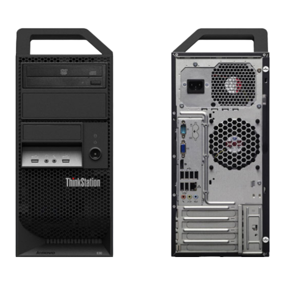
Figure 1. Front connector, control, and indicator locations Optical drive eject/close button USB connector (USB port 1) Hard disk drive activity indicator Headphone connector Power indicator Microphone connector Power switch USB connector (USB port 2) © Copyright Lenovo 2011... -
Page 74: Locating Connectors On The Rear Of Your Computer
Locating connectors on the rear of your computer Figure 2 “Rear connector locations” on page 68 shows the locations of the connectors on the rear of your computer. Some connectors on the rear of your computer are color-coded to help you determine where to connect the cables on your computer. - Page 75 Connector Description DisplayPort connector Used to attach a high-performance monitor, a direct-drive monitor, or other devices that use a DisplayPort connector. Note: The DisplayPort connector is not applicable on some models. If your computer has a graphics card installed, be sure to use a monitor connector on the graphics card.
-
Page 76: Locating Components
Locating components Figure 3 “Component locations” on page 70 shows the locations of the various components in your computer. To remove the computer cover, see “Removing the computer cover” on page 72. Figure 3. Component locations Heat sink and fan assembly Front fan assembly Microprocessor System board... -
Page 77: Locating Parts On The System Board
Locating parts on the system board Figure 4 “System board part locations” on page 71 shows the locations of the parts on the system board. Figure 4. System board part locations 4-pin power connector Front panel connector for power switch and LED indicators Microprocessor fan connector Front USB connector 1 (for connecting USB port 1 and 2 on the front bezel) -
Page 78: Removing The Computer Cover
Attention: Do not open your computer or attempt any repair before reading and understanding the “Important safety information” in the ThinkStation User Guide. To obtain a copy of the ThinkStation User Guide, go to: http://www.lenovo.com/ThinkStationUserGuides. This section provides instructions on how to remove the computer cover. -
Page 79: Removing And Reinstalling The Front Bezel
Attention: Do not open your computer or attempt any repair before reading and understanding the “Important safety information” in the ThinkStation User Guide. To obtain a copy of the ThinkStation User Guide, go to: http://www.lenovo.com/ThinkStationUserGuides. This section provides instructions on how to remove and reinstall the front bezel. -
Page 80: Installing Or Replacing A Pci Card
Attention: Do not open your computer or attempt any repair before reading and understanding the “Important safety information” in the ThinkStation User Guide. To obtain a copy of the ThinkStation User Guide, go to: http://www.lenovo.com/ThinkStationUserGuides. This section provides instructions on how to install or replace a PCI card. Your computer has two standard PCI card slots, one PCI Express x1 card slot, and one PCI Express x16 graphics card slot. - Page 81 3. At the rear of the computer, press the release button to open the card latch Figure 7. Opening the PCI card latch 4. Depending on whether you are installing or replacing a PCI card, do one of the following: •...
- Page 82 Figure 8. Removing a PCI card Notes: a. The card fits tightly into the card slot. If necessary, alternate moving each side of the card a small amount until it is removed from the card slot. b. If the card is held in place by a retaining latch, disengage the card retaining latch in either of the two ways illustrated, depending on the retaining latch on the PCI card slot.
-
Page 83: Installing Or Replacing A Memory Module
Attention: Do not open your computer or attempt any repair before reading and understanding the “Important safety information” in the ThinkStation User Guide. To obtain a copy of the ThinkStation User Guide, go to: http://www.lenovo.com/ThinkStationUserGuides. This section provides instructions on how to install or replace a memory module. - Page 84 4. Locate the memory slots. See “Locating parts on the system board” on page 71. 5. Remove any parts that might prevent your access to the memory slots. Depending on your computer model, you might need to remove the PCI Express x16 graphics card for easier access to the memory slots.
-
Page 85: Replacing The Battery
Attention: Do not open your computer or attempt any repair before reading and understanding the “Important safety information” in the ThinkStation User Guide. To obtain a copy of the ThinkStation User Guide, go to: http://www.lenovo.com/ThinkStationUserGuides. Your computer has a special type of memory that maintains the date, time, and settings for built-in features, such as parallel-port assignments (configuration). -
Page 86: Installing Or Replacing The Optical Drive
Attention: Do not open your computer or attempt any repair before reading and understanding the “Important safety information” in the ThinkStation User Guide. To obtain a copy of the ThinkStation User Guide, go to: http://www.lenovo.com/ThinkStationUserGuides. This section provides instructions on how to install or replace the optical drive. - Page 87 • If you are installing a secondary optical drive, remove the plastic panel in the front bezel for the drive bay you want to use. If there is a metal static shield installed in the drive bay, remove the metal static shield. •...
-
Page 88: Replacing The Card Reader
Replacing the card reader Attention: Do not open your computer or attempt any repair before reading and understanding the “Important safety information” in the ThinkStation User Guide. To obtain a copy of the ThinkStation User Guide, go to: http://www.lenovo.com/ThinkStationUserGuides. ThinkStation Hardware Maintenance Manual... - Page 89 This section provides instructions on how to install or replace the card reader. To replace the card reader, do the following: 1. Remove all media from the drives and turn off all attached devices and the computer. Then, disconnect all power cords from electrical outlets and disconnect all cables that are connected to the computer. 2.
-
Page 90: Replacing The Power Supply Assembly
Attention: Do not open your computer or attempt any repair before reading and understanding the “Important safety information” in the ThinkStation User Guide. To obtain a copy of the ThinkStation User Guide, go to: http://www.lenovo.com/ThinkStationUserGuides. This section provides instructions on how to replace the power supply assembly. - Page 91 DANGER Hazardous moving parts. Keep fingers and other body parts away. CAUTION: Never remove the cover on a power supply or any part that has the following label attached. Hazardous voltage, current, and energy levels are present inside any component that has this label attached.
-
Page 92: Replacing The Heat Sink And Fan Assembly
9. Install and tighten the four screws to secure the power supply assembly. Note: Use only screws provided by Lenovo. 10. Reconnect the power supply assembly cables to the system board and each of the drives. - Page 93 To replace the heat sink and fan assembly, do the following: 1. Turn off the computer and disconnect all power cords from electrical outlets. 2. Remove the computer cover. See “Removing the computer cover” on page 72. 3. Lay the computer on its side for easier access to the system board. 4.
-
Page 94: Replacing The Microprocessor
Attention: Do not open your computer or attempt any repair before reading and understanding the “Important safety information” in the ThinkStation User Guide. To obtain a copy of the ThinkStation User Guide, go to: http://www.lenovo.com/ThinkStationUserGuides. This section provides instructions on how to replace the microprocessor. - Page 95 5. Lift the small handle and open the retainer to access the microprocessor Figure 24. Accessing the microprocessor 6. Lift the microprocessor straight up and out of the microprocessor socket. Figure 25. Removing the microprocessor Notes: a. Your microprocessor and socket might look different from the one illustrated. Chapter 9 Replacing FRUs...
- Page 96 b. Note the orientation of the microprocessor in the socket. You can either look for the small triangle on one corner of the microprocessor or note the orientation of the notches on the microprocessor. This is important when installing the new microprocessor on the system board. c.
-
Page 97: Replacing The System Board
Attention: Do not open your computer or attempt any repair before reading and understanding the “Important safety information” in the ThinkStation User Guide. To obtain a copy of the ThinkStation User Guide, go to: http://www.lenovo.com/ThinkStationUserGuides. This section provides instructions on how to replace the system board. - Page 98 10. Remove the eight screws that secure the system board to the chassis by following the sequence shown in the following illustration. 11. Carefully lift the failing system board out of the chassis. 12. Position the new system board into the chassis so that the screw holes in the new system board are aligned with those in the chassis.
-
Page 99: Replacing The Primary Hard Disk Drive
Attention: Do not open your computer or attempt any repair before reading and understanding the “Important safety information” in the ThinkStation User Guide. To obtain a copy of the ThinkStation User Guide, go to: http://www.lenovo.com/ThinkStationUserGuides. This section provides instructions on how to replace the primary hard disk drive. - Page 100 5. Press the blue release tab down, slide the hard disk drive cage to the rear of the computer, and then pivot it outward. Figure 27. Removing the primary hard disk drive 6. Remove the hard disk drive cage from the chassis by sliding it outward. 7.
-
Page 101: Replacing The Secondary Hard Disk Drive
Attention: Do not open your computer or attempt any repair before reading and understanding the “Important safety information” in the ThinkStation User Guide. To obtain a copy of the ThinkStation User Guide, go to: http://www.lenovo.com/ThinkStationUserGuides. Note: Depending on your model type, your computer might come with a secondary hard disk drive bay for installing or replacing a secondary hard disk drive. - Page 102 2. Remove the computer cover. See “Removing the computer cover” on page 72. 3. Locate the secondary hard disk drive. 4. Disconnect the signal cable and the power cable from the hard disk drive. 5. Press the blue release button to release the hard disk drive cage from the chassis. Figure 30.
- Page 103 9. To install a new hard disk drive into the blue bracket, flex the bracket and align pin , pin , pin and pin on the bracket with the corresponding holes in the hard disk drive. Do not touch the circuit board on the bottom of the hard disk drive.
-
Page 104: Replacing The Front Fan Assembly
Attention: Do not open your computer or attempt any repair before reading and understanding the “Important safety information” in the ThinkStation User Guide. To obtain a copy of the ThinkStation User Guide, go to: http://www.lenovo.com/ThinkStationUserGuides. This section provides instructions on how to replace the front fan assembly. - Page 105 5. Release the two tabs that attach the front fan assembly to the chassis as shown and then completely remove the front fan from the chassis. Figure 33. Removing the front fan assembly Chapter 9 Replacing FRUs...
-
Page 106: Replacing The Rear Fan Assembly
Attention: Do not open your computer or attempt any repair before reading and understanding the “Important safety information” in the ThinkStation User Guide. To obtain a copy of the ThinkStation User Guide, go to: http://www.lenovo.com/ThinkStationUserGuides. This section provides instructions on how to replace the rear fan assembly. - Page 107 4. Disconnect the rear fan assembly cable from the rear fan connector on the system board. See “Locating parts on the system board” on page 71. 5. The rear fan assembly is attached to the chassis by four rubber mounts. Remove the rear fan assembly by breaking or cutting the rubber mounts and gently pulling the rear fan assembly out of the chassis.
-
Page 108: Completing The Parts Replacement
7. Pull on the tips of the rubber mounts until the rear fan assembly is secured in place. Figure 36. Installing the rear fan assembly 8. Connect the rear fan assembly cable to the rear fan connector on the system board. See “Locating parts on the system board”... - Page 109 9. To update your configuration, refer to Chapter 6 “Using the Setup Utility program” on page 37. Note: In most areas of the world, Lenovo requires the return of the defective Customer Replaceable Unit (CRU). Information about this will come with the CRU or will come a few days after the CRU arrives.
- Page 110 ThinkStation Hardware Maintenance Manual...
-
Page 111: Chapter 10. Fru Lists
Item # FRUs FRU # Heat sink, 73/95 watt • MT 7782: all models • MT 7783: all models 43N9700 • MT 7821: all models • MT 7823: all models • MT 7824: all models © Copyright Lenovo 2011... - Page 112 Item # FRUs FRU # Microprocessor, Xeon E3-1280 (3.50GHz / 4C / 8M / 1333 / 95w / T / 0GT) • MT 7782: CTO • MT 7783: CTO 15J 23M 56J 62J 65J 03T7045 • MT 7821: CTO • MT 7823: CTO •...
- Page 113 Item # FRUs FRU # Memory module, 4 GB ECC UDIMM (1333) • MT 7782: CTO • MT 7783: CTO 23M 32U 32F 33U 33F 34U 34F 35U 35F 36U 36F 37U 37F 38U 38F 39U 39F 41U 41F 42U 42F 43U 43F 44B 64Y9570 •...
- Page 114 Item # FRUs FRU # Optical drive, Blu-Ray DVD burner (SATA) • MT 7782: CTO • MT 7783: CTO 71Y7266 • MT 7821: CTO • MT 7823: CTO • MT 7824: CTO System board, Einstein 1.0 system board (TPM enabled) •...
- Page 115 Item # FRUs FRU # Hard disk drive, 500 GB SATA - 7200 rpm, 3 Gb/s, 16MB cache, 3.5" • MT 7782: CTO • MT 7783: CTO 24M 25G 31U 31F 32U 32F 33U 33F 34U 34F 35U 35F 36U 36F 37U 37F 38U 38F 39U 39F 41U 41F 42U 42F 43U 43F 44B 45C 46C 47C 48C 49V 52V •...
-
Page 116: Mechanical Frus
Item # FRUs FRU # Hard disk drive, 80 GB Solid State Drive (SSD) - MLC HDD, 2.5" • MT 7782: CTO • MT 7783: CTO 18M 03T7025 • MT 7821: CTO • MT 7823: CTO • MT 7824: CTO Hard disk drive, 160 GB SSD - MLC HDD, 2.5"... - Page 117 FRUs FRU # FRU, bezel kit • MT 7782: all models • MT 7783: all models 03W5421 • MT 7821: all models • MT 7823: all models • MT 7824: all models FRU, front and rear handle assembly, no handle cover •...
- Page 118 FRUs FRU # FRU, front fan assembly including mount and baffle • MT 7782: all models • MT 7783: all models 45K2306 • MT 7821: all models • MT 7823: all models • MT 7824: all models FRU, miscellaneous kit •...
- Page 119 FRUs FRU # FRU, optional HDD bracket assembly, without 4–pin cable • MT 7782: all models • MT 7783: all models 41R6106 • MT 7821: all models • MT 7823: all models • MT 7824: all models FRU, temperature sense cable (6–pin 460 mm) kit w/ bracket •...
-
Page 120: Keyboard And Mouse
• MT 7821: all models • MT 7823: all models • MT 7824: all models Keyboard and Mouse Keyboard (Lenovo Preferred Pro USB -- without hub) FRU # US English • MT 7782: CTO • MT 7783: CTO 16M 17M 18M 19M 21M 22M 23M 24M 31U 32U 33U 34U 35U 36U 37U... - Page 121 Keyboard (Lenovo Preferred Pro USB -- without hub) FRU # Arabic • MT 7782: CTO • MT 7783: CTO 25G 26G 27G 28G 29G 41A5290 • MT 7821: CTO • MT 7823: CTO • MT 7824: CTO 32G 33G 34G 35G 36G 37G 38G 39G 41G 42G 43G 44G 45G 46G 47G 48G 97G 98G 99G 81G •...
- Page 122 Keyboard (Lenovo Preferred Pro USB -- without hub) FRU # Chinese/US • MT 7782: CTO • MT 7783: CTO 44B 41A5296 • MT 7821: CTO • MT 7823: CTO • MT 7824: CTO 59B Czech (ABB) • MT 7782: CTO •...
- Page 123 Keyboard (Lenovo Preferred Pro USB -- without hub) FRU # French Canadian • MT 7782: CTO • MT 7783: CTO 31F 32F 33F 34F 35F36F 37F 38F 39F 41F 42F 43F 41A5302 • MT 7821: CTO • MT 7823: CTO •...
- Page 124 Keyboard (Lenovo Preferred Pro USB -- without hub) FRU # Iceland • MT 7782: CTO • MT 7783: CTO 25G 26G 27G 28G 29G 41A5308 • MT 7821: CTO • MT 7823: CTO • MT 7824: CTO 32G 33G 34G 35G 36G 37G 38G 39G 41G 42G 43G 44G 45G 46G 47G...
- Page 125 Keyboard (Lenovo Preferred Pro USB -- without hub) FRU # Polish • MT 7782: CTO • MT 7783: CTO 25G 26G 27G 28G 29G 41A5314 • MT 7821: CTO • MT 7823: CTO • MT 7824: CTO 32G 33G 34G 35G 36G 37G 38G 39G 41G 42G 43G 44G 45G 46G 47G...
- Page 126 Keyboard (Lenovo Preferred Pro USB -- without hub) FRU # Slovak • MT 7782: CTO • MT 7783: CTO 25G 26G 27G 28G 29G 41A5320 • MT 7821: CTO • MT 7823: CTO • MT 7824: CTO 32G 33G 34G 35G 36G 37G 38G 39G 41G 42G 43G 44G 45G 46G 47G...
- Page 127 Keyboard (Lenovo Preferred Pro USB -- without hub) FRU # Turkish • MT 7782: CTO • MT 7783: CTO 25G 26G 27G 28G 29G 41A5326 • MT 7821: CTO • MT 7823: CTO • MT 7824: CTO 32G 33G 34G 35G 36G 37G 38G 39G 41G 42G 43G 44G 45G 46G 47G...
- Page 128 Keyboard (Lenovo Fingerprint Reader USB) FRU # • MT 7782: CTO • MT 7783: CTO 41R0040 • MT 7821: CTO • MT 7823: CTO • MT 7824: CTO Belgium French • MT 7782: CTO • MT 7783: CTO 41R0041 • MT 7821: CTO •...
- Page 129 Keyboard (Lenovo Fingerprint Reader USB) FRU # Czech (ABB) • MT 7782: CTO • MT 7783: CTO 41R0046 • MT 7821: CTO • MT 7823: CTO • MT 7824: CTO Danish • MT 7782: CTO • MT 7783: CTO 41R0047 •...
- Page 130 Keyboard (Lenovo Fingerprint Reader USB) FRU # German • MT 7782: CTO • MT 7783: CTO 41R0052 • MT 7821: CTO • MT 7823: CTO • MT 7824: CTO Greek • MT 7782: CTO • MT 7783: CTO 41R0053 • MT 7821: CTO •...
- Page 131 Keyboard (Lenovo Fingerprint Reader USB) FRU # Italy • MT 7782: CTO • MT 7783: CTO 41R0058 • MT 7821: CTO • MT 7823: CTO • MT 7824: CTO Japanese • MT 7782: CTO • MT 7783: CTO 41R0059 • MT 7821: CTO •...
- Page 132 Keyboard (Lenovo Fingerprint Reader USB) FRU # Portuguese • MT 7782: CTO • MT 7783: CTO 41R0064 • MT 7821: CTO • MT 7823: CTO • MT 7824: CTO Romanian • MT 7782: CTO • MT 7783: CTO 41R0065 • MT 7821: CTO •...
- Page 133 Keyboard (Lenovo Fingerprint Reader USB) FRU # Spanish • MT 7782: CTO • MT 7783: CTO 41R0070 • MT 7821: CTO • MT 7823: CTO • MT 7824: CTO Swedish/Finnish • MT 7782: CTO • MT 7783: CTO 41R0071 • MT 7821: CTO •...
- Page 134 Keyboard (Lenovo Fingerprint Reader USB) FRU # UK English • MT 7782: CTO • MT 7783: CTO 41R0076 • MT 7821: CTO • MT 7823: CTO • MT 7824: CTO US Euro • MT 7782: CTO • MT 7783: CTO 41R0077 •...
- Page 135 Keyboard (Preferred Pro Full Size PS/2) FRU # • MT 7782: CTO • MT 7783: CTO 41A5042 • MT 7821: CTO • MT 7823: CTO • MT 7824: CTO Belgium English • MT 7782: CTO • MT 7783: CTO 41A5043 •...
- Page 136 Keyboard (Preferred Pro Full Size PS/2) FRU # Danish • MT 7782: CTO • MT 7783: CTO 41A5048 • MT 7821: CTO • MT 7823: CTO • MT 7824: CTO Dutch • MT 7782: CTO • MT 7783: CTO 41A5049 •...
- Page 137 Keyboard (Preferred Pro Full Size PS/2) FRU # Greek • MT 7782: CTO • MT 7783: CTO 41A5054 • MT 7821: CTO • MT 7823: CTO • MT 7824: CTO Greek/US • MT 7782: CTO • MT 7783: CTO 41A5080 •...
- Page 138 Keyboard (Preferred Pro Full Size PS/2) FRU # Japanese • MT 7782: CTO • MT 7783: CTO 41A5059 • MT 7821: CTO • MT 7823: CTO • MT 7824: CTO Korean • MT 7782: CTO • MT 7783: CTO 41A5060 •...
- Page 139 Keyboard (Preferred Pro Full Size PS/2) FRU # Romanian • MT 7782: CTO • MT 7783: CTO 41A5065 • MT 7821: CTO • MT 7823: CTO • MT 7824: CTO Russian/Cyrillic • MT 7782: CTO • MT 7783: CTO 41A5066 •...
- Page 140 Keyboard (Preferred Pro Full Size PS/2) FRU # SF/G • MT 7782: CTO • MT 7783: CTO 41A5071 • MT 7821: CTO • MT 7823: CTO • MT 7824: CTO Thailand • MT 7782: CTO • MT 7783: CTO 41A5072 •...
- Page 141 Keyboard (Enhanced Performance) FRU # US English • MT 7782: CTO • MT 7783: CTO 41A4961 • MT 7821: CTO • MT 7823: CTO • MT 7824: CTO Arabic • MT 7782: CTO • MT 7783: CTO 41A4962 • MT 7821: CTO •...
- Page 142 Keyboard (Enhanced Performance) FRU # Bulgarian • MT 7782: CTO • MT 7783: CTO 41A4967 • MT 7821: CTO • MT 7823: CTO • MT 7824: CTO Chinese/US • MT 7782: CTO • MT 7783: CTO 41A4968 • MT 7821: CTO •...
- Page 143 Keyboard (Enhanced Performance) FRU # French Canadian • MT 7782: CTO • MT 7783: CTO 41A4973 • MT 7821: CTO • MT 7823: CTO • MT 7824: CTO French Canadian • MT 7782: CTO • MT 7783: CTO 41A4974 • MT 7821: CTO •...
- Page 144 Keyboard (Enhanced Performance) FRU # Hungarian • MT 7782: CTO • MT 7783: CTO 41A4978 • MT 7821: CTO • MT 7823: CTO • MT 7824: CTO Iceland • MT 7782: CTO • MT 7783: CTO 41A4979 • MT 7821: CTO •...
- Page 145 Keyboard (Enhanced Performance) FRU # Norwegian • MT 7782: CTO • MT 7783: CTO 41A4984 • MT 7821: CTO • MT 7823: CTO • MT 7824: CTO Polish • MT 7782: CTO • MT 7783: CTO 41A4985 • MT 7821: CTO •...
- Page 146 Keyboard (Enhanced Performance) FRU # Slovak • MT 7782: CTO • MT 7783: CTO 41A4990 • MT 7821: CTO • MT 7823: CTO • MT 7824: CTO Spanish • MT 7782: CTO • MT 7783: CTO 41A4991 • MT 7821: CTO •...
- Page 147 Keyboard (Enhanced Performance) FRU # Turkish • MT 7782: CTO • MT 7783: CTO 41A4996 • MT 7821: CTO • MT 7823: CTO • MT 7824: CTO UK English • MT 7782: CTO • MT 7783: CTO 41A4997 • MT 7821: CTO •...
-
Page 148: Adapters And Miscellaneous Frus
Adapters and miscellaneous FRUs Adapters & Misc FRU # 256 MB NVIDIA NVS295 (2xDP) • MT 7782: CTO • MT 7783: CTO 49V 46R2782 • MT 7821: CTO • MT 7823: CTO • MT 7824: CTO 512M NVIDIA Quadro 400 (DVI+DP) •... - Page 149 Adapters & Misc FRU # DVI to VGA dongle • MT 7782: CTO • MT 7783: CTO 45C7816 • MT 7821: CTO • MT 7823: CTO • MT 7824: CTO DVI to VGA dongle • MT 7782: CTO • MT 7783: CTO 40Y7611 •...
-
Page 150: Power Cords
Adapters & Misc FRU # NVIDIA Quadro 2000 (Dual Link DVI+DP+DP) 1 GB GDDR5 • MT 7782: CTO • MT 7783: CTO 15J 21M 22M 23M 26G 41U 41F 43U 43F 56J 57J 58J 62J 63J 64J 65J 66J 67J 89Y8856 •... - Page 151 Power Cords -- primary FRU # Line Cord - Japan • MT 7782: CTO • MT 7783: CTO 11J 12J 13J 14J 15J 56J 57J 58J 59J 61J 62J 63J 64J 65J 66J 67J 41R3248 • MT 7821: CTO • MT 7823: CTO •...
- Page 152 Power Cords -- primary FRU # Line Cord - Taiwan • MT 7782: CTO • MT 7783: CTO 49V 52V 41R3278 • MT 7821: CTO • MT 7823: CTO • MT 7824: CTO Line Cord - Italy • MT 7782: CTO •...
- Page 153 Power Cords -- primary FRU # Line Cord - South Africa • MT 7782: CTO • MT 7783: CTO 16M 17M 18M 19M 21M 22M 23M 24M 25G 26G 27G 28G 29G • MT 7821: CTO 41R3220 • MT 7823: CTO •...
- Page 154 Power Cords --secondary FRU # Line Cord - Japan • MT 7782: CTO • MT 7783: CTO 11J 12J 13J 14J 15J 56J 57J 58J 59J 61J 62J 63J 64J 65J 66J 67J 41R3249 • MT 7821: CTO • MT 7823: CTO •...
- Page 155 Power Cords --secondary FRU # Line Cord - Taiwan • MT 7782: CTO • MT 7783: CTO 49V 52V 41R3279 • MT 7821: CTO • MT 7823: CTO • MT 7824: CTO Line Cord - Italy • MT 7782: CTO •...
-
Page 156: Recovery Discs
Power Cords --secondary FRU # Line Cord - South Africa • MT 7782: CTO • MT 7783: CTO 16M 17M 18M 19M 21M 22M 23M 24M 25G 26G 27G 28G 29G • MT 7821: CTO 41R3221 • MT 7823: CTO •... - Page 157 Windows 7 Professional 64 FRU # Chinese-Traditional (Taiwan) • MT 7782: CTO • MT 7783: CTO 49V 52V 03W2767 • MT 7821: CTO • MT 7823: CTO • MT 7824: CTO Czech • MT 7782: CTO • MT 7783: CTO 25G 26G 27G 28G 29G 03W2768 •...
- Page 158 Windows 7 Professional 64 FRU # Hebrew • MT 7782: CTO • MT 7783: CTO 25G 26G 27G 28G 29G 03W2791 • MT 7821: CTO • MT 7823: CTO • MT 7824: CTO 32G 33G 34G 35G 36G 37G 38G 39G 41G 42G 43G 44G 45G 46G 47G 48G 97G 98G 99G 81G Hong Kong •...
- Page 159 Windows 7 Professional 64 FRU # Polish • MT 7782: CTO • MT 7783: CTO 25G 26G 27G 28G 29G 03W2792 • MT 7821: CTO • MT 7823: CTO • MT 7824: CTO 32G 33G 34G 35G 36G 37G 38G 39G 41G 42G 43G 44G 45G 46G 47G 48G 97G 98G 99G 81G Portuguese •...
- Page 160 Windows 7 Professional 64 FRU # Serbian • MT 7782: CTO • MT 7783: CTO 25G 26G 27G 28G 29G 03W2783 • MT 7821: CTO • MT 7823: CTO • MT 7824: CTO 32G 33G 34G 35G 36G 37G 38G 39G 41G 42G 43G 44G 45G 46G 47G 48G 97G 98G 99G 81G Turkish •...
-
Page 161: Windows 7 Ultimate 64 Recovery Cd
Windows 7 Professional 64 FRU # C&L Croatian (EN/SL/CR) • MT 7782: CTO • MT 7783: CTO 25G 26G 27G 28G 29G 03W2788 • MT 7821: CTO • MT 7823: CTO • MT 7824: CTO 32G 33G 34G 35G 36G 37G 38G 39G 41G 42G 43G 44G 45G 46G 47G 48G 97G 98G 99G 81G Windows 7 Ultimate 64 Recovery CD Windows 7 Ultimate 64... - Page 162 ThinkStation Hardware Maintenance Manual...
-
Page 163: Chapter 11. Additional Service Information
• To determine the current Level of BIOS: – Start the Setup Utility program. • Sources for obtaining the latest level BIOS available 1. Lenovo support web site: http://www.lenovo.com/support 2. Lenovo Customer Support Center 3. Levels 1 and 2 Support To update (flash) the BIOS, see “Updating (flashing) the BIOS”... -
Page 164: Updating (Flashing) The Bios From Your Operating System
Updating (flashing) the BIOS from your operating system Note: Because Lenovo makes constant improvements to its Web sites, the Web page contents are subject to change without notice, including the contents referenced in the following procedure. -
Page 165: Power Management
6. Reconnect any cables that were disconnected and reinstall the PCI card if removed. 7. Reinstall the computer cover and reconnect the power cords for the computer and monitor to electrical outlets. See “Completing the parts replacement” on page 102. 8. - Page 166 ThinkStation Hardware Maintenance Manual...
-
Page 167: Appendix A. Notices
Lenovo representative for information on the products and services currently available in your area. Any reference to a Lenovo product, program, or service is not intended to state or imply that only that Lenovo product, program, or service may be used. Any functionally equivalent product, program, or service that does not infringe any Lenovo intellectual property right may be used instead. -
Page 168: Television Output Notice
The emission notices information is available in the ThinkStation Safety and Warranty Guide that came with your computer. Trademarks The following terms are trademarks of Lenovo in the United States, other countries, or both: Lenovo The Lenovo logo Rescue and Recovery... -
Page 169: Index
POST/BIOS power supply assembly, replacing flashing the BIOS Power-On, Password front connectors, controls, indicators front bezel front bezel, removing rear connectors front bezel, reinstalling rear fan assembly, replacing front fan assembly, replacing recovering © Copyright Lenovo 2011... - Page 170 from a POST/BIOS update failure recovery boot-block removing computer cover replacing battery card reader hard disk drive heat sink and fan assembly microprocessor security enabling or disabling selecting startup device temporary startup device serial port setting password settings changing viewing Setup Utility program Setup Utility program, starting Setup Utility, exiting...
- Page 172 Part Number: 0A74658 Printed in USA (1P) P/N: 0A74658 *0A74658*...
Need help?
Do you have a question about the ThinkStation E30 7824 and is the answer not in the manual?
Questions and answers