
Subscribe to Our Youtube Channel
Related Manuals for Shini SAL-UG124

Summary of Contents for Shini SAL-UG124
- Page 1 SAL-UG124 “One-to-Four” Separate Hopper Loader Date: May, 2023 Version: Ver.F (English)
-
Page 2: Table Of Contents
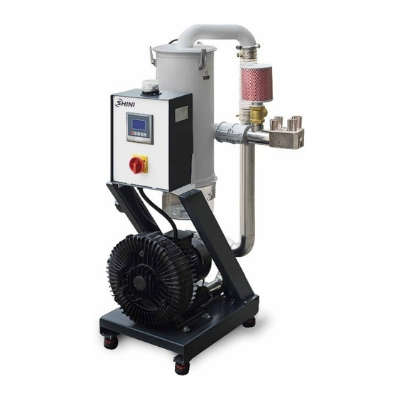
Contents General Description ..................4 1.1 Coding Principle ..................5 1.2 Feature ....................5 1.3 Loading Capacity ..................7 1.4 Safety Regulations .................. 7 1.4.1 Safety Signs and Labels ..............7 1.4.2 Signs and Labels ................8 1.5 Exemption Clause ................... 8 Structure Characteristics and Working Principle ........ - Page 3 6.5 Monthly Checking ................. 24 6.6 Maintenance Schedule ................. 25 6.6.1 About the Machine ..............25 6.6.2 Installation & Inspection .............. 25 6.6.3 Daily Checking ................25 6.6.4 Weekly Checking ................. 25 6.6.5 Monthly Checking ................ 25 Table Index Table 3-1:Compressed Air Specification ............11 Picture Index Picture1-1:SAL-5HP-UG124Main Unit + SHR-12U-S Hopper ......
-
Page 4: General Description
1. General Description Read this manual carefully before operation to prevent damage of the machine or personal injuries. "One-to-Four" Separate hopper loaders are designed and developed on the basis of original European separate-vacuum hopper Loaders. They have more functions, and are easy to operate and convenient to install. Collocated with four European vacuum hopper receivers SHR-U-S, it is suitable for conveying materials of two dehumidifying dryers (such as two-in-one SDD). -
Page 5: Coding Principle
SAL-UG124collocated with the European stainless steel central hopper to ensure no contamination of the materials. l SAL-UG124 models adopt LCD display + microcomputer controller to ensure intuitive display and easy operation. l SAL-UG124 series models have independent shut-off output function that can directly control the shut-off valve SBU. - Page 6 Chapter 6, which contains service instructions intended for service engineers. Other chapters contain instructions for the daily operator. Any modifications of the machine must be approved by SHINI in order to avoid personal injury and damage to machine. We shall not be liable for any damage caused by unauthorized change of the machine.
-
Page 7: Loading Capacity
1.3 Loading Capacity 16’ 49’ 82’ 115’ 148’ 180’ 213’ 246’ 279’ 312’ 3,000 6,614Ib/hr 13.1 ’ Height: 4m/ Bulk density: 0.65kg/ L 2,500 5,512Ib/hr Frequency: 60Hz 2,000 4,409Ib/hr 1,500 3,307Ib/hr 1,000 2,205Ib/hr 1,102Ib/hr Horizontal Distance (m) Picture 1-2: Loading Capacity 1.4 Safety Regulations Strictly abide by the following safety regulations to prevent damage of themachine or personal injuries. -
Page 8: Signs And Labels
Shini (including employees and agents). Shini is exempted from liability for any costs, fees, claims and losses caused by reasons below: 1. Any careless or man-made installations, operation and maintenances upon machines without referring to the Manual prior to machine using. -
Page 9: Structure Characteristics And Working Principle
2. Structure Characteristics and Working Principle 2.1 Main Functions SAL-UG "Euro" separate-vacuum hopper loader is applicable to convey plastic granule. Its principle is to make use of motor generated vacuum to form a pressure gap and to convey plastic material by this way. 2.1.1 Working Principle Diaphragm Diaphragm... -
Page 10: Installation And Debugging
3. Installation and Debugging This series of models can only be used in well-ventilated working environmen Read this chapter carefully before installation of the machine. Install the machine by following steps. Power supply should be fixed by qualified technicians! 3.1 Installation Space The notice of installation and positioning: 1) The machine can only be installed in a vertical position, so as to ensure there’re no pipes, fixed structures or other objects above and adjacent to... -
Page 11: Power Connection
3.2 Power Connection 1) Make sure the voltage and frequency of the power source comply with those indicated on the manufacturer nameplate that attached to the machine. 2) Power cable and earth connection should conform to your local regulations. 3) Use independent electrical wires and power switch. Diameter of electrical wire should not be less than those used in the control box. -
Page 12: Application And Operation
4. Application and Operation 4.1 Panel Description Hopper1 Hopper2 Hopper3 Hopper4 Picture4-1:Control Panel 12(25) -
Page 13: Parameter Setting
Symbol Name Meaning Description Startup ON/OFF Start/stop the machine /shutdown MENU Menu Enter or exit parameter setting Setting Modify or confirm machine parameters Move the menus down, and reduce the DOWN Down key value Move the menbus up, and increase the Up key value 4.2 Parameter Setting... - Page 14 Parameter Values Parameter Name Function Description Factory Range Default Hopper action the hopper is opened or closed start Preparation time Start thehopper, and it will work after the preparation time. 0-99S Suction time Suction valve action time 0-999S Shut-off time Shut-off valve action time 0-99S Spraying valve action time...
- Page 15 When the machine starts mixing, the layers of its mixing actions For example: the suction time is 20sec, the mixing proportion is 10%, the number of layers is 2, then the mixing action is 9s—1s ----9s---1s Set single layer‘s operation, and the suction time range is 5-99 secs. *Mixing method Set two layer‘s operation, and the suction time range is 17-99 secs.
- Page 16 Common Parameters(whole machine) Parameter Values Parameter Name Function Description Factory Default Range Set the times that materials not dropped into the Shortage counting alarm 0-99S hopper and for the alarm Vacuum breaking valve Vacuum breaking valve action time 0-999S The times of several repeated suctions before Host unit’s filter cleaning each 3次...
-
Page 17: Code Description
Check bit None parity odd even parity None Stop bit 1 bit 2 bit 4.3.1 Code Description suction motor running shut-off spraying standby waiting time motor overload D+time suction time N+time Motor delay stop time high pressure mixing valve 4.3.2 Action Specification Parameter Description Action Specification... -
Page 18: Communication Address(Protocol Modbus-Rtu
4.1 Communication Address(protocol modbus-RTU) Address Reading (keeping Default Min. Max. Parameters Unit deposit Writing Parameter Value Value zone) (decimal) Current action bit 0 shutdown bit 1 standby bit 2 absorb materials bit 3 wait for material discharge bit 4 cleaning the screen wait motor stopping... - Page 19 bit 6 alarm output 1 output output bit7~bit15 undefined Current action bit 0 shutdown bit 1 standby bit 2 absorbing materials bit 3 waiting for material discharge bit 4 clean the filter screen bit 5 wait for motor stop bit 6 filter blocking alarm bit 7 shortage alarm bit8~bit15 undefined Startup &...
- Page 20 Accumulating times of times material shortage alarm Startup & shutdown 1 shutdown control startup Current action bit 0 startup bit 1 standby bit 2 cleaning the filter screen bit 3 wait for motor stopping bit 4 absorb the material bit 5 absorb the masterbatch material (mixing) bit 6 wait for material...
-
Page 21: Trouble-Shooting
5. Trouble-shooting Failures Possible Causes Troubleshooting Power disconnected. Power on. Main power switch damaged. Replace the main power switch. Power cable fault. Check the power circuit. The controller doesn’t work or Check the cause of the tripping the panel is not on after Control circuit breaker tripped. -
Page 22: Maintenance And Repair
6. Maintenance and Repair Note: All the repair work should be done by professionals in order to prevent personal injuries and damage of the machine. 1. First, pull out the spraying air pipe, open the filter lid, take out the filte r, and use a high-pressure air gun to blow the dust on the filter from inside to outside. -
Page 23: Material Hopper
6.1 Material Hopper Clean material hopper periodically or when you find conveying capacity reduced. Please loose the spring clips, take down the hopper lid, and take out filter screen. Remove all the dusts and fines on filter screen and inside of material hopper. 6.2 Main Body Take out the air filter to make it clean periodically or when you find conveying capacity reduced. -
Page 24: Monthly Checking
immediately. 2) Check the function of the keys on the control panel. 3) Check if conveying hose connections at material inlet are loose or not, and if the seal ring is sealed up. Note: Cut off power supply when you check electrical wires. 6.5 Monthly Checking 1) Check if the clips of hopper lid are loose or not. -
Page 25: Maintenance Schedule
6.6 Maintenance Schedule 6.6.1 About the Machine Model Manufacture date Ф Voltage V Frequency Power 6.6.2 Installation & Inspection Check if the takeover pipe has been correctly connected. Check if that pipe is locked up by clips. Check if mounting base is locked tightly. Electrical Installation Voltage: Fuse melting current: One-phase: A...
Need help?
Do you have a question about the SAL-UG124 and is the answer not in the manual?
Questions and answers