Table of Contents
Advertisement
Quick Links
Advertisement
Table of Contents

Subscribe to Our Youtube Channel
Related Manuals for Orbis VIARIS CITY+

Summary of Contents for Orbis VIARIS CITY+
- Page 1 VIARIS CITY+ ELECTRIC VEHICLE SMART CHARGING POINT...
-
Page 2: Table Of Contents
INSTALLATION ..................6 EQUIPMENT POWERCONNECTION ........... 9 ADDITIONAL SECURITY PROTECTIONS ......... 11 COMPLETION OF INSTALLATION ............ 13 SETTINGS ..................14 LOAD MODULATION SYSTEM SPL-ORBIS ........20 RECHARGING PROCESS..............25 SHIPPERSTATES ................26 EXTRAS....................30 MAINTENANCE .................. 30 TECHNICAL CHARACTERISTICS ............. 31 DIMENSIONS .................. -
Page 3: Description
DESCRIPTION The VIARIS CITY+ is a smart charging point for electric vehicles that has two independent Type 2 socket outlets of 22 kW, in Mode 3 (EN 61851-1), protected by shutter and allowing fast charging of two vehicles. Built with high-thickness aluminum sheet with high heat and moisture resistance paint, it is especially suitable for outdoor use in public environments thanks to its high mechanical protection IK10. -
Page 4: General Attention
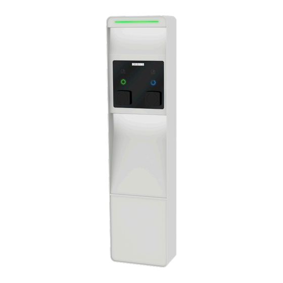
Standardized interfaces for integration in management platforms (OCPP 1.6 Json with Smart charging, Modbus TCP and RTU. MQTTS). Backend/OCPP connection via LAN, WLAN or LTE. Communication with the manager via WiFi, ethernet or 4G. OTA updateable firmware. ... - Page 5 Description of elements Charger status RFID RFID activation activation zone zone outlet 2 outlet 1 Lighting state of outlet 2 Lighting state of outlet 1 Type 2 socket outlet 2 Type 2 socket outlet 1 Installation base...
-
Page 6: Installation
INSTALLATION Safety warnings During the installation and operation of the equipment it is necessary to observe the following instructions: The equipment must be installed by authorized and qualified personnel who scrupulously comply with the instructions in this manual. The equipment must be installed and activated in compliance with the current low voltage regulation. -
Page 7: Installation Distances
Installation distances It is necessary to maintain about 0.5 meters from the walls or other obstacles for their accessibility and for maintenance tasks. Fixing to the ground The VIARIS CITY+ smart charging station is designed to be installed on a concrete bench using the supplied foundation kit. Foundation kit Template... - Page 8 Corrugated junction tube density of concrete B30 350 kg cement/m Once the kit has been installed and the concrete has been set, we proceed to fix the installation base in the threaded stems that are exposed, previously removing the four washers and four M12 nuts. Next, we fix the charging station using the eight supplied M8 washers and nuts.
-
Page 9: Equipment Powerconnection
EQUIPMENT POWER CONNECTION Before accessing the connection terminals, verify that the cables are not under electrical voltage. The opening of the envelope does not imply the absence of tension inside. Only authorized and qualified personnel may be opened. Make electrical connections according to the connection scheme. - Page 10 VIARIS CITY+ with protections included In charging stations with protections included, the connection will be unique because the separation between the lines of the two charging units is done internally. The phases of outlet 2 are internally rotated (L3, L1, L2). 44 kW 3PH+N 3x230/400 V~ NOTE: To make the electrical connection to the charger should be used...
-
Page 11: Additional Security Protections
ADDITIONAL SECURITY PROTECTIONS To ensure the electrical safety of the installation, each of the two charging units is equipped with a fail monitoring system of the switching device. In case of failure of the switching device of one line does not interfere with the other. - Page 12 Scheme 1 Outlet 2 Outlet 1 Scheme 2 At the entrance of the external protection phase firing the differential for outlet 2. At the entrance of the external protection phase firing the differential for outlet 1. Outlet 2 Outlet 1...
-
Page 13: Completion Of Installation
COMPLETION OF INSTALLATION Place the back cover and attach it with the supplied M5 screws. -
Page 14: Settings
SETTINGS To perform the configuration of the VIARIS CITY+ charging station you must connect to your web platform. The VIARIS CITY+ is a charging station with two socket outlets, each with a separate charging unit, so you must configure each unit separately, first the primary unit (outlet 1) and then the secondary one (outlet 2). - Page 15 Platform WEB We connect to the VIARIS CITY+ primary load unit via mobile device or PC using a web browser, following these steps: 1. Set up your device’s network and Internet connection to Wi-Fi. 2. You must connect to the ORB_EVVC5nnnnnnnnnnnnn (where nnnnnnnnnnnnn is the serial number).
- Page 16 7. To finish programming, click Overwrite. The computer will then restart.
-
Page 17: Ethernet Communication
Ethernet communication From the web platform we can configure the Ethernet connection. This configuration must be performed on both load units. Access this setting using the Settings menu > Networks (e). The VIARIS CITY+ is supplied by default with DHCP enabled (f) (dynamic IP allocation), so this configuration would not be necessary. -
Page 18: Rfid, Cards
RFID, cards In the menu Settings > Touch/RFID (h) we can perform the management of highs (i) and lows (j) of authorized RFID cards. Note: All VIARIS CITY+ are supplied from the factory with a set of 5 RFID cards that are preloaded in each of the two socket sockets. Clicking on the add cards icon (i) the sectors of the load unit that we are setting up will light up blinking white. - Page 19 Communication OCPP To connect a VIARIS CITY+ to an OCPP platform or backend it is necessary to configure each of the two socket bases with the URL of the platform and the corresponding endpoint, an endpoint for each of the outlets. As indicated in the following image, emphasize that both the URL and the endpoint will be entered in the URL section.
- Page 20 Configuration Wi-Fi access point If the VIARIS CITY+ is installed on a public environments, once the configuration process is finished, for security issues, it is recommended to change the password of the Wi-Fi access point or disable it as indicated below. Change password In Networks >...
-
Page 21: Load Modulation System Spl-Orbis
LOAD MODULATION SYSTEM SPL-ORBIS The SPL-ORBIS performs modulation by measuring the total power of the installation to distribute it proportionally to all VIARIS chargers within the network. It consists of a Network Analyzer, a VIARIS CITY+ charging station with its main charging unit acting as Master Charger, and one or more charging stations with its charging units operating as slave chargers, communicated to each other via an RS-485 network. - Page 22 Cable A very important element is the type of cable used to make the bus. For RS-485 connections, a braided or shielded pair of 0.15 to 0.50 mm section may be used. Special care should be taken to avoid contact between the wires of the conductors.
- Page 23 The rest of the chargers that integrate the SPL system must be configured, both sockets, in slave mode (p) assigning to each outlet the charge current in front of error (q). Once done, click Overwrite (r). The computer will then restart. In order to optimize the load and management of the contracted power, especially if loads of vehicles with single or two-phase in-board charger are carried out, it is recommended to perform a phase rotation as...
- Page 24 This rotation must be reflected in the configuration of each shot. SPL monitor From the Master charger, we will have access to the SPL Monitor, where we can see all the consumption data of the installation and independently, the display of all cars and chargers.
-
Page 25: Recharging Process
RECHARGING PROCESS Start the loading of the vehicle Make sure the charger has a free outlet. The status bar will be lit in green. Connect the electric vehicle to the smart charger. Keep the RFID card near the activation zone until you hear a ... -
Page 26: Shipperstates
SHIPPERSTATES The VIARIS CITY+ charging station is composed of two Type 2 outlet bases that operate independently. The status bar will be lit in green as long as one of the two shots is available. When the two shots are occupied it will light up in red. - Page 27 RFID: Vehicle connected to Green blinking charger socket, but without charging Sectors: permit Green blinking RFID: Shutdown Vehicle connected to charger socket and Sectors: with charging permit Fixed blue RFID: Shutdown Vehicle loading Sectors: Blue moving from top to bottom...
- Page 28 RFID: Shutdown Loading of the complete vehicle Sectors: Blue blinking RFID: Shutdown Charger reserved via management Sectors: platform Fixed white RFID: Shutdown Update of Firmware/software in progress Sectors: White blinking...
- Page 29 RFID: Error – attention re- Shutdown dear (see table PROBLEM Sectors: RESOLUTION) Red fluctuating...
-
Page 30: Extras
EXTRAS The VIARIS CITY+ can incorporate, depending on the model: Magnetothermal electric protections + differential Magnetothermal protection suitable to the current of the intelligent charger incorporating differential current protection. Made the electrical installation check the operation of the differential by pressing its test button. -
Page 31: Technical Characteristics
TECHNICAL CHARACTERISTICS Feeding Nominal frequency | according to feature label Power Own consumption In vacuum Load function 14 W Charging modes (depending on model) Mode 3 according to EN 61851-1 Connection Base Type Charging mode according to EN 62196-2 Wi-Fi communication 802.11 b/g/n Closure of the envelope By means of screws... -
Page 32: Dimensions
DIMENSIONS... -
Page 33: Problemsolving
PROBLEMSOLVING Problem Resolution The charger is powered and no Check the power according to the outlet connected and with the connection scheme and that the status bar and LED indicators protections are on. turned off. Wait approximately 10 seconds for the charger to boot. Vehicle connected to a charger There is no communication outlet and its LED indicator is... - Page 34 Vehicle connected to a charger The vehicle has finished outlet and its LED indicator is charging, check that the battery is in blinking blue and does not full or that the vehicle does not charge. have a time schedule. Vehicle connected to a charger Error;...
- Page 35 After the charging process, the Perform Reset: rearrange the vehicle is still connected to the protections and restart the charger with the plug locked in charger to remove the plug. the socket base, and its LED indicator is fixed green Exceeding maximum power Adjust the maximum power of the charger as indicated in the item...
-
Page 36: Referencedirectives And Standards
ORBIS TECNOLOGÍA ELÉCTRICA S.A. hereby declares that the type of radio equipment VIARIS CITY+ complies with Directive 2014/53/EU. The full text of the EU declaration of conformity is available at the following internet address: http://www.orbis.es/descargas/declaraciones-de-conformidad...
Need help?
Do you have a question about the VIARIS CITY+ and is the answer not in the manual?
Questions and answers