Table of Contents
Advertisement
Quick Links
Advertisement
Table of Contents

Related Manuals for BAC Vertex VRC-A-1012N Series

Summary of Contents for BAC Vertex VRC-A-1012N Series
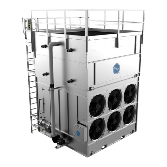
- Page 1 ® Vertex Evaporative Condenser RIGGING & ASSEMBLY INSTRUCTIONS...
- Page 2 If you do not have a copy of this drawing, or if you need additional information about this unit, contact your local BAC Representative whose name and telephone number are on a label adjacent to the access door. The model number and serial number of the unit are also located in this area.
-
Page 3: Table Of Contents
® Vertex Evaporative Condenser RIGGING & ASSEMBLY INSTRUCTIONS Contents 1. Introduction ........................................4 Safety ........................................... 4 Shipping ........................................4 Pre-Rigging Checks ....................................4 Unit Weights ......................................5 Anchoring ....................................... 5 Cold Weather Operation ..................................... 5 Location ........................................5 Warranties ........................................5 Unit Operation ...................................... -
Page 4: Introduction
Evaporative Condensers are factory assembled to ensure uniform quality with minimum field assembly. As ® standard, models ship in two sections per cell (lower and upper). Contact your local BAC Representative for more information. For the dimensions and weights of a specific unit or section, refer to the submittal drawings. -
Page 5: Unit Weights
Each unit must be located and positioned to prevent the introduction of discharge air into the ventilation systems of the building on which the unit is located and of adjacent buildings. For detailed recommendations on BAC equipment layout, see our website at www.BaltimoreAircoil.com... -
Page 6: Rigging & Assembly
2. Rigging & Assembly Rigging Refer to Table 1 for the recommended vertical dimension “H” from the lifting device to the spreader bar. In the event of extended lifts or where hazards exist, the lifting devices should be used in conjunction with safety slings placed under the unit. Casing Section or Single Basin Section Piece Lift... - Page 7 Figure 1. Single-Piece Lift Rigging of Upper Coil Section Center of Gravity Rigging of Lower Fan Section Figure 2. Two-Piece Lift Vertex Evaporative Condenser Rigging & Assembly Instructions - Rigging & Assembly Page | 7 ®...
-
Page 8: Section Assembly
Install sealer tape on the mating flange of the bottom section to ensure an airtight seal between the top and bottom section. Install flat butyl sealer tape (BAC part #554000) supplied with the unit, on the mating flanges of the lower section in a continuous line. - Page 9 Fasten the hardware between the coil casing and lower section per Figure 5. Lower the coil casing section the rest of the way onto the lower section, keeping mounting holes aligned. Figure 5. Fastening of Upper and Lower Sections Secure the hose connecting the sections of the pump discharge pipe with the hose clamps provided. On units with more than one casing, install the remaining casings using the same procedure as the first.
-
Page 10: Wiring The Factory Terminal Box (Ec Fan System Only)
Refer to the equipment submittal drawings for the appropriate wiring diagram. The controls wiring should be provided in a separate conduit from any power wiring. BAC recommends penetrating the control panel from the bottom of the enclosure observing standards. It is also recommended to use shielded wire to avoid interference. Field wiring knockouts are shipped from the factory with NEMA 4 plugs in the holes. -
Page 11: Optional Accessory Installation
3. Optional Accessory Installation Bottom Water Outlet The bottom connection seal, Figure 8, is typical for all bottom remote sump outlets. Flange mounting hardware and gasket to be supplied by others. Bottom connection seal kit(s) ship in plastic tubs. Figure 6. Bottom Water Outlet Vertex Evaporative Condenser Rigging &... -
Page 12: Offset Access Platform, Perimeter Guardrail And Ladder
Offset Access Platform, Perimeter Guardrail and Ladder Overview External access platforms, perimeter handrails, ladders and ladder safety cages ship loose for field assembly and installation. Assembly and installation means and methods is dependent on the external access configuration selected. Please refer to the equipment submittal package for the selected external access configuration. - Page 13 Figure 9. Typ. Ladder & Bracket Installation Figure 10. Typ. End Ladder & Bracket Installation Vertex Evaporative Condenser Rigging & Assembly Instructions – Optional Accessory Installation ® Page | 13...
- Page 14 If the ladder is shipped in two sections assemble ladder sections together using supplied hardware. The shorter ladder section will be installed towards the top of the unit. See Figure 11. NOTE: For platform and ladder options ordered but not listed, refer to the customer information packet supplied on the unit.
- Page 15 Corner Vertical Rail Post Detail B – Rail Corner Connection Upper: Qty. (4) 5/16” bolt, flatwashers, lockwasher, nut Lower: Qty. (4) 3/8” bolt, flatwashers, lockwasher, nut Detail C – Rail to Rail Connection Qty. (1) 5/16” bolt, flatwashers, lockwasher, nut Detail A –...
-
Page 16: Offset Access Platform Assembly For 18' Units
Offset Access Platform Assembly for 18’ Units Platforms for 18’ spans may ship in two sections, each roughly 10 ft in length, which should be joined prior to lifting and installing on the unit. Unbolt the splice plates from both sides of the platform, but DO NOT remove the plates from the support beam channel. Slide the loose plates to the locations shown in Figure 15, Detail A and B. - Page 17 Begin joining the platform sections by offsetting the sections from each other as shown in Figure 16. Figure 14. Platform Assembly Offset Slide the platforms until the crossmember cutout is aligned with the crossmember of the second section. Then slide the two sections together until the support beams are aligned, and the crossmember is seated into the cutout.
- Page 18 Secure crossbeam on inside of platform with provided hardware. Figure 17. Inside beam splice plate and crossbeam mounting fastener locations Figure 18. Outside beam splice plate mounting fastener locations Vertex Evaporative Condenser Rigging & Assembly Instructions – Optional Accessory Installation ®...
- Page 19 Follow all steps in Section “Typical Installation”. Install A-frame handrail section and toeboard. See Figure 14 and Figure 21. Detail A – Field Installed A-Frame Handrail Section Figure 19. Platform and A-Frame Handrail Section Installation Detail B – Fastening A-Frame Handrail Section Vertex Evaporative Condenser Rigging &...
-
Page 20: Gap Cover Plate Installation
Gap Cover Plate Installation After platform installation is complete secure platform gap cover plates (PCC) to platform base using 5/16” tappers and 1/4” x 2” self-tapping screws provided. Secure coil casing section gap cover plate (FAT) to coil casing section using 1/4” x 2”... -
Page 21: Ladder Safety Cage
Ladder Safety Cage If the safety cage is shipped in multiple pieces assemble the bottom flared section to the upper safety cage section. Secure with supplied hardware. See Figure 23. NOTE: Safety gates are provided for all handrail openings, and all components are designed to meet OSHA requirements. - Page 22 Bolt the safety cage to the ladder using flat washers and locknuts. Orient all fasteners with bolt heads inside safety cage. See Figure 24, Detail A through D and refer to Table 2 for the quantity of bolting locations for different safety cage heights.
-
Page 23: Automatic Bearing Greasers (Optional For Baltidrive ® Power Train Units Only)
Automatic Bearing Greasers (Optional for BALTIDRIVE ® Power Train Units Only) Verify the mounting brackets are factory installed. Fill the extended lube lines with BAC compatible water resistant grease using a manual grease gun. See the “Fan Shaft Bearings” section of the Vertex ®... -
Page 24: Heater Control Panel
If leakage or condensation is likely to occur in the conduit runs leading to the control panel, install a drain in the bottom of the control panel and form a conduit loop. Verify operation by following the "Stand Alone BAC Heater Control Panel" in the Vertex ®... - Page 25 Figure 24. Example Wiring Diagram for Stand Alone BAC Heater Control Panel (Refer to Submittal Drawing for Specific Wiring Diagram) NOTE: Figure 26 is superseded by any drawing supplied with the panel by the manufacturer. Vertex Evaporative Condenser Rigging & Assembly Instructions – Optional Accessory Installation ®...
- Page 26 ® Vertex Evaporative Condenser RIGGING & ASSEMBLY INSTRUCTIONS baltimoreaircoil.com ©2023 Baltimore Aircoil Company | 7600 Dorsey Run Road | Jessup, MD 20794 | 410.799.6200 | RGRAVRCA01_R6.0...
Need help?
Do you have a question about the Vertex VRC-A-1012N Series and is the answer not in the manual?
Questions and answers