
Related Manuals for Saris RTL 84101320

Summary of Contents for Saris RTL 84101320
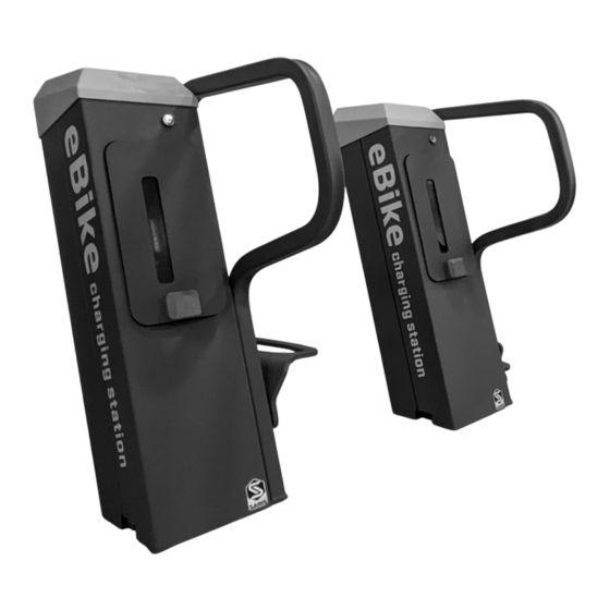
- Page 1 EBIKE CHARGING STATION DISCOVER MORE For more Saris INSTALLATION GUIDE Infrastructure products, scan the QR code or visit sarisinfrastructure.com www.rtl.co.nz 0800 785 744 sales@rtl.co.nz...
- Page 2 Tell Us What You Think! Sarisinfrastructure.com/product/ebike-charging-station Submit Your Installation Photos! Nothing makes us happier than seeing our infrastructure products out in the wild! Submit your photos at the link below. www.sarisinfrastructure.com/contact/submit-photos www.rtl.co.nz 0800 785 744 sales@rtl.co.nz...
- Page 3 120V or 240V outlet and space for securing each user’s personal bike charger. Please be sure to read and understand the following instructions before beginning your installation. Everyone here at Saris wants you to be happy with this product. Please contact us at sales@sarisinfrastructure.com or 800-783-7257 should you need anything.
- Page 4 Site Prep Shelter requirements: • Saris recommends a roof or shelter to provide added protection against sun (heat) and rain for the charging connection at the e-bike. Electrical requirements: • Power must be supplied to the charging station. This power needs to...
-
Page 5: Installation Instructions
Installation Instructions 1. Review site layout document to determine required space and setbacks for charging stations. 2. Determine power source for site. Main power should be connected to a circuit breaker. www.rtl.co.nz 0800 785 744 sales@rtl.co.nz... - Page 6 Site layout: Ground Mount System Notes: 1. All units in inches. 2. Power to be stubbed in from below dock or through knockout panel. www.rtl.co.nz 0800 785 744 sales@rtl.co.nz...
-
Page 7: Tools Required
Installation Instructions (base plate mount) Ground Mount System Components ANCHORS • 3/8” OR M10 Anchors (can be purchased from Saris Infrastructure, part #28879) QTY 4 per Dock OPTIONAL WHEEL HOLDER FOR BIKE HEIGHT STAGGERING (PURCHASED SEPARATELY, PART #34458) TOOLS REQUIRED •... - Page 8 Remove rear panel and mark the docks for anchoring. Remove the docks and install the anchors per manufacturer’s instructions. Installation instructions for optional Saris concrete anchors on following pages. Anchor holes and electrical connection opening dimensions from below: Bottom anchoring plate dimensions 5.
- Page 9 6. When fastening to solid concrete with a drop-in anchor, a hole must first be drilled into the concrete using a hammer drill, as this will drill the best quality hole. Once the bit is inserted into the hammer drill, the depth of the hole to be drilled can easily be set by using the depth gauge on the drill or by wrapping the bit with tape at the required depth.
- Page 10 7. Before proceeding with installation, the hole must be cleaned of all concrete dust to ensure proper fastening. Use a wire brush, vacuum, or compressed air to clean out the hole completely. Tool to remove debris after drilling holes. Installer provides. 8.
- Page 11 10. Reinstall the docks into position. Before securing the anchors, make sure to place conduit pieces between the docks, then tighten the anchor hardware. 11. Install wheel holders if applicable on each dock, noting the correct orientation of the wheel holder. Remove pin torx bolts and insert the carriage bolts through the wheel holder into the dock.
-
Page 12: Correct Orientation
13. Ensure the wheel holder is installed in the correct orientation. CORRECT ORIENTATION 14. Wire mains power to the junction box in the dock per legal codes. Terminal blocks are marked for Line, Neutral, and Ground connections. Power can be plumbed up from below the unit or through a knockout placed in the rear of the unit to the right of the access panel. -
Page 13: Electrical Specs
Electrical Specs www.rtl.co.nz 0800 785 744 sales@rtl.co.nz... - Page 14 Standard User Instructions 1. Park bike at dock using the wheel holder. 2. Lock bicycle frame with U-lock. 3. Gain access to locker with key. Keys will typically be supplied/controlled by a property manager or similar authority. 4. Place charger into the locker and plug into the provided receptacle. 5.
-
Page 15: Lock Mechanism
Lock Mechanism • Locker can be secured with any standard padlock. • Push door closed to activate latch. • To open, rotate the upper latch to the right to release the door latch. www.rtl.co.nz 0800 785 744 sales@rtl.co.nz... -
Page 16: Warranty
(3) its failure resulted from a defect in material or workmanship and not from normal wear expected in the use of the product; (4) the product or part is delivered, freight prepaid, to Saris Infrastruc- ture.
Need help?
Do you have a question about the RTL 84101320 and is the answer not in the manual?
Questions and answers