Advertisement
Quick Links
Advertisement

Related Manuals for REA JET HR pro OEM

Summary of Contents for REA JET HR pro OEM
- Page 1 User Manual REA JET HR Version 1.0 · Issue 3/9/18...
- Page 2 Although this documentation has been compiled with utmost care, some information may be incorrect or contain errors. REA Elektronik GmbH assumes no responsibility and shall not be liable for any damage that may result from mistakes or omissions contained in this document.
-
Page 3: Table Of Contents
Handling ......................10 Obligations of the operator .................10 Obligations of staff .....................11 Proper use ......................11 Foreseeable misuse ...................12 Hazards in handling the REA JET HR pro OEM ..........12 Electrical hazards ....................13 Fire and explosion hazards ................13 2.10 Hazard due to ink ....................13 Delivery ........................16... - Page 4 Other LED activities ..............42 4.4.9 Status LEDs of the print head connections 1 to 4 (X11 and X12, X21 and X22)......................43 Operating elements ....................44 4.5.1 Overview ....................44 Operating instructions REA JET HR pro OEM Page V 1.0 3/9/18 Copyright © REA Elektronik GmbH...
- Page 5 Important notes ....................59 Care ........................59 Maintenance ......................60 6.3.1 General notes ..................60 6.3.2 Screw, clamp and cable connections ............60 6.3.3 REA JET HR print heads ..............61 6.3.4 REA JET HR parallelograms ..............61 Shutdown ........................62 Short-term ......................62 Medium-term ......................62 Final ........................62 Operating instructions...
-
Page 6: Symbols Used In This Manual
This symbol indicates dangers which, if not avoided, may result in property damage. Achtung Dieses Symbol weist auf Gefahren hin, welche möglicherweise zu Sachschäden führen können. Operating instructions REA JET HR pro OEM Page V 1.0 3/9/18 Copyright © REA Elektronik GmbH... - Page 7 References to this manual and other documents are marked with a book icon. Maintenance information This symbol indicates information to ensure proper maintenance and cleaning. Operating instructions REA JET HR pro OEM Page V 1.0 3/9/18 Copyright © REA Elektronik GmbH...
- Page 8 Information This symbol indicates useful information that may make operation easier and improve production processes. This symbol indicates tips on handling the equipment. Operating instructions REA JET HR pro OEM Page V 1.0 3/9/18 Copyright © REA Elektronik GmbH...
-
Page 9: Safety Instructions
It must be ensured that no water, vapor or steam enters electrical control cabinets. Failure to observe this can endanger life and limb (danger of death due to electrocution)! Operating instructions REA JET HR pro OEM Page V 1.0 3/9/18 Copyright © REA Elektronik GmbH... -
Page 10: Handling
The locally applicable accident prevention regulations shall be complied with. 2.3 Obligations of the operator The operator undertakes to ensure that all persons working with the REA JET HR pro OEM and associated components have been instructed in the fundamental regulations on occupational safety and accident prevention,... -
Page 11: Obligations Of Staff
(packaging, products, semi-finished products etc.). Any use beyond or differing from the above applications is considered improper use. REA Elektronik GmbH explicitly declines all liability for any damage resulting from such use. -
Page 12: Foreseeable Misuse
REA JET HR pro OEM for its intended purpose only. If you have any questions or problems with regard to coding and marking, please contact REA Elektronik GmbH or its distributors. Never point the print head towards persons or animals! Ejected ink can irritate the eyes and/or skin. -
Page 13: Electrical Hazards
15 minutes with plenty of water and soap. Special cleaning pastes are available for cleaning skin. In the event of skin irritations, consult a doctor. Operating instructions REA JET HR pro OEM Page V 1.0 3/9/18 Copyright © REA Elektronik GmbH... - Page 14 Always wear safety glasses when working with ink or cleaners. Use safety glasses with side shields (or equivalent protection) when working with ink or cleaners. Operating instructions REA JET HR pro OEM Page V 1.0 3/9/18 Copyright © REA Elektronik GmbH...
- Page 15 For further information please contact your company’s security officer, who will provide you with details about the company’s disposal concepts, storage locations and workplace safety. Operating instructions REA JET HR pro OEM Page V 1.0 3/9/18 Copyright © REA Elektronik GmbH...
-
Page 16: Delivery
3.2 Transport 3.2.1 General notes The high-quality devices from REA Elektronik GmbH are delivered in specially adapted transport packages. These are intended to ensure that the equipment reaches you in perfect condition. To prevent damage to the package contents, avoid strong mechanical influences (such as impacts, vibrations, etc.) and moisture. -
Page 17: Intermediate Storage
Vibration Acceleration resistant up to 0.7 g 10 Hz ... 150 Hz If you have any further questions about transport, please contact REA Elektronik GmbH or your distributor. 3.2.2 Intermediate storage For intermediate storage, leave the equipment in its original package. -
Page 18: Handling
As general rule, only the original packaging and packaging material should be used for return shipments. If the original packaging and packaging materials are no longer available, please contact REA Elektronik GmbH to request replacement packaging. If you have any further questions about packaging and transport safety, please contact REA Elektronik GmbH. 3.3.4 Unpacking To avoid damaging the components, open the transport packaging carefully without using any pointed or sharp objects. -
Page 19: Disposal Of The Packaging
Please recycle any packaging materials that are no longer needed. Alternatively, you can also return them to the manufacturer. We recommend keeping at least one set of packaging for storage and transport purposes. Operating instructions REA JET HR pro OEM Page V 1.0 3/9/18 Copyright © REA Elektronik GmbH... -
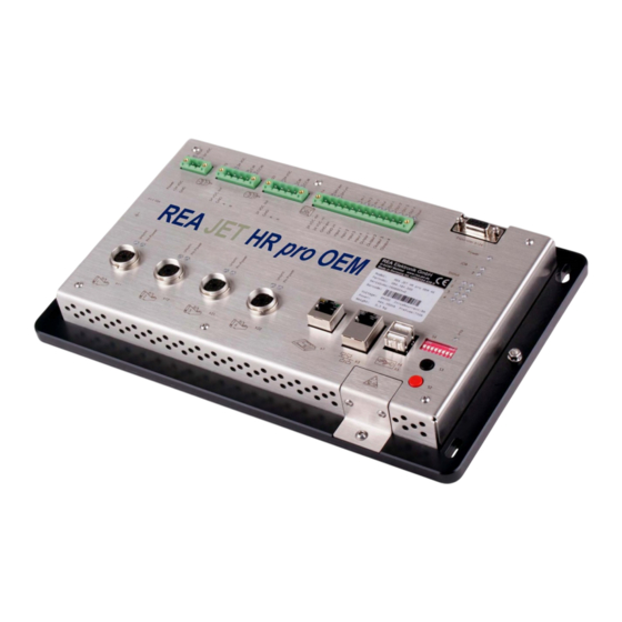
Page 20: Rea Jet Hr Pro Oem Controller
4 REA JET HR pro OEM controller 4.1 Technical specifications Parameters Value Dimensions 310 x 36 x 195 (W x H x D in mm) Weight 2.8 kg Connections 1 voltage supply connection 2 shaft encoder connections 4 digital inputs... -
Page 21: Mechanical Specifications
4.2 Mechanical specifications REA JET HR pro OEM controller – mechanical data Operating instructions REA JET HR pro OEM Page V 1.0 3/9/18 Copyright © REA Elektronik GmbH... -
Page 22: Electrical Connections
4.3 Electrical connections 4.3.1 Overview X124 REA JET HR pro OEM controller – electrical connections Description Voltage supply connection Grounding bolt Ethernet connection USB connection 1 USB connection 2 Terminal connection Operating instructions REA JET HR pro OEM Page V 1.0 3/9/18... -
Page 23: Voltage Supply Connection (X1)
Fuse The connections are described in detail below, from left to right and from top to bottom. 4.3.2 Voltage supply connection (X1) REA JET HR pro OEM controller – voltage supply connection REA JET HR pro OEM controller is operated with 24 V DC from a SELV power supply unit. -
Page 24: Shaft Encoder Connections 1 And 2 (X13 And X23)
4.3.3 Shaft encoder connections 1 and 2 (X13 and X23) REA JET HR pro OEM controller – shaft encoder connections 1 and 2 When connecting a shaft encoder, always observe the power ratings (24 V, etc.) and the interface type. -
Page 25: Electrical Limit Values
24 V DC, +/- 10 % for supply to the shaft encoder Maximum permissible output voltage load 100 mA out max. on the REA JET HR pro OEM by the shaft encoder Input voltage “Low level” < 3 V DC, sensitive in L Input voltage “High level”... -
Page 26: Digital Inputs And Outputs (X14)
Only push/pull or PNP types Maximum approx. 200 kHz 4.3.4 Digital inputs and outputs (X14) REA JET HR pro OEM controller – digital inputs and outputs The hardware (electronic circuit) for the digital inputs and outputs of REA JET HR pro OEM is galvanically isolated from the rest of the controller. -
Page 27: Electrical Limit Values
Electrical limit values 4.3.4.2.1 General information Parameters Designation/function Value Output voltage of REA JET HR pro OEM 24 V DC, +/- 10 % Maximum load of the outputs of the 700 mA total max. JET HR pro OEM (load current) -
Page 28: Outputs
< 0.5 µs min. All inputs must be designed as “plus” active digital 24V (12V) DC inputs. The digital inputs can be assigned different functions. Operating instructions REA JET HR pro OEM Page V 1.0 3/9/18 Copyright © REA Elektronik GmbH... -
Page 29: Extension Connection Of Digital Inputs And Outputs (X124)
4.3.5 Extension connection of digital inputs and outputs (X124) REA JET HR pro OEM controller – extension connection for digital inputs and outputs The digital inputs and outputs can be extended by connecting an additional module. REA JET HR pro OEM controller –... -
Page 30: Grounding Bolt (X2)
4.3.7 Grounding bolt (X2) REA JET HR pro OEM controller – grounding bolt Always observe the applicable regulations when connecting the protective conductor. The wiring must always run radially to the central “grounding point” of the machine/plant (= separate cable from each component). -
Page 31: Pin Assignment
The print head cables have a symmetrical design (= no specified direction of use). 4.3.8.1 Pin assignment REA JET HR pro OEM controller – designation of print head connector pins Designation Function Value Internal ground Ground Ground logic and product sensor... -
Page 32: Terminal Connection (X7)
4.3.9 Terminal connection (X7) REA JET HR pro OEM controller – terminal connection The terminal connection allows an input terminal to be connected to the REA JET HR pro OEM. The device outputs a repeated acoustic signal when the terminal cable is plugged in and a single signal when it is unplugged. -
Page 33: Pin Assignment
The device outputs an acoustic signal when USB storage media is plugged in or unplugged. 4.3.11.1 Pin assignment REA JET HR pro OEM controller – designation of USB connector pins Designation/function Value Supply voltage for the external USB device + 5 V DC... -
Page 34: Display Elements
4.4 Display elements 4.4.1 Overview REA JET HR pro OEM controller – display elements Description Status LEDs of voltage supply connection (X1) Status LEDs of shaft encoder connection 1 (X13) Status LEDs of shaft encoder connection2 (X23) Status LEDs of digital inputs and outputs (X14) -
Page 35: Status Leds Of The Voltage Supply Connection (X1)
The activities of the status LEDs are described in detail below, from left to right and from top to bottom. 4.4.2 Status LEDs of the voltage supply connection (X1) REA JET HR pro OEM controller – status LEDs of the supply voltage connection Status LED... -
Page 36: Status Leds Of Shaft Encoder Connections 1 And 2 (X13 And X23)
4.4.3 Status LEDs of shaft encoder connections 1 and 2 (X13 and X23) REA JET HR pro OEM controller – status LEDs of shaft encoder connections 1 and 2 Status LED Activity Meaning 24 VDC Lights green Supply voltage for shaft encoder present... -
Page 37: Status Led For Operational Readiness Of The Device (Power)
Lights red module signals fault (e.g. overcurrent, overtemperature etc.) 4.4.5 Status LED for operational readiness of the device (Power) REA JET HR pro OEM controller – status LED for operational readiness of the device Status LED Activity Meaning Power Lights amber... -
Page 38: Status Leds Of Print Heads 1 To 4 (Status)
4.4.7 Status LEDs of print heads 1 to 4 (Status) REA JET HR pro OEM controller – status LEDs for print heads 1 to 4 The two status LEDs “1” indicate the status of the print head connected to print head connection 1 (X11), the two status LEDs “2”... -
Page 39: Status Led Of Operating Elements (Info)
4.4.8 Status LED of operating elements (Info) REA JET HR pro OEM controller – status LED of operating elements The function switch (S4) is used to set device functions; their execution during the booting process or during operation is triggered by pressing the trigger button (S3). The activities of the status LED “Info”... -
Page 40: Led Activities During The Device Function "Stop Print Job
The device function was correctly set and intervals of 1 second initiated during operation and is executed Flashes orange very Device is restarted briefly several times after the firmware update Operating instructions REA JET HR pro OEM Page V 1.0 3/9/18 Copyright © REA Elektronik GmbH... -
Page 41: Led Activities During The Device Function "Reset Device To Factory Settings
Status LED Activity Meaning Info Lights amber for some The device function was correctly set and time after booting initiated during booting and is executed Operating instructions REA JET HR pro OEM Page V 1.0 3/9/18 Copyright © REA Elektronik GmbH... -
Page 42: Other Led Activities
Activity Meaning Info Flashes red at regular Log archive is created intervals of 1 second A log archive can only be created using the REA JET WebGUI web application. Operating instructions REA JET HR pro OEM Page V 1.0 3/9/18... -
Page 43: Status Leds Of The Print Head Connections 1 To 4 (X11 And X12, X21 And X22)
4.4.9 Status LEDs of the print head connections 1 to 4 (X11 and X12, X21 and X22) REA JET HR pro OEM controller – status LEDs of print head connections 1 to 4 Status LED Activity Meaning Unsync Lights red... -
Page 44: Operating Elements
4.5 Operating elements 4.5.1 Overview REA JET HR pro OEM controller – operating elements Description Reset button Trigger button Function switch The operating elements are described in detail below, from top to bottom. Operating instructions REA JET HR pro OEM Page V 1.0 3/9/18... -
Page 45: Function Switch (S4)
4.5.2 Function switch (S4) REA JET HR pro OEM controller – function switch The function switch is used to set the device functions described below. The execution of the functions is initiated by pressing the trigger button (S3) during the booting process or during operation. -
Page 46: Device Function "Delete Print Job Allocation
Device function “Perform firmware update” Switch position Function 12345678 00000011 Perform firmware update 1 = switch in upper position (ON), 0 = switch in lower position Operating instructions REA JET HR pro OEM Page V 1.0 3/9/18 Copyright © REA Elektronik GmbH... -
Page 47: Device Function "Reset Device To Factory Settings
Fonts added by the user Pictures (bitmaps) I/O configuration data Log files Performing a backup of the user files before a reset is strongly recommended! Operating instructions REA JET HR pro OEM Page V 1.0 3/9/18 Copyright © REA Elektronik GmbH... -
Page 48: Device Function "Reset Network Configuration To Dhcp
During operation, set the switch as required and briefly press the trigger button (S3). 4.5.3 Trigger button (S3) REA JET HR pro OEM controller – trigger button The trigger button is used to initiate the device functions set with the function switch (S4) during the booting process or during operation. -
Page 49: Reset Button (S2)
4.5.4 Reset button (S2) REA JET HR pro OEM controller – reset button Pressing the reset button during operation triggers a restart of the REA JET HR pro OEM. Attention: Any unsaved data will be irretrievably lost! Operating instructions REA JET HR pro OEM Page V 1.0 3/9/18... -
Page 50: Assembly
The device must be installed in such a way that the transmission of any machinery vibrations is excluded. Appropriate supports must otherwise be fitted. Operating instructions REA JET HR pro OEM Page V 1.0 3/9/18 Copyright © REA Elektronik GmbH... -
Page 51: Installation Of A Din Rail
4.6.2 Installation of a DIN rail As the REA JET HR pro OEM controller is designed for installation in a control cabinet, the bottom of the device’s base plate has four M4 threaded blind holes (A) in which two clips for DIN rail mounting can be fastened. - Page 52 REA JET HR pro OEM controller – DIN rail mounting Description REA JET HR pro OEM controller Clips for DIN rail mounting Operating instructions REA JET HR pro OEM Page V 1.0 3/9/18 Copyright © REA Elektronik GmbH...
-
Page 53: Direct Fastening
4.6.3 Direct fastening As an alternative to DIN rail mounting, the REA JET HR pro OEM controller can be screwed directly to a support using the four oblong holes in the base plate (B). For this purpose, please use four M5 screws of a suitable length. -
Page 54: Installation
4.7 Installation REA JET HR pro OEM controller – voltage supply connection (X1) REA JET HR pro OEM controller is operated with 24 V DC from a SELV power supply unit. All installation, commissioning, troubleshooting and repair work must be carried out by a skilled electrician in accordance with DIN VDE 0100, DIN VDE 110, BGV A3, IEC 60664 or CENELEC HD 384. -
Page 55: Further Information
4.8 Further information Please refer to the respective chapters below for further information on the following: Commissioning and operation Care and maintenance Decommissioning Operating instructions REA JET HR pro OEM Page V 1.0 3/9/18 Copyright © REA Elektronik GmbH... -
Page 56: Commissioning And Operation
If required, the digital inputs and outputs can be extended by connecting an additional module to the X124 connection. For details on the wiring of the digital inputs and outputs, please refer to the section “REA JET HR pro OEM controller” – “Electrical connections.”... -
Page 57: Ntp Functionality
REA JET HR pro OEM is equipped with a web server that enables the device to be set up and operated by means of the REA JET WebGUI anywhere and with any IT terminal (PC, notebook, tablet, smartphone) that has a web browser installed. -
Page 58: Backup
5.4 Backup Data backups can be carried out via the X3 Ethernet connection using Windows Share or the REA JET WebGUI. For details please refer to your Windows manual or to the REA JET WebGUI user manual. You should back up your data at regular intervals. -
Page 59: Care And Maintenance
(only by specialist staff). 1. Switch off the power supply of the system Unplug the power supply cable from the REA JET HR pro OEM Cover neighboring live parts 6.2 Care Do not use sharp instruments or tools for cleaning. Use only objects explicitly intended for the purpose. -
Page 60: Maintenance
6.3.2 Screw, clamp and cable connections Any vibrations to which the REA JET HR pro OEM coding and marking system subjected during operation can cause screw, clamp and cable connections to loosen. To prevent damage, check such connections on the entire coding and marking system regularly for tightness;... -
Page 61: Rea Jet Hr Print Heads
6.3.3 REA JET HR print heads Perform the functional checks described below on the installed REA JET HR print heads at regular intervals; the recommended intervals are listed in the table below. REA JET HR print heads Interval for single-... -
Page 62: Shutdown
7 Shutdown 7.1 Short-term For a short-term shutdown of the REA JET HR pro OEM coding and marking system, perform the following steps: Unplug the power supply cable from the REA JET HR pro OEM Remove the cartridges from any connected print heads and fit a cartridge protection cap to protect them from dirt and from drying out 7.2 Medium-term...
Need help?
Do you have a question about the JET HR pro OEM and is the answer not in the manual?
Questions and answers