Advertisement
Quick Links
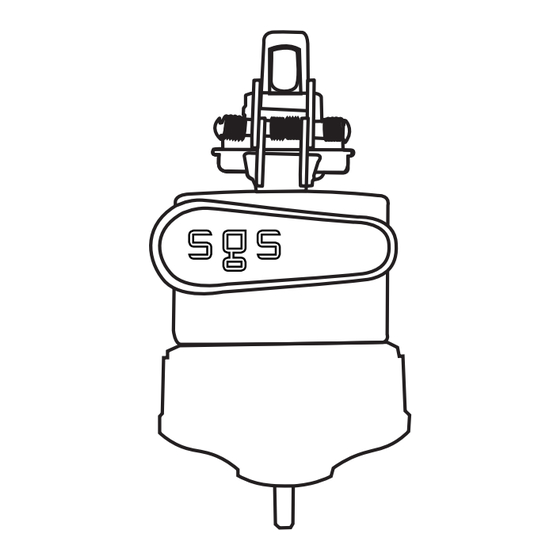
MANUAL TEST
Position the reset tool over the fault indicator's dome, aligning the
magnet with the label opposite the battery caps. Hold it for about 1
second. Remove the tool once the LEDs begin a test flash sequence;
they will stop flashing when the test is complete.
Initiating a Manual Test starts a cellular check-in and GPS lock. The LEDs
will flash up to 10 minutes as the fault indicator connects and transmits
data. Wait until the LEDs stop or check-in is confirmed at
www.portal-sgs.com before starting another test.
MANUAL RESET
While the LEDs are flashing, place the reset tool's magnet over the label
on the side of the fault indicator opposite the battery caps. Hold it there
for about 1 second; the LEDs will then stop flashing.
BATTERY REPLACEMENT
The FI-5A-W requires one 3.6V AA battery and one 3.6V C battery, each
with a wired connector. Purchase replacement batteries from SGS or an
authorized distributor. For replacement, always change both batteries.
Use a screwdriver to remove the battery caps, disconnect the batteries
at the white 2-pin connector—AA battery first, then C battery. Reconnect
the new C battery first and the AA battery second. Replace and tighten
the caps to ensure a water-tight seal: 30-32 in-lbs for the AA cap and
32-34 in-lbs for the C cap.
FOR ADDITIONAL INSTRUCTIONS,
SCAN QR CODE OR VISIT:
SMARTGRIDSOLUTIONS.COM/INSTRUCTIONS/FI5AW
PATROLMAN PLUS
FIELD USE INSTRUCTIONS
42025090HN
Advertisement

Related Manuals for SGS PATROLMAN PLUS FI-5A-W


Summary of Contents for SGS PATROLMAN PLUS FI-5A-W
- Page 1 BATTERY REPLACEMENT The FI-5A-W requires one 3.6V AA battery and one 3.6V C battery, each with a wired connector. Purchase replacement batteries from SGS or an authorized distributor. For replacement, always change both batteries. Use a screwdriver to remove the battery caps, disconnect the batteries at the white 2-pin connector—AA battery first, then C battery.
- Page 2 INSTALLATION OF FAULT INDICATOR Pull open the Clamping Mechanism with your thumbs until it locks into place. Once cocked, the unit will remain locked in the “open” position. Spring Release Trigger Clamping Mechanism Hot Stic Ring Attach the device to a shotgun stick. Position the conductor between the open Clamping Mechanism and forcefully push the device upward onto the line.
Need help?
Do you have a question about the PATROLMAN PLUS FI-5A-W and is the answer not in the manual?
Questions and answers