Table of Contents
Advertisement
Quick Links
Advertisement
Chapters
Table of Contents

Related Manuals for Classic MWECOC09S


Summary of Contents for Classic MWECOC09S
- Page 1 FOREST ON OFF SERIES SERVICE MANUAL...
- Page 2 Table of Contents §. Safety Precautions Precautions Information servicing(For flammable materials) §. Specifications Model Reference Pipe length and the Drop Height Electrical Wiring Diagrams §. Product Features Display Function Safety Features Basic Features Optional Features §. Maintenance First Time Installation Check Refrigerant Recharge Re-Installation §.
-
Page 3: Troubleshooting
Table of Contents §. Troubleshooting Safety Caution General Troubleshooting Complain Record Form Information Inquiry Error Diagnosis and Troubleshooting Without Error Code Quick Maintenance by Error Code Troubleshooting by Error Code Check Procedures Appendix Temperature Sensor Resistance Value Table for T1,T2,T3 and T4 (°C – K) Temperature Sensor Resistance Value Table for TP(for some units) (°C –... -
Page 4: Safety Precautions
Safety Precautions Contents Precautions ......................2 Information servicing(For flammable materials) ..........3... -
Page 5: In Case Of Accidents Or Emergency
1. Precautions CAUTION To prevent personal injury, or property or unit damage, While unpacking be careful of sharp edges around adhere to all precautionary measures and instructions the unit as well as the edges of the fins on the con- denser and evaporator. -
Page 6: Work Procedure
2. Information servicing(For • Prior to work taking place, the area around the equipment is to be surveyed to make sure that there are no flammable flammable materials) hazards or ignition risks. • NO SMOKING signs shall be displayed. Checks to the area Ventilated area •... -
Page 7: Detection Of Flammable Refrigerants
• that capacitors are discharged: this shall be done in shall also take into account the effects of aging or a safe manner to avoid possibility of sparking; continual vibration from sources such as compressors or fans. • that there no live electrical components and wiring are exposed while charging, recovering or purging 2.13 Detection of flammable refrigerants the system;... -
Page 8: Charging Procedures
• The refrigerant charge shall be recovered into the • Before attempting the procedure ensure that: correct recovery cylinders. The system shall be flushed • mechanical handling equipment is available, if with OFN to render the unit safe. This process may required, for handling refrigerant cylinders;... - Page 9 • Empty recovery cylinders are evacuated and, if • The recovered refrigerant shall be returned to the possible, cooled before recovery occurs. refrigerant supplier in the correct recovery cylinder, and the relevant Waste Transfer Note arranged. Do not • The recovery equipment shall be in good working mix refrigerants in recovery units and especially not in order with a set of instructions concerning the cylinders.
-
Page 10: Specifications
Specifications Contents Model Reference ....................2 Pipe Length and Drop Height ................3 Electrical Wiring Diagrams ..................4... -
Page 11: Model Reference
1. Model Reference Refer to the following table to determine the specific indoor and outdoor unit model. Indoor Unit Model Outdoor Unit Model Capacity (Btu) Power Supply 220V,60Hz, 1Phase ,60Hz, 1Phase 220-230V~, 60Hz, 1Phase Specifications 2... - Page 12 2. Pipe Length and Drop Height The length and elevation of connection pipe are shown in the table below. if the pipe length exceeds max pipe length, additional refrigerant should be charged to ensure nominal cooling/heating capacity. Capacity(Btu) Standard Length Max Pipe Length Max Elevation Additional Refrigerant...
-
Page 13: Electrical Wiring Diagrams
3. Electrical Wiring Diagrams Indoor and outdoor unit wiring diagram Indoor Unit Outdoor Unit IDU Model IDU Wiring Diagram ODU Model ODU Wiring Diagram 16022000033610 16022000020455 16022000033609 16022000020229 Specifications 4... - Page 14 Indoor unit abbreviations Abbreviation Paraphrase Yellow-Green Conductor Positive and Negative Ion Generator Capacitor PLASMA Electronic Dust Collector LIVE NEUTRAL Heater The Electric Heating Belt of Indoor Unit Indoor Room Temperature Coil Temperature of Indoor Heat Exchanger Outdoor unit abbreviations Abbreviation Paraphrase 4-WAY Gas Valve Assembly/4-WAY VALVE...
-
Page 19: Table Of Contents
Product Features Contents Display Function ....................2 Safety Features ......................3 Basic Functions .......................4 Table ......................4 Abbreviation ....................5 Fan Mode ......................5 Cooling Mode ....................5 Heating Mode(Heat Pump Units) ..............5 Auto-mode ....................6 Drying Mode ....................7 Forced Operation Function ................7 Sleep Function ....................7 3.10 Auto-Restart Function ..................7 3.11 Refrigerant Leakage Detection ...............7 3.12 Ionizer/Plasma (for some models) ..............7 Optional Functions ....................8... -
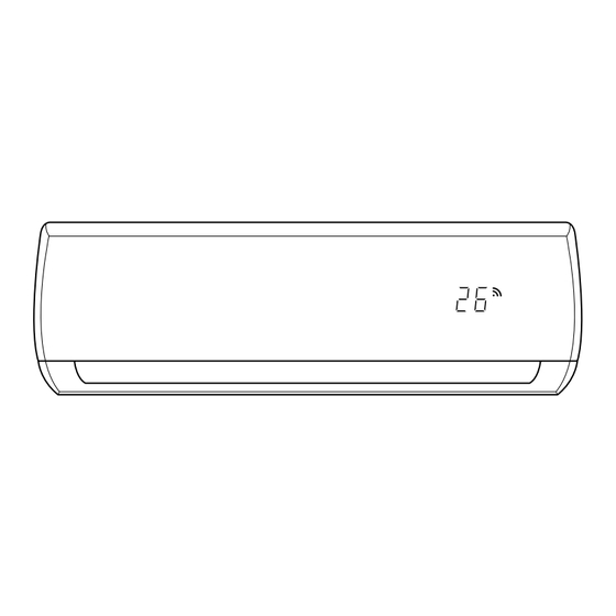
Page 20: Display Function
1. Display Function Unit display functions fresh defrost run timer fresh defrost run timer fresh defrost run timer Display A Display B Display C Display D Display E Display F Display Function Fresh(available on select units only) fresh or Defrost defrost or When the unit is on run or... -
Page 21: Safety Features
2. Safety Features Compressor three-minute delay at restart Compressor functions are delayed for up to one minute upon the first startup of the unit, and are delayed for up to three minutes upon subsequent unit restarts. Zero crossing detection error protection(Except for DC fan units) If AC can not detect zero crossing signal for 4 minutes or the zero crossing signal time interval is not correct, the unit will stop and the LED will display the failure. -
Page 22: Basic Functions
3. Basic Functions Table Heating Mode Functions Auto Mode Defrosting Mode A=2°C(3.6°F), Cases Case1:T1 and T2 Case 2:T3 B=-3°C(-5.4°F) 9k~24k cooling only Models 9k~12k heat pump Note: The detailed description of case 1 or case 2 is shown in the following function sections(from 3.5 to 3.6). Product Features 4... -
Page 23: Abbreviation
Abbreviation 3.4.3 Outdoor Fan Control Outdoor units just have one single fan speed. The Unit element abbreviations operation of outdoor fan is consistent with the operation of compressor. Except the following situations: Abbreviation Element • Condenser high temperature protection Indoor room temperature •... -
Page 24: Defrosting Mode
For above 18K models: heating mode: • Compressor current is over than I and lasts for defrost • The defrosting time has reached the setting value. Setting fan • T2 2°C(3.6°F) after entering defrosting mode for 3 speed(Turbo) minutes. TE2-6 •... -
Page 25: Drying Mode
• time on to auto mode; not higher than 30°C(86°F)) every hour. After 2 hours, the temperature stops rising and the indoor • the compressor doesn’t start in 20 minutes when a fan is fixed at low speed. running mode is set in auto. •... -
Page 26: Optional Functions
4. Optional Functions Follow me • If you press “Follow Me” on the remote, the indoor 8°C Heating unit will beep. This indicates the follow me function is active. In heating mode, the temperature can be set to as low as 8°C, preventing the indoor area from freezing if •... -
Page 27: Maintenance
Maintenance Contents First Time Installation Check .................2 Refrigerant Recharge ....................4 Re-Installation .......................5 Indoor Unit ....................5 Outdoor Unit ....................7... -
Page 28: First Time Installation Check
1. First Time Installation Check Air and moisture trapped in the refrigerant system affects To prevent air and moisture from affecting the air the performance of the air conditioner by: conditioner’s performance, the indoor unit, as well as the pipes between the indoor and outdoor unit, must be be •... - Page 29 Procedure: • If the pressure successfully reaches -0.1 MPa Tighten the flare nuts of the indoor and outdoor (14.5 Psi), fully close the Handle Lo valve, then units, and confirm that both the 2- and 3-way valves cease vacuum pump operations. are closed.
-
Page 30: Refrigerant Recharge
2. Refrigerant Recharge mA A Procedure: Close both 2- and 3-way valves. 3-way valves. Slightly connect the Handle Lo charge hose to the Operate the air conditioner in cooling mode to charge 3-way service port. the system with liquid refrigerant. Connect the charge hose to the valve at the bottom When the electronic scale displays the correct of the cylinder. -
Page 31: Re-Installation
3. Re-Installation Indoor Unit Collecting the refrigerant into the outdoor unit Procedure: Confirm that the 2- and 3-way valves are opened. Close the 3-way valve so that the gauge rests between 0.3 MPa (43.5 Psi) and 0.5 MPa (72.5 Psi). Connect the charge hose with the push pin of Handle Lo to the 3-way valve’s gas service port. - Page 32 Air purging with vacuum pump Procedure: • If the pressure successfully reaches -0.1 MPa Tighten the flare nuts of the indoor and outdoor (14.5 Psi), fully close the Handle Lo valve, then units, and confirm that both the 2- and 3-way valves cease vacuum pump operations.
-
Page 33: Outdoor Unit
Outdoor Unit Evacuation for the whole system Procedure: Wait for 5 minutes then check whether the gauge Confirm that the 2- and 3-way valves are opened. needle moves after turning off the vacuum pump. If Connect the vacuum pump to the 3-way valve’s the gauge needle moves backward, check whether service port. - Page 34 Refrigerant charging mA A Procedure: Close both 2- and 3-way valves. Fully open the Handle Lo manifold valve, 2- and 3-way valves. Slightly connect the Handle Lo charge hose to the 3-way service port. Operate the air conditioner in cooling mode to charge the system with liquid refrigerant.
- Page 35 Indoor Unit Disassembly Contents Dimension ......................2 Indoor Unit Disassembly ..................3 Front Panel ....................3 Electrical parts ....................8 Evaporator ....................12 Fan motor and fan ..................14 Step motor ....................16 Drain Hose ....................17...
-
Page 36: Dimension
1. Dimension Capacity Body Code W(mm) D(mm) H(mm) 5K~11K 9K~14K 17K~18K 18K~24K 1040 Indoor Unit Disassembly 2... -
Page 37: Front Panel
2. Disassembly Indoor unit Front Panel Procedure Illustration 1) Hold the front panel by the tabs on Front Panel the both sides and lift it (see CJ_ AF_001). CJ_AF_001 2) Push up the bottom of an air filter, and then pull it out downwards (see CJ_AF_002). - Page 38 Procedure Illustration 3) Open the horizontal louver and push the hook towards left to open it (see CJ_AF_003). Horizontal Louver Hook CJ_AF_003 4) Bend the horizontal louver lightly by both hands to loosen the hooks, then remove the horizontal louver (see CJ_AF_004).
- Page 39 Procedure Illustration 5) Remove 1 screw and then remove the electrical cover(see CJ_AF_005-1 and CJ_AF_005-2). CJ_AF_005-1 CJ_AF_005-2 6) Disconnect the connector for display board(see CJ_AF_005-3) . CJ_AF_005-3 7) Remove the display board(see CJ_ AF_005-4). CJ_AF_005-4 CJ_AF_005 Note: This section is for reference only. Actual unit appearance may vary. Indoor Unit Disassembly 5...
- Page 40 Procedure Illustration 8) Open the screw caps(2) and the remove the screws(see CJ_AF_006). 9) Release the 4 hooks. CJ_AF_006 10) Release the seven hooks in the back (see CJ_AF_007). Hooks CJ_AF_007 Note: This section is for reference only. Actual unit appearance may vary. Indoor Unit Disassembly 6...
- Page 41 Procedure Illustration 11) Pull out the panel frame while pushing the hook through a clearance between the panel frame and the heat exchanger (see CJ_AF_008). CJ_AF_008 Panel Frame Note: This section is for reference only. Actual unit appearance may vary. Indoor Unit Disassembly 7...
-
Page 42: Electrical Parts
Electrical parts Note: Remove the front panel (refer to 1. Front panel) before disassembling electrical parts. Procedure Illustration 1) Remove the fixing screw and then remove the cover of electronic box and the terminal cover (see CJ_AF_009). Electronic Cover Fixing Screw CJ_AF_009 2) Pull out the room temperature sensor (T1) and the coil temperature sensor... - Page 43 Procedure Illustration 4) Remove the fixing screw (see CJ_ AF_011-1). 5) Pull out the Electrical control box along the direction indicated in right image. to remove it (CJ_AF_011-2). Fixing Screw CJ_AF_011-1 Electronic Box CJ_AF_011-2 Swing Motor Applicable to AC Motor Only Indoor Fan Motor 6) Disconnect the wires.
- Page 44 Procedure Illustration 7) Remove the fixing screw, then remove the capacitor of fan motor (see CJ_ AF_013). Capacitor of Fan Motor CJ_AF_013 Note: This section is for reference only. Actual unit appearance may vary. Indoor Unit Disassembly 10...
-
Page 45: Evaporator
Evaporator Note: Remove the front panel and electrical parts (refer to 1. Front panel and 2. Electrical parts) before disassembling evaporator. Procedure Illustration 1) Disassemble the pipe holder located at the rear of the unit (see CJ_AF_014). Pipe Holder CJ_AF_014 2) Remove the screws on the evaporator located at the fixed plate (see CJ_AF_015). - Page 46 Procedure Illustration 4) Pull out the evaporator (see CJ_AF_017). Evaporator CJ_AF_017 Note: This section is for reference only. Actual unit appearance may vary. Indoor Unit Disassembly 12...
-
Page 47: Fan Motor And Fan
Fan motor and fan Note: Remove the front panel, electrical parts and evaporator (refer to 1. Front panel, 2. Electrical parts, and 3. Evaporator). before disassembling fan motor and fan. Procedure Illustration 1) Remove the two screws and remove the fixing board of the fan motor (see CJ_ AF_018). -
Page 48: Step Motor
Step motor Note: Remove the front panel and electrical parts (refer to 1. Front panel, 2. Electrical parts) before disassembling step motor. Procedure Illustration 1) Remove the two screws, then remove the stepping motor (see CJ_AF_021). Stepping Motor CJ_AF_021 Note: This section is for reference only. Actual unit appearance may vary. Indoor Unit Disassembly 14... - Page 49 Outdoor Unit Disassembly Contents Outdoor Unit Table ....................2 Dimension ......................3 Outdoor Unit Disassembly ..................21 Panel Plate ....................21 Electrical Parts .....................46 Fan Assembly ....................65 Fan Motor ....................66 Sound blanket .....................67 Four-way valve .....................68 Compressor ....................69...
-
Page 50: Outdoor Unit Disassembly
1. Outdoor Unit Disassembly Outdoor Unit Table Outdoor Unit Model Panel Plate PCB Board MOX130-09HN1-NB8 X130 PCB Board 1 MOX130-11HN1-NB6 X130 PCB Board 1 MOX130-12CN1-NB8 X130 PCB Board 1 MOX230-18CN1-NB8 X230 PCB Board 1 MOX330-24CN1-NB8 X330 PCB Board 1 Outdoor Unit Disassembly 2... - Page 51 2. Dimension AA30 Panel Plate Outdoor Unit Disassembly 3...
- Page 52 AB30 Panel Plate Outdoor Unit Disassembly 4...
- Page 53 BA30 Panel Plate Outdoor Unit Disassembly 5...
- Page 54 For US models: Outdoor Unit Disassembly 6...
- Page 55 Panel Plate Outdoor Unit Disassembly 7...
- Page 56 For US models: Outdoor Unit Disassembly 8...
- Page 57 CA30 Panel Plate Outdoor Unit Disassembly 9...
- Page 58 For US models: Outdoor Unit Disassembly 10...
- Page 59 Panel Plate Outdoor Unit Disassembly 11...
- Page 60 For US models: Outdoor Unit Disassembly 12...
- Page 61 X130 Panel Plate Outdoor Unit Disassembly 13...
- Page 62 For US models: Outdoor Unit Disassembly 14...
- Page 63 X230 Panel Plate Outdoor Unit Disassembly 15...
- Page 64 For US models: Outdoor Unit Disassembly 16...
- Page 65 X330 Panel Plate Outdoor Unit Disassembly 17...
- Page 66 For US models: Outdoor Unit Disassembly 18...
- Page 67 X430 Panel Plate Outdoor Unit Disassembly 19...
- Page 68 For US models: Outdoor Unit Disassembly 20...
-
Page 69: Panel Plate
3. Outdoor Unit Disassembly Panel Plate 1. AA30 / AB30 Procedure Illustration 1) Turn off the air conditioner and the power breaker. Big Handle 2) Remove the screws of the big handle and then remove the big handle (1 screws) (see CJ_AA30_001). CJ_AA30_001 Top Cover 3) Remove the screws of the top cover... - Page 70 Procedure Illustration 4) Remove the screws of the front panel and then remove the front panel (6 screws) (see CJ_AA30_003). Front Panel CJ_AA30_003 5) Remove the screws of water collecting cover (2 screws) (see CJ_AA30_004). Water Collecting Cover CJ_AA30_004 Note: This section is for reference only. Actual unit appearance may vary. Outdoor Unit Disassembly 22...
- Page 71 Procedure Illustration 6) Remove the screws of the rear net and then remove the rear net (2 screws) CJ_AA30_005). (for some (see models) CJ_AA30_005 7) Remove the screws of the right panel and then remove the right panel (6 screws) (see CJ_AA30_006). Right Panel CJ_AA30_006 Note: This section is for reference only.
- Page 72 2. BA30 Procedure Illustration 1) Turn off the air conditioner and the Big Handle power breaker. 2) Remove the screws of the big handle and then remove the big handle (1 screws) (see CJ_BA30_001). CJ_BA30_001 Top Cover 3) Remove the screws of the top cover and then remove the top cover (3 screws).
- Page 73 Procedure Illustration 4) Remove the screws of the front panel and then remove the front panel (7 screws) (see CJ_BA30_003). Front Panel CJ_BA30_003 5) Remove the screws of water collecting Water Collecting Cover cover (2 screws) (see CJ_BA30_004). CJ_BA30_004 Note: This section is for reference only. Actual unit appearance may vary. Outdoor Unit Disassembly 25...
- Page 74 Procedure Illustration 6) Remove the screws of the rear net and then remove the rear net (2 (for some screws) (see CJ_BA30_005). models) CJ_BA30_005 7) Remove the screws of the right panel and then remove the right panel (6 screws) (see CJ_BA30_006). Right Panel CJ_BA30_006 Note: This section is for reference only.
- Page 75 3. B30 Procedure Illustration 1) Turn off the air conditioner and the power breaker. Big Handle 2) Remove the screws of the big handle and then remove the big handle (1 screws) (see CJ_B30_001). CJ_B30_001 Top Cover 3) Remove the screws of the top cover and then remove the top cover (3 screws).
- Page 76 Procedure Illustration 4) Remove the screws of the front panel and then remove the front panel (8 screws) (see CJ_B30_003). Front Panel CJ_B30_003 5) Remove the screws of water collecting cover and then remove the water collecting cover (2 screws) (see CJ_ Water Collecting Cover B30_004).
- Page 77 Procedure Illustration 6) Remove the screws of the rear net and then remove the rear net (2 screws) CJ_B30_005). (for some models) (see CJ_B30_005 7) Remove the screws of the right panel and then remove the right panel (5 screws) (see CJ_B30_006). Right Panel CJ_B30_006 Note: This section is for reference only.
- Page 78 4. CA30 Procedure Illustration 1) Turn off the air conditioner and the power breaker. 2) Remove the screws of the big handle and then remove the big handle Big Handle (1 screws) (see CJ_CA30_001). CJ_CA30_001 Top Cover 3) Remove the screws of the top cover and then remove the top cover (3 screws).
- Page 79 Procedure Illustration 4) Remove the screws of the front panel and then remove the front panel (7 screws) (see CJ_CA30_003). Front Panel CJ_CA30_003 5) Remove the screws of water collecting cover and then remove the water Water Collecting Cover collecting cover (2 screws) (see CJ_ CA30_004).
- Page 80 Procedure Illustration 6) Remove the screws of the rear net and then remove the rear net (2 screws) CJ_CA30_005). (for some (see models) CJ_CA30_005 7) Remove the screws of the right panel and then remove the right panel (7 screws) (see CJ_CA30_006). Right Panel CJ_CA30_006 Note: This section is for reference only.
- Page 81 5. D30 Procedure Illustration 1) Turn off the air conditioner and the Big Handle power breaker. 2) Remove the screws of the big handle and then remove the big handle (2 screws) (see CJ_D30_001). CJ_D30_001 3) Remove the screws of the top cover and then remove the top cover (4 Top Cover screws).
- Page 82 Procedure Illustration 4) Remove the screws of the front right panel and then remove the front right panel (2 screws) (see CJ_D30_003). Front Right Panel CJ_D30_003 5) Remove the screws of the front panel and then remove the front panel (9 screws) (see CJ_D30_004).
- Page 83 Procedure Illustration 6) Remove the screws of water collecting cover and then remove the water collecting cover (2 screw) (see CJ_ D30_005). Water Collecting Cover CJ_D30_005 7) Remove the screws of the rear net and then remove the rear net (2 screws) CJ_D30_006).
- Page 84 Procedure Illustration 8) Remove the screws of the right panel and then remove the right panel (8 screws) (see CJ_D30_007). Right Panel CJ_D30_007 Note: This section is for reference only. Actual unit appearance may vary. Outdoor Unit Disassembly 36...
- Page 85 6. X130 Procedure Illustration 1) Turn off the air conditioner and the power breaker. 2) Remove the screw of the big handle and then remove the big handle (1 screw) (see CJ_X130_001). Big Handle CJ_X130_001 Top Cover 3) Remove the screws of the top cover and then remove the top cover (3 screws).
- Page 86 Procedure Illustration 4) Remove the screws of water collecting cover and then remove the water collecting cover (2 screws) (see CJ_ X130_003). Water Collecting Cover CJ_X130_003 5) Remove the screws of the front panel and then remove the front panel (6 screws(onoff models) or 8 screws(inverter models) (see CJ_ X130_004).
- Page 87 Procedure Illustration 6) Remove the screws of the right panel and then remove the right panel (5 screws) (see CJ_X130_005). Right Panel CJ_X130_005 Note: This section is for reference only. Actual unit appearance may vary. Outdoor Unit Disassembly 39...
- Page 88 7. X230/X330 Procedure Illustration 1) Turn off the air conditioner and the power breaker. 2) Remove the screw of the big handle and then remove the big handle (1 screws) (see CJ_X230_001). Big Handle CJ_X230_001 Top Cover 3) Remove the screws of the top cover and then remove the top cover (4 screws).
- Page 89 Procedure Illustration 4) Remove the screws of water collecting cover and then remove the water collecting cover (2 screws) (see CJ_ X230_003). Water Collecting Cover CJ_X230_003 5) Remove the screws of the front panel and then remove the front panel (7 screws(onoff models) or 9 screws(inverter models) (see CJ_ X230_004).
- Page 90 Procedure Illustration 6) Remove the screws of the right panel and then remove the right panel (5 screws) (see CJ_X230_005). Right Panel CJ_X230_005 Note: This section is for reference only. Actual unit appearance may vary. Outdoor Unit Disassembly 42...
- Page 91 8. X430 Procedure Illustration 1) Turn off the air conditioner and the power breaker. 2) Remove the screw of the big handle and then remove the big handle (1 screw) (see CJ_X430_001). Big Handle CJ_X430_001 Top Cover 3) Remove the screws of the top cover and then remove the top cover (3 screws).
- Page 92 Procedure Illustration 4) Remove the screws of water collecting cover and then remove the water collecting cover (2 screws) (see CJ_ X430_003). Water Collecting Cover CJ_X430_003 5) Remove the screws of the front panel and then remove the front panel (7 screws(onoff models) or 9 screws(inverter models) (see CJ_ X430_004).
- Page 93 Procedure Illustration 6) Remove the screws of the right panel and then remove the right panel (6 screws) (see CJ_X430_005). Right Panel CJ_X430_005 Note: This section is for reference only. Actual unit appearance may vary. Outdoor Unit Disassembly 45...
-
Page 94: Electrical Parts
Electrical parts Antistatic gloves must be worn when you disassemble the electronic box. WARNING: Note: Remove the air outlet grille(refer to 3.1 Panel Plate) before disassembling electrical parts. PCB for ON-OFF Models 1. PCB board 1 Procedure Illustration 1) Remove the two screws fixed the electronic control board (see CJ_ ODU_PCB_001). - Page 95 Procedure Illustration 8) For models with subzero refrigeration control board, remove 3 screws of it showed in the figure. CJ_ODU_PCB_001-03 9) The subzero refrigeration control board is in the back of the medal sheet. CJ_ODU_PCB_001-04 Note: This section is for reference only. Actual unit appearance may vary. Outdoor Unit Disassembly 47...
- Page 96 2. PCB board 2 Procedure Illustration Capacitor of compressor 1) Remove the fixing screws of the compressor capacitor, then pull it out (see CJ_ODU_PCB_002-1) 2) Remove 2 screws of the transformer and then remove it. (see CJ_ODU_ PCB_002-1) 3) Remove the fixing screws of the fan motor capacitor, then remove it.
- Page 97 Procedure Illustration Fan Motor 6) Disconnect the wires connected to the compressor. (Red wire connects 4-Way Valve Compressor with PCB board, others connects with terminals) (see CJ_ODU_PCB_002-3) (For some models) 7) Disconnect the connectors for fan motor. (Blue wire, red wire, brown wire and black wire.
- Page 98 PCB for Inverter Models 4. PCB board 4 Procedure Illustration 1) Remove the screws of the top cover. CJ_ODU_PCB_004- (2 screws) (see 1 ). CJ_ODU_PCB_004-1 2) Unfix the hooks and then open the electronic control box cover (4 hooks) CJ_ODU_PCB_004-2 ). (see 3) Disconnect the connector for fan motor from the electronic control...
- Page 99 5. PCB board 5 Procedure Illustration 1) Unfix the hooks and then open the electronic control box cover (4 hooks) CJ_ODU_PCB_005-1 ). (see 4-Way Valve 2) Disconnect the connector for fan CJ_ODU_PCB_005-1 motor from the electronic control CJ_ODU_PCB_005-2 ). board (see 3) Remove the connector for the Reactor CJ_ODU_PCB_005-...
- Page 100 5. PCB board 6 Procedure Illustration 1) Remove the screws and unfix the hooks, then open the electronic control box cover (5 screws and 2 CJ_ODU_PCB_006-1 ). hooks )(see CJ_ODU_PCB_006-1 2) Disconnect the connector for fan motor from the electronic control CJ_ODU_PCB_006-2 ).
- Page 101 6. PCB board 7 Procedure Illustration 1) Remove the screws of the top cover. (1 screws) (see CJ_ODU_PCB_007- 1 ). CJ_ODU_PCB_007-1 2) Unfix the hooks and then open the electronic control box cover (5 hooks) CJ_ODU_PCB_007-2 ). (see CJ_ODU_PCB_007-2 3) Disconnect the connector for fan motor from the IPM board (see ODU_PCB_007-3 ).
- Page 102 Procedure Illustration 5) Pull out the wire connected with the CJ_ODU_PCB_007-4 ). terminal. (see T3/T4 6) Pull out connectors of the condenser coil temp. sensor(T3),outdoor ambient temp. sensor(T4) and discharge temp. CJ_ODU_PCB_007-4 ). sensor(TP) (see 7) Disconnect the electronic expansion CJ_ODU_PCB_007- valve wire (see Fig 4 ).
- Page 103 7. PCB board 8 Procedure Illustration 1) Unfix the hooks and then open the electronic control box cover (4 hooks) CJ_ODU_PCB_008-1 ). (see 2) Disconnect the connector for outdoor DC fan from the electronic CJ_ODU_ control board (see PCB_008-2 ). 3) Remove the connector for the CJ_ODU_PCB_008- compressor (see...
- Page 104 9. PCB board 9 Procedure Illustration 1) Disconnect the connector for compressor and release the ground CJ_ODU_ wire(1 screw). (see PCB_009-1 ). 2) Pull out the wires from electrical supporting plate and turn over the CJ_ODU_PCB_009-1 electronic control assembly. (see CJ_ODU_PCB_009-2 ).
- Page 105 Procedure Illustration 4) Remove the fixing board (2 hooks) CJ_ODU_PCB_009-4 ). (see CJ_ODU_PCB_009-4 5) Disconnect the connectors from the electronic control board (see CJ_ODU_PCB_009-5 ). CJ_ODU_PCB_009-5 6) Then remove the electronic control board (4 hooks).(see CJ_ODU_ PCB_009-6 ). CJ_ODU_PCB_009-6 Note: This section is for reference only. Actual unit appearance may vary. Outdoor Unit Disassembly 57...
- Page 106 10. PCB board 10 Procedure Illustration 1) Unfix the hooks and then open the electronic control box cover (4 hooks) CJ_ODU_PCB_010-1 ). (see CJ_ODU_PCB_010-1 2) Remove 4 screws on the electronic control board and then turn over the electronic control board (see CJ_ODU_PCB_010-2 ).
- Page 107 Procedure Illustration 3) Pull out the connectors (see ODU_PCB_010-3 ). 4) Remove the 9 screws and unfix the 3 hooks and then remove the electronic control board(see ODU_PCB_010-3 ). CJ_ODU_PCB_010-3 5) Remove two screws and then remove the electronic control box subassembly on partition board assembly.
- Page 108 Procedure Illustration 6) Remove two screws and two connectors and then remove the CJ_ODU_ inverter control board (see PCB_010-5 ). CJ_ODU_PCB_010-5 Note: This section is for reference only. Actual unit appearance may vary. Outdoor Unit Disassembly 60...
- Page 109 11. PCB board 11 Procedure Illustration 1) Disconnect the connector for compressor and release the ground CJ_ODU_ wire(1 screw). (see PCB_0011-1 ). 2) Pull out the wires from electrical supporting plate and turn over the CJ_ODU_PCB_011-1 electronic control assembly. (see CJ_ODU_PCB_011-2 ).
- Page 110 Procedure Illustration 4) Remove the fixing board (2 hooks) CJ_ODU_PCB_011-4 ). (see CJ_ODU_PCB_011-4 5) Disconnect the connectors from the electronic control board (see CJ_ODU_PCB_011-5 ). CJ_ODU_PCB_011-5 6) Then remove the electronic control board (4 hooks).(see CJ_ODU_ PCB_011-6 ). CJ_ODU_PCB_011-6 Note: This section is for reference only. Actual unit appearance may vary. Outdoor Unit Disassembly 62...
- Page 111 12. PCB board 12 Procedure Illustration 1) Unfix the hooks and then open the electronic control box cover (4 hooks) CJ_ODU_PCB_012-1 ). (see CJ_ODU_PCB_012-1 2) Remove 6 screws on the electronic control board and then turn over the electronic control board (see CJ_ODU_PCB_012-2 ).
- Page 112 Procedure Illustration 3) Pull out the connectors (see ODU_PCB_012-3 ). 4) Remove the 4 screws and then remove the electronic control CJ_ODU_PCB_012-3 ). board(see CJ_ODU_PCB_012-3 Note: This section is for reference only. Actual unit appearance may vary. Outdoor Unit Disassembly 64...
-
Page 113: Fan Assembly
Fan Assembly Note: Remove the panel plate (refer to 3.1 Panel Plate) before disassembling fan. Procedure Illustration 1) Remove the nut securing the fan with a spanner (see CJ_ODU_ FAN_001). 2) Remove the fan. D-cut CJ_ODU_FAN_001 Note: This section is for reference only. Actual unit appearance may vary. Outdoor Unit Disassembly 65... -
Page 114: Fan Motor
Fan Motor Note: Remove the panel plate and the connection of fan motor on PCB (refer to 3.1 Panel Plate and 3.2 Electrical parts) before disassembling fan motor. Procedure Illustration 3) Remove the fixing screws of the fan motor (4 screws) (see CJ_ODU_MOTOR_001). 4) Remove the fan motor. -
Page 115: Sound Blanket
Sound blanket Note: Remove the panel plate (refer to 3.1 Panel plate) before disassembling sound blanket. Procedure Illustration 1) Remove the sound blanket (side and top) (see CJ_ODU_BLANKET_001). Sound Blanket(top) Sound Blanket(side) CJ_ODU_BLANKET_001 Note: This section is for reference only. Actual unit appearance may vary. Outdoor Unit Disassembly 67... - Page 116 Four-way valve (for heat pump models) WARNING: Evacuate the system and confirm that there is no refrigerant left in the system before removing the four-way valve and the compressor. (For R32 & R290, you should evacuate the system with the vacuum pump; flush the system with nitrogen;...
- Page 117 Compressor WARNING: Evacuate the system and confirm that there is no refrigerant left in the system before removing the four-way valve and the compressor. (For R32 & R290, you should evacuate the system with the vacuum pump; flush the system with nitrogen; then repeat the two steps before heating up the brazed parts. The operations above should be implemented by professionals.) Note: Remove the panel plate, connection of compressor on PCB (refer to 3.1 Panel plate and 3.2 Electrical parts) before disassembling sound blanket.
- Page 118 Procedure Illustration 3) Remove the hex nuts and washers securing the compressor, located on the bottom plate (see CJ_ODU_COMP_003). CJ_ODU_COMP_003 Suction Pipe 4) Heat up the brazed parts and then remove the the discharge pipe and the suction pipe (see CJ_ODU_COMP_004). Discharge Pipe 5) Lift the compressor from the base pan assembly with pliers.
Need help?
Do you have a question about the MWECOC09S and is the answer not in the manual?
Questions and answers