
Related Manuals for HPC FPPK Series


Summary of Contents for HPC FPPK Series
- Page 1 PUSH-BUTTON / FLAME SENSING CONTROL BOX FPPK Series Installation & Operation Instructions 840-FPPK...
- Page 3 These are Warning and Danger Symbols When you see this symbol on the fire pit insert, or in this manual, look for one of the following signal word panels alerting you to the potential for personal injury, death, or major property damage.
- Page 4 DANGER • FLAMMABLE GAS UNDER PRESSURE. LEAKING LP-GAS MAY CAUSE A FIRE OR EXPLOSION IF IGNITED CAUSING SERIOUS BODILY INJURY OR DEATH. CONTACT LP GAS SUPPLIER FOR REPAIRS, OR DISPOSAL OF THIS CYLINDER OR UNUSED LP-GAS. WARNING: • FOR OUTDOOR USE ONLY. * DO NOT USE OR STORE CYLINDER IN A BUILDING, GARAGE OR ENCLOSED AREA.
-
Page 5: Table Of Contents
Table of Contents Important Safety Information ....................... 3 Technical Support ........................3 Symbol Legend ......................... 4 Important Safety Information for Installers ................5 Important Safety Information for End-Users ................5 Product Features and Parts List ....................6 Selecting the Fire Pit Location ..................... 7 Overhead Structures and Sidewall Clearance Requirements ........... -
Page 7: Important Safety Information
Important Safety Information • Hearth Products Controls Company recommends that our products are installed INSTALLER: by professionals locally licensed by the authority having jurisdiction in gas piping. Leave this manual with All installation instructions must be followed to ensure proper performance and the appliance. -
Page 8: Symbol Legend
Important Safety Information Symbol Legend These are Warning and Danger Symbols When you see this symbol on the fire pit insert, or in this manual, look for one of the following signal word panels alerting you to the potential for personal injury, death, or major property damage. -
Page 9: Important Safety Information For Installers
Important Safety Information Please reference page 1 for all warnings. Important Safety Information for Installers Leave this manual with the end-user and instruct them to retain it for future reference. Instructions and product updates are also available at www.hpcfire.com under the Support tab. Installers must carefully follow the instructions in this manual to prevent personal injury or property loss. -
Page 10: Product Features And Parts List
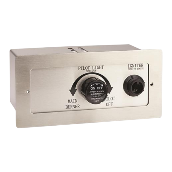
Product Features and Parts List Ignition System Blowout Box FPPK Control Push-button Igniter Valve Control... -
Page 11: Selecting The Fire Pit Location
It is recommended that material such as granite, marble IMPORTANT or other dense stone be kept away from heat and especially flame due to risk of cracking. HPC is not responsible for damage resulting from failure to follow these recommendations. -
Page 12: Overhead Structures And Sidewall Clearance Requirements
Overhead Structures and Sidewall Clearance Requirements WARNING: It is important to review the clearance requirements below for any type of overhead structure such as pergola, roof, overhang, screens, arbor, etc. or a sidewall to ensure that the distances are met. Figures 4.1 and 4.2. Figure 1 - Up to 142k BTU For Outdoor Use Only Figure 4.1 –... - Page 13 Overhead Structures and Sidewall Clearance Requirements Figure 4.2 – Up to 100,000 BTU: LP Tank REVISIONS Figure 1 - up to 100,000 BTU: LP Tank For Outdoor Use Only – Select Models Only ZONE DESCRIPTION DATE APPROVED For Outdoor Use Only - Select models only Overhead structure to include: (roof, overhang, pergola, or screen) for products up to 100,000 BTU.
-
Page 14: Fire Pit Enclosures Requirements
• The weight of the fire pit must be supported by the pan and not by any control/ valve box. • HPC recommends that the pan lip is recessed on a trough (linear), and large round enclosures, Figure 5.1. NOTE: HPC cannot guarantee the lip on all our products will be perfectly flat and will not warp due to heat. -
Page 15: Construction Materials
- Multiple vents uniformly made throughout the enclosure totaling the required free area or more free area per the BTU range are acceptable. - Ventilation along the bottom of the enclosure allows for a full open design is acceptable as well. HPC unfinished enclosures reflect this ventilation. -
Page 16: Remote Lp Tank System Enclosure Requirements - If Applicable
IMPORTANT are permissible for small tank use. Please see the HPC product catalog, visit www.hpcfire.com, or contact your HPC dealer for details. Locate the hose out of pathways to avoid accidental IMPORTANT damage and prevent it from becoming a trip hazard. - Page 17 Remote LP Tank System Enclosure Requirements - If Applicable • Ventilation openings in sidewalls shall not communicate directly with other enclosures of the appliance. See Tables 6.1 and 6.2. LP Tank Size Top Opening Bottom Opening 20 LB (9.1 KG) 20 in (130 cm 10 in...
- Page 18 Remote LP Tank System Enclosure Requirements - If Applicable Propane Cylinder: Safety Requirements • This appliance has been designed for use with a 20-lb. or 30-lb. size propane cylinder (not supplied). • The propane cylinder should be checked by your propane supplier prior to installation and use.
- Page 19 Remote LP Tank System Enclosure Requirements – If Applicable Locating the LP tank: Figure 6.2 Securing the LP tank: WARNING: Failure to follow location 1. Fasten the L-bracket to the bottom of the propane tank and mounting guidelines for the LP using the nut and bolt (supplied).
-
Page 20: Installing The Fire Pit
Installing the Fire Pit Ensure unit is set to proper gas type before installing fire pit into enclosure. If gas type IMPORTANT is incorrect, follow steps below before continuing to Installation Steps: UGO™ Orifice Gas Style Setting: 1. Using a 2.5mm hex driver to loosen set screw on the back side of orifice and rotate collar. Once set lightly snug the set screw to lock down the collar but do not over tighten. - Page 21 Installing the Fire Pit Fuel line: WARNING: There must be a gas shutoff on the outside of the exterior of the enclosure to allow for emergency shut off and maintenance. The gas shutoff should not be used to adjust flame height. •...
-
Page 22: Adding Approved Media
Adding Approved Media – When using approved decorative glass to cover WARNING: For glass media usage with LP gas burner apply enough to hide burner. Applying over ½” may create back pressure and gas leakage from air mixer venturi holes resulting in LP pooling under fire pit. WARNING: For glass media usage with LP gas - the unit must be tested with media over burner for confirmation of no back pressure creating gas to leak out of air mixer venturi holes. - Page 23 Adding Approved Media Application of Approved Media Please follow the instructions below to add the final addition to your fire pit. Particular attention needs to be paid to the pilot assembly area. Incorrect media installation will cause the pilot flame to suffocate and turn off pit or delay main burner ignition.
-
Page 24: Operating The Fire Pit
Operating the Fire Pit WARNING: Before use, be sure to test all gas connections for leaks. Do not use a fire pit if there is any evidence of leaking gas. If leaking gas is suspected, turn off the main gas supply and repair it immediately. - Page 25 Operating the Fire Pit FPPK Push-Button Flame Sensing DANGER Start-up If you smell gas: Shut off gas to appliance. 1. STOP! Read the safety information on Extinguish any open flame. “If you smell gas,” Section 1 – Important If the odor continues, keep away Safety Information.
-
Page 26: Maintaining The Fire Pit
Maintaining the Fire Pit • Any guard or protective device removed for servicing must Service be replaced prior to operating the fire pit. We suggest that our products • We suggest that our products be serviced annually by a be serviced by a professional professional certified in the US by the National Fireplace certified in the US by the Institute (NFI) as NFI Gas Specialists. - Page 27 Maintaining the Fire Pit Installing / Changing Batteries to Spark Igniter Unit in Valve Box Carefully unscrew the spark igniter unit cap, Figure 10.4. 1. Remove cap with battery counterclockwise 2. Remove old battery from cap, install new battery 3. Holding by cap, slide battery into spark igniter unit. 4.
-
Page 28: Troubleshooting
Troubleshooting Table 11.1 below indicates some potential causes Service and countermeasures to the symptoms indicated in bold type. Please contact your retailer or certified We suggest that our products be technician for service and repair. serviced by a professional certified in the US by the National Fireplace Institute (NFI) as NFI Gas Specialists. -
Page 29: Compatible Accessories
For a complete list of accessories, visit www.hpcfire.com Figure 12.1 – Fire pit cover Replacement Parts Please contact your dealer for parts – if unsure please contact HPC or visit our website at www.hpcfire.com and we will be happy to help you... -
Page 30: Warranty
4) Stainless Steel Pan, Valve Box: Commercial-1 year; Residential-5 years Warranty commences from the date of original sale / shipment from HPC FOB Dayton, Ohio. This warranty is for parts and in-house (HPC) labor. The defective product must be sent back to HPC with a Return Merchandise Authorization (RMA) issued by HPC for that specific product and any other additional information for the nature of the defect or warranty claim.
Need help?
Do you have a question about the FPPK Series and is the answer not in the manual?
Questions and answers