
Related Manuals for Hitachi DV-P735U(C)


Summary of Contents for Hitachi DV-P735U(C)
- Page 1 All manuals and user guides at all-guides.com No. 9301E DV-P735U DV-P735U(C) SERVICE MANUAL DV-P533U SPECIFICATIONS AND PARTS ARE SUBJECT TO CHANGE FOR IMPROVEMENT DVD PLAYER February 2003 Digital Media Division, Tokai...
-
Page 2: Table Of Contents
All manuals and user guides at all-guides.com CONTENTS 1 CAUTIONS FOR SAFETY IN PERFORMING SCHEMATIC AND BLOCK DIAGRAMS/CBA'S REPAIR ....... .1-1 1 SCHEMATIC DIAGRAMS/CBA’S AND TEST POINTS . -
Page 3: Cautions For Safety In Performing Repair
All manuals and user guides at all-guides.com CAUTION FOR SAFETY IN PERFORMING REPAIR 1-1 LASER BEAM SAFETY PRECAUTIONS This DVD player uses a pickup that emits a laser beam. Do not look directly at the laser beam coming from the pickup or allow it to strike against your skin. -
Page 4: Important Safety Precautions
All manuals and user guides at all-guides.com 1-2 IMPORTANT SAFETY PRECAUTIONS 1-2-1 Product Safety Notice I. Also check areas surrounding repaired locations. J. Be careful that foreign objects (screws, solder Some electrical and mechanical parts have special droplets, etc.) do not remain inside the set. safety-related characteristics which are often not evi- K. -
Page 5: Safety Check After Servicing
All manuals and user guides at all-guides.com 1-2-3 Safety Check after Servicing Examine the area surrounding the repaired location for damage or deterioration. Observe that screws, parts, Chassis or Secondary Conductor and wires have been returned to their original posi- tions. -
Page 6: Standard Notes For Servicing
All manuals and user guides at all-guides.com 1-3 STANDARD NOTES FOR SERVICING 1-3-1 Circuit Board Indications 1-3-3 How to Remove / Install Flat Pack-IC a. The output pin of the 3 pin Regulator ICs is indi- cated as shown. 1. Removal With Hot-Air Flat Pack-IC Desoldering Machine:. - Page 7 All manuals and user guides at all-guides.com With Soldering Iron: (4) Bottom of the flat pack-IC is fixed with glue to the CBA; when removing entire flat pack-IC, first apply (1) Using desoldering braid, remove the solder from all soldering iron to center of the flat pack-IC and heat pins of the flat pack-IC.
-
Page 8: Installation
All manuals and user guides at all-guides.com 2. Installation 1-3-4 Instructions for Handling Semi-conductors (1) Using desoldering braid, remove the solder from the foil of each pin of the flat pack-IC on the CBA Electrostatic breakdown of the semi-conductors may so you can install a replacement flat pack-IC more occur due to a potential difference caused by electro- easily. -
Page 9: General Information
All manuals and user guides at all-guides.com GENERAL INFORMATION 2-1 SPECIFICATIONS... -
Page 10: Comparison Of Models
All manuals and user guides at all-guides.com 2-2 COMPARISON OF MODELS ←: Same as on left ITEM DV-P735U/P735U(C)/P533U DV-P725U/P325U/P323U Dimensional 435(W) x 55(H) x 211(D) mm 435(W) x 75(H) x 216(D) mm Weight 1.8 kg 2.1 kg Tray Panel Clear Silver Dark Silver/Silver (DV-P725U) Silver/Silver (DV-P735U/P735U(C)) - Page 11 All manuals and user guides at all-guides.com ITEM DV-P735U/P735U(C)/P533U DV-P725U/P325U/P323U O (DV-P735U/P735U(C)) Disc Navigation --- (DV-P533U) ← DVD Zoom x2 / x4 / x16 O / O / --- Program and Random Play of DVD / ← ← A-B Repeat ←...
-
Page 12: Operating Controls And Functions
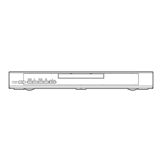
All manuals and user guides at all-guides.com 2-3 OPERATING CONTROLS AND FUNCTIONS [ DV-P735U/P735(C) ] FRONT PANEL SKIP/FR PLAY FF/SKIP STOP OPEN/CLOSE y/I POWER/ STANDBY REAR VIEW ANALOG AUDIO OUT COMPONENT VIDEO OUT DIGTAL AUDIO OUT COAXIAL VIDEO S-VIDEO PROGRESSIVE 1. -
Page 13: Remote Control
All manuals and user guides at all-guides.com 1. SURROUND Press to activate the virtual sound. REMOTE CONTROL y y /I (POWER/STANDBY) Press to turn the power on and off. (As to the indication of the Operate switch, "I" shows ON and " /I"... - Page 14 All manuals and user guides at all-guides.com Display Stays on when repeat chapter function is on. Stays on when repeat title function is on. Stays on when repeat track function is on. Stays on when Lights up when a DVD the repeat function is on.
- Page 15 All manuals and user guides at all-guides.com [ DV-P533U ] FRONT PANEL SKIP/FR PLAY FF/SKIP STOP OPEN/CLOSE y/I POWER/ STANDBY REAR VIEW ANALOG AUDIO OUT COMPONENT VIDEO OUT DIGTAL AUDIO OUT COAXIAL VIDEO S-VIDEO PROGRESSIVE 9. MAIN (AC Power Cord) 1.
- Page 16 All manuals and user guides at all-guides.com Display Stays on when repeat chapter function is on. Stays on when repeat title function is on. Stays on when repeat track function is on. Stays on when Lights up when a DVD the repeat function is on.
-
Page 17: Maintenance And Inspection
All manuals and user guides at all-guides.com MAINTENANCE AND INSPECTION 3-1 TROUBLESHOOTING Troubleshooting is how to service for the specifying malfunction or poor parts. Detect malfunction or poor parts and service as the following charts. FLOW CHART NO.1 The power cannot be turned on. See FLOW CHART No.2 <The fuse blows out.>... - Page 18 All manuals and user guides at all-guides.com FLOW CHART NO.6 P-ON+9V (EV+9V) is not outputted. Is 9V voltage supplied to the emitter of Q1002? Check D1030, D1048, C1035, C1048 and the periphery circuit, and service it if defective. Check Q1016 and PWRCON line and service it if Is the voltage of base on Q1002 lower than the defective.
- Page 19 All manuals and user guides at all-guides.com FLOW CHART NO.11 The fluorescent display tube does not light up. Is 3.3V voltage supplied to Pin(6) and Check the EV+3.3V line and service it if detective. Pin(24) of IC2001? Is the voltage of approximately -24V to -28V Check the -FL (-28V) line and service it if detective.
- Page 20 All manuals and user guides at all-guides.com FLOW CHART NO.14 The disc tray cannot be opened and closed. (It can be done using the remote control unit.) Replace the "OPEN/CLOSE" button (SW2005). Does the voltage of Pin(4) on IC2001 become 75mV when pressing "OPEN/CLOSE"...
- Page 21 All manuals and user guides at all-guides.com FLOW CHART NO.19 Both functions of picture and sound do not operate normally. Replace the DVD Main CBA. Original DVD Main CBA is poor. No improvement can be found. Replace the DVD Mecha. FLOW CHART NO.20 Picture does not appear normally.
- Page 22 All manuals and user guides at all-guides.com FLOW CHART NO.21 Audio is not outputted. Set the disc on the disc tray, and playback. Replace the DVD Main CBA or DVD Mecha. Are the analog audio signals outputted to each pin of CN1601 on AV CBA? CN1601 13PIN AUDIO-L CN1601 15PIN AUDIO-R...
-
Page 23: Firmware Renewal Mode
All manuals and user guides at all-guides.com 3-2 FIRMWARE RENEWAL MODE 3-2-1 How to Update the Firmware Ver- Appearance State sion 1. Turn the power on and remove the disc on the tray. Reading... Sending files into the memory 2. To put the DVD player into version up mode, press Erasing... -
Page 24: How To Verify The Firmware Version
All manuals and user guides at all-guides.com model: ****** Ver: **** Region: ** TEST 3: EEPROM CLEAR EEPROM CLEAR: OK RETURN: ----- EXIT: POWER Fig. h 10.To finish this mode, press [POWER] button. 3-2-2 How to Verify the Firmware Ver- sion 1. -
Page 25: Disassembly
All manuals and user guides at all-guides.com DISASSEMBLY 4-1 CABINET DISASSEMBLY INSTRUCTIONS 4-1-1 Disassembly Flowchart (1): Identification (location) No. of parts in the figures (2): Name of the part This flowchart indicates the disassembly steps to gain (3): Figure Number for reference access to item(s) to be serviced. - Page 26 All manuals and user guides at all-guides.com DVD Mecha (S-1) (S-1) [1] Top Cover (S-1) (S-1) Fig. D1 Short the three short lands by soldering Slide Tray Panel (L-2) (L-1) (L-1) Pickup Unit (L-4) View for A View for B (L-4) Fig.
-
Page 27: To Remove The Disc Manually
All manuals and user guides at all-guides.com (S-6) (S-7) [7] Main CBA Holder [8] Rear Panel Fig. D6 To Remove the Disc manually 1. Remove the Top Cover. 2. Rotate the roulette in the direction of the arrow as shown below. View for A Rotate this roulette in the direction of the arrow... -
Page 28: Exploded View And Parts List
All manuals and user guides at all-guides.com EXPLODED VIEW AND PARTS LIST 5-1 EXPLODED VIEW 2L011 2L011 2L011 2L011 2L105 DVD Main 2L011 [CBA REPLACEMENT (ORDER FORMAT)] 2L031 W1601 2L031 FUNCTION CBA [COMPONENT W1001 F1001 REPLACEMENT] 2L021 2L031 2L021 AV CBA 2L101 [COMPONENT REPLACEMENT]... -
Page 29: Replacement Parts List
All manuals and user guides at all-guides.com 5-2 REPLACEMENT PARTS LIST 5-2-1 Mechanical Parts List SYMBOL-NO P-NO DESCRIPTION SYMBOL-NO P-NO DESCRIPTION MECHANISM SECTION TS18381 FRONT ASSEMBLY [P735U/P735U(C)] TS18382 FRONT ASSEMBLY [P533U] TS18383 TRAY ASSEMBLY TJ16831 FOOT TS18384 MAIN CHASSIS TJ16832 TOP COVER(SILVER) [P735U/P735U(C)] TJ16833 TOP COVER(BLACK) [P533U]... -
Page 30: Electrical Parts List
All manuals and user guides at all-guides.com Note: Although some parts in the schematic diagrams have different names from those in 5-2-2 Electrical Parts List the parts list, there is no problem in replacing parts. SYMBOL-NO P-NO DESCRIPTION SYMBOL-NO P-NO DESCRIPTION Q1204 TC10784... - Page 31 All manuals and user guides at all-guides.com SYMBOL-NO P-NO DESCRIPTION SYMBOL-NO P-NO DESCRIPTION SW2007 TE11957 TACT SWITCH SW2008 TE11957 TACT SWITCH W1001 TE15461 22P FFC W1601 TE15462 18P FFC...
-
Page 32: Schematic And Block Diagrams/Cba's
All manuals and user guides at all-guides.com SCHEMATIC AND BLOCK DIAGRAMS/CBA’S 1 SCHEMATIC DIAGRAMS / CBA’S AND TEST POINTS Standard Notes Notes: 1. Do not use the part number shown on these draw- WARNING ings for ordering. The correct part number is shown Many electrical and mechanical parts in this chassis in the parts list, and may be slightly different or have special characteristics. - Page 33 All manuals and user guides at all-guides.com LIST OF CAUTION, NOTES, AND SYMBOLS USED IN THE SCHEMATIC DIAGRAMS ON THE FOLLOWING PAGES: 1. CAUTION: FOR CONTINUED PROTECTION AGAINST FIRE HAZARD, REPLACE ONLY WITH THE SAME TYPE FUSE. ATTENTION: POUR UNE PROTECTION CONTINUE LES RISQES D'INCELE N'UTILISER QUE DES FUSIBLE DE MEMO TYPE.
-
Page 34: Wiring Diagram
All manuals and user guides at all-guides.com 2 WIRING DIAGRAM VIDEO-Y VIDEO-Cb VIDEO-Cr VIDEO AUDIO-L AUDIO-R DIGITAL S-VIDEO AC CORD AUDIO OUT JP2001 JP2002 KEY-2 FUNCTION CBA AV CBA KEY-4 KEY-3 KEY-1 CN1001 CN1601 CN401 CN601 DVD MAIN CBA CN301 CN201 CN204 (NO CONNECTION) -
Page 35: Schematic Diagrams
All manuals and user guides at all-guides.com 3 SCHEMATIC DIAGRAMS 3-1 DVD Main 1/3 Schematic Diagram... -
Page 36: Dvd Main 2/3 Schematic Diagram
All manuals and user guides at all-guides.com 3-2 DVD Main 2/3 Schematic Diagram... - Page 37 All manuals and user guides at all-guides.com IC101 VOLTAGE CHART PIN.NO PLAY STOP PIN.NO PLAY STOP PIN.NO PLAY STOP PIN.NO PLAY STOP PIN.NO PLAY STOP PIN.NO PLAY STOP PIN.NO PLAY STOP PIN.NO PLAY STOP ----- ----- ----- ----- ----- ----- ----- ----- -----...
-
Page 38: Dvd Main 3/3 Schematic Diagram
All manuals and user guides at all-guides.com 3-3 DVD Main 3/3 Schematic Diagram... -
Page 39: Av 1/3 Schematic Diagram
All manuals and user guides at all-guides.com 3-4 AV 1/3 Schematic Diagram CAUTION FOR CONTINUED PROTECTION AGAINST FIRE HAZARD, CAUTION ! NOTE : REPLACE ONLY WITH THE SAME TYPE FUSE. Fixed voltage ( or Auto voltage selectable ) power supply circuit is used in this unit. The voltage for parts in hot circuit is measured ATTENTION : POUR UNE PROTECTION CONTINUE LES RISQES If Main Fuse (F1001) is blown, check to see that all components in the power supply... -
Page 40: Av 2/3 Schematic Diagram
All manuals and user guides at all-guides.com 3-5 AV 2/3 Schematic Diagram... -
Page 41: Av 3/3 & Function Schematic Diagram
All manuals and user guides at all-guides.com 3-6 AV 3/3 & Function Schematic Diagram FL2001 MATRIX CHART STANDBY REPEAT STANDBY TITLE CHP. TRK. REPEAT TITLE CHP. TRK. -
Page 42: Waveforms
All manuals and user guides at all-guides.com 4 WAVEFORMS Pin 7 of CN1601 Pin 15 of CN1601 VIDEO-Y VIDEO-Y 0.2V 0.2V 20µsec AUDIO-R AUDIO-R 0.5msec 0.5msec Pin 9 of CN1601 Pin 18 of CN1601 VIDEO-C VIDEO-C 0.2V 0.2V 20µsec SPDIF SPDIF 0.1µsec Pin 21 of IC1402... -
Page 43: Circuit Board Diagrams
All manuals and user guides at all-guides.com 5 CIRCUIT BOARD DIAGRAMS 5-1 AV CBA Top View CAUTION ! NOTE : Fixed voltage ( or Auto voltage selectable ) power supply circuit is used in this unit. The voltage for parts in hot circuit is measured If Main Fuse (F1001) is blown, check to see that all components in the power supply using hot GND as a common terminal. -
Page 44: Av Cba Bottom View
All manuals and user guides at all-guides.com 5-2 AV CBA Bottom View CAUTION ! Fixed voltage ( or Auto voltage selectable ) power supply circuit is used in this unit. NOTE : The voltage for parts in hot circuit is measured If Main Fuse (F1001) is blown, check to see that all components in the power supply using hot GND as a common terminal. -
Page 45: Function Cba Top/Bottom View
All manuals and user guides at all-guides.com 5-3 Function CBA Top/Bottom View FUNCTION CBA Top View FUNCTION CBA Bottom View... -
Page 46: Block Diagrams
All manuals and user guides at all-guides.com 6 BLOCK DIAGRAMS 6-1 System Control/Servo Block Diagram SLED SERVO SIGNAL SPINDLE SERVO SIGNAL FOCUS SERVO SIGNAL TRACKING SERVO SIGNAL IC101 (MICRO CONTROLLER) EXT CLOCK CLK33M BE CLOCK IC451 (CLOCK GENERATOR) X451 MULTI X'TAL 36.864MHz IC202... -
Page 47: Digital Signal Process Block Diagram
All manuals and user guides at all-guides.com 6-2 Digital Signal Process Block Diagram DATA(AUDIO) SIGNAL DATA(VIDEO/AUDIO) SIGNAL VIDEO SIGNAL FOCUS SERVO SIGNAL TRACKING SERVO SIGNAL IC102 (SDRAM) IC101 (MICRO CONTROLLER) SDRAM ADDRESS(0-10) SDRAM ADDRESS(0-10) DATA SDRAM EXTERNAL MEMORY DECODER INST. DECODER STREAM SDRAM DATA(0-31) -
Page 48: Video/Audio Block Diagram
All manuals and user guides at all-guides.com 6-3 Video / Audio Block Diagram DATA(AUDIO) SIGNAL AUDIO SIGNAL VIDEO SIGNAL IC1402 (VIDEO DRIVER) DRIVER JK1401 S-VIDEO OUT DRIVER CN601 CN1601 DRIVER VIDEO-Y VIDEO-Y FROM DIGITAL VIDEO-C VIDEO-C JK1404 SIGNAL PROCESS VIDEO-Cb BLOCK DIAGRAM VIDEO-Cb DRIVER... -
Page 49: Power Supply Block Diagram
All manuals and user guides at all-guides.com 6-4 Power Supply Block Diagram CAUTION ! CAUTION Fixed voltage ( or Auto voltage selectable ) power supply circuit is used in this unit. FOR CONTINUED PROTECTION AGAINST FIRE HAZARD, NOTE : If Main Fuse (F1001) is blown, check to see that all components in the power supply REPLACE ONLY WITH THE SAME TYPE FUSE. -
Page 50: System Control Timing Charts
All manuals and user guides at all-guides.com 7 SYSTEM CONTROL TIMING CHARTS Tray Close ~ Play / Play ~ Tray Open Disc Tray Tray Disc Stop Open Close Rotation Play 3.3V Tray OUT (TL220) 3.3V Tray IN (TL221) 1.65V Sled Drive (TP303) 1.65V Disc Drive... -
Page 51: Ic Pin Function Descriptions
All manuals and user guides at all-guides.com 8 IC PIN FUNCTION DESCRIPTIONS IC2001 [ PT6313-S-TP ] Signal In/Out Name Function Name FP-CLK Clock Input FP-STB Serial Interface Strobe Key Data 1 Input Key Data 2 Input Power Supply a / KEY-1 Segment Output / Key Source-1 Segment Output / Key b / Key-2... -
Page 52: Lead Identifications
All manuals and user guides at all-guides.com 9 LEAD IDENTIFICATIONS 2SK3374 2SC2785 (H) 2SA1015-Y (TPE2) KTC3199 (GR) KTA1266 (Y) KRA110M KTC3198 (Y) KTA1267 (Y) 2SC2120-Y(TPE2) BN1L3Z (P) E C B G D S E C B NJM4558D MM1622XJBE KIA431-AT PT6313-S-TP KIA4558P PQ070XF01SZ K A R... - Page 53 All manuals and user guides at all-guides.com DV-P735U No. 9301E Digital Media Division, Tokai DV-P735U(C) DV-P533U...
Need help?
Do you have a question about the DV-P735U(C) and is the answer not in the manual?
Questions and answers