
Related Manuals for Modul-System e-Heater 1000

Summary of Contents for Modul-System e-Heater 1000
- Page 1 Owners Manual e-Power Service Contact Information E-mail: info@modul-system.com Phone: +46 31 746 87 00 Web: www.modul-system.com Revision: 1.0 Date: 2024-11-15...
- Page 2 Note: As well that specifications and product functionality may change without notice. Important Please be sure to read and save the entire manual before using your Modul-System e-Heater. Misuse may result in damage to property or the vehicle and/or cause harm or serious injury.
-
Page 3: Table Of Contents
Innehåll Introduction ........................3 1.1 Important safety information ......................3 2.1 Front .............................. 6 2.2 Rear ..............................7 Installation ........................... 8 2. 1 Ducting ............................8 2.1.1 Grill ducting ..........................8 2.1.2 Hose ducting ........................... 9 2. 2 e-Heater Connection to Battery ....................10 e-Heater Connection to Modul-Connect ................. -
Page 4: Introduction
Introduction Welcome to the User Manual for the e-Heater 1000 and e-Heater 2000. This manual is intended to provide comprehensive guidance on the installation, operation, and maintenance of your new heater, ensuring optimal performance and longevity. Please note, the heater must in all cases be powered from an additional battery bank and NOT DIRECTLY from the vehicles Chassis battery. -
Page 5: Usage Guidelines
• Do not install in a zero-clearance or restrictive area. • Failure to follow these instructions can result in death or serious injury. Usage Guidelines • Designed for utility-style light commercial vehicles. • Ensure the fan is running when the heater is in operation. •... -
Page 6: Limitations On Use
• Use separate collection facilities for disposal. • Contact local government for information on collection systems. CE EMC Information • This equipment complies with CE and UKCA standards for residential installations. Limitations on Use • Do not use in connection with life support systems or other medical equipment. -
Page 7: Product Description
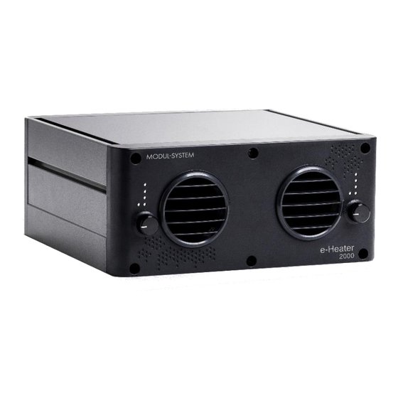
2. Product description The Modul-System e-Heaters are designed to efficiently heat both the load area and cab of your vehicle completely emission free. It is ideal for all light commercial vehicles (LCVs), particularly electric and hybrid models, including Battery Electric Vehicles (BEVs), Hybrid Electric Vehicles (HEVs), Plug-In Hybrid Electric Vehicles (PHEVs), and Range Extended Electric Vehicles (REEVs). -
Page 8: Rear
1. 12vdc Negative In 2. 12vdc Positive in 3. CAN communication port Figure 2 Rear of the e-Heater 1000/2000 This heater must in all cases be powered from an additional battery bank and NOT DIRECTLY from the vehicles Chassis battery. -
Page 9: Installation
Installation WARNING: Modul-System recommends that all wiring be done by a certified Technician or Electrician to ensure adherence to the applicable electrical safety wiring regulations and installation codes. Failure to follow these instructions can damage the unit and could also result in personal injury or loss of life. -
Page 10: Hose Ducting
2.1.2 Hose ducting With 28413-03 Hose kit 2m for e-Heater or 28414-03 Hose kit 4m for e-Heater, a hose can be attached to an outlet to duct the heat to a different area. The kits consist of: 1 x Air vent outlet for hose 1 x Neoprene Heater ducting 2m/4m 2 x Hose clamp 50-70mm Triple ball vent 50mm... -
Page 11: E-Heater Connection To Battery
1. Slide a hose clamp onto one end of the hose. 2. Attach the air vent outlet to the hose securely. 3. Position the clamp so it covers both the hose and the air vent connection, then tighten it firmly. 4. - Page 12 1. Fuse or Circuit Breaker: • The e-Heater 1000 must be fitted with 1 off in-line 100 amp fuse for the main battery connection on the positive +12 volt supply. • The e-Heater 2000 must be fitted with 1 off in-line 200 amp fuse for the main battery connection on the positive +12 volt supply.
-
Page 13: E-Heater Connection To Modul-Connect
‘Control/communication’ part. Fuse or Circuit Breaker: • The e-Heater 1000 must be fitted with 1 off in-line 100 amp fuse for the main battery connection on the positive +12 volt supply. • The e-Heater 2000 must be fitted with 1 off in-line 200 amp fuse for the main battery connection on the positive +12 volt supply. - Page 14 If the cord of the heater is damaged, it must be repaired by manufacturer or qualified electrician. • The e-Heater 1000 must be connected with input (Red) 25mm² cables. • The e-Heater 2000 must be connected with input (Red) 40mm² cables.
-
Page 15: Installation In Vehicle
2.4 Installation in vehicle 1. Choose an appropriate mounting location. 2. Ensure All fuses, fuse holders and connecting cables are the correct gauge to the product and position. 3. The e-Heater must be securely mounted on a metal or non-combustible surface. 4. - Page 16 Figure 8 e-Heater shelf bracket installation...
-
Page 17: Controlling The Heater
3. Controlling the heater There are three different options on how to control the e-Heater. 4.1 Control knob The e-Heaters can be managed using control knobs located on the front of the unit. By turning the knobs, the heater can be set to different target temperatures. -
Page 18: Switch Panels
The heater can be started by going into the sub-page of the widget. There run-time and target temperature can be set for the heater. There is also an option of only turning on the fan. At the bottom of the page, there is an option of adding schedule to automatically turn on and off the heater at certain times and days of the week. -
Page 19: E-Power
be used for controlling the e-Heater. By pressing on the heater switch button, the heater will start with the previously used target temperature and run for 30 minutes. There are more control options with the 24040-04 Display Switch Panel. By navigate to the heater page in the display, the desired target temperature and run time can be set. -
Page 20: Warranty
The limited warranty program is the only one that applies to this unit, and it sets forth all the responsibilities of Modul-System. There is no other warranty, other than those described herein. Any implied warranty of merchantability of fitness for a particular purpose on this unit is limited in duration to the duration of this warranty.
Need help?
Do you have a question about the e-Heater 1000 and is the answer not in the manual?
Questions and answers