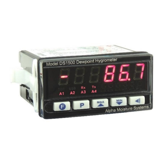
Summary of Contents for Alpha Moisture Systems DS1500
- Page 1 DS1500 RS485 / MODBUS Comms Alpha Moisture Systems DS1500 Dewpoint Hygrometer Display RS485 / MODBUS RTU Comms 3184 DS1500 Modbus Comms - User Manual...
-
Page 2: Contact Information
Email: info@amsystems.co.uk Website: amsystems.co.uk Office Opening Hours: Monday - Thursday 8.30am - 5.30pm (UK TIME) Friday 8.30am - 5.00pm Saturday and Sunday - Closed Authorised Distributor Contact Information © Alpha Moisture Systems - 3184 DS1500-Modbus – Issue 1 - October 2023... -
Page 3: Table Of Contents
3.2 Digital Output States ....…….………………………………………..13-14 Table 2- Digital output states ...…….………………………………………..14 Table 3- Error Codes ......…….………………………………………..14 4 Exception Responses – Error Conditions ..........14 5 RS485 / MODBUS RTU Wiring Location at the rear of the DS1500. 14-15... -
Page 4: Introduction
Observe the wiring diagram in Section 5, pages 14/15. Also refer to the wiring schematics in the DS1500 Dewpoint Hygrometer Display Manual – Section 6. Document Reference No. 3173. Do not connect the DS1500 to the power supply until it is in a permanent position. -
Page 5: Warranty
DS1500 RS485 / MODBUS Comms Risk of electric shock - Do not open any part of the DS1500 whilst connected to the power supply. Remove the power supply and isolate before any maintenance is carried out. The power supply terminals and associated internal circuitry are isolated from all other parts of the equipment in accordance with EN61010-1 for connection to a category II supply (pollution degree2). -
Page 6: Rs485 Interface
DS1500 RS485 / MODBUS Comms NOTE Please retain the original equipment packaging so the DS1500 can be returned to Alpha Moisture Systems or your authorised distributor if required. RS485 Interface • Compatible line signals with RS485 standard. • 2-wire connection between the master and up to 31 slave indicators in bus topology. -
Page 7: Configuration Of Serial Communication Parameters
DS1500 RS485 / MODBUS Comms The available Modbus commands are: 03 - Read Holding Register 05 - Force Single Coil (Force Digital Output state) 06 - Preset Single Register The registers are arranged in a table in such a way that several registers can be read in the same request. - Page 8 DS1500 RS485 / MODBUS Comms Maximum range: -31000 a 31000. The range depends of the showed display. 0005 Display Read: Current display number. Number Write: Not allowed. 0006 Status Read: Digital Inputs and Alarms (high part) and Word 1 Hardware type (low part).
- Page 9 DS1500 RS485 / MODBUS Comms bit 6 – Alarm 2 power-up inhibit (0 → No; 1 → Yes); bit 7 – Alarm 3 power-up inhibit (0 → No; 1 → Yes); bit 8 – Alarm 4 power-up inhibit (0 → No; 1 → Yes);...
- Page 10 DS1500 RS485 / MODBUS Comms → Configurable indication from 0 to +120000. 0017 Input Square Root. Range: 0 to 1. → No; → Yes. . 0018 4-20mA analog output on error condition. → Down;...
- Page 11 DS1500 RS485 / MODBUS Comms Range: 0 a 1. 0 → No; 1 → Yes. . 0030 Alarm 2 power-up inhibit. Range: Same as . . 0031 Alarm 3 power-up inhibit. Range: Same as . . 0032 Alarm 4 power-up inhibit.
- Page 12 DS1500 RS485 / MODBUS Comms configured in and the maximum is in configured. 0040 Indication High limit. Range: From to the input maximum configured in . 0041 Slave address. Range: 1 to 247.
-
Page 13: Digital Output States
DS1500 RS485 / MODBUS Comms . 0054 Low Limit for Analog Retransmission – Defines the PV value that results in a 4mA (or 0mA) analog output current. 0055 . High Limit for Analog Retransmission – Defines the PV value that results in a 20mA analog output current. -
Page 14: Exception Responses - Error Conditions
Table 3 – Error codes RS485 / MODBUS RTU Wiring Location at the rear of the DS1500 Please also refer to the DS1500 Dewpoint Hygrometer Display Manual – Section 9: Document Reference No. 3173 for further information. RS485 / MODBUS COMMS... - Page 15 DS1500 RS485 / MODBUS Comms Bidirectional data line Terminal 25 Inverted bidirectional Terminal 26 data line Optional connection. Terminal 27 Improves communication performance for long cable runs.


Need help?
Do you have a question about the DS1500 and is the answer not in the manual?
Questions and answers