Table of Contents
Advertisement
Quick Links
Advertisement
Table of Contents

Related Manuals for Alpha Moisture Systems DS5000


Summary of Contents for Alpha Moisture Systems DS5000
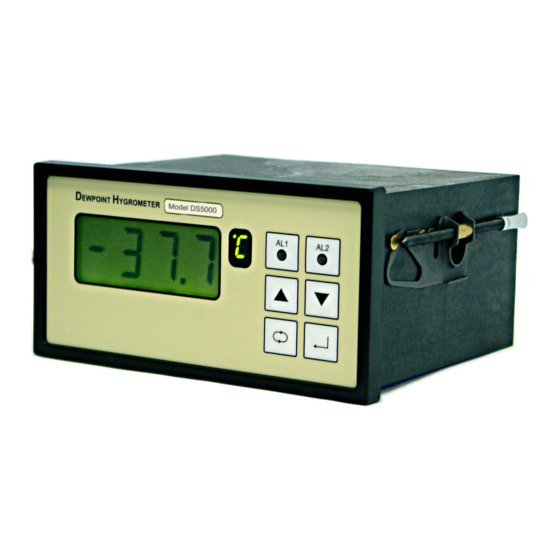
- Page 1 Document No:1188 Issue 2 Date 14/11/03 Model DS5000 Dewpoint Monitor Instruction Manual Alpha Moisture Systems Alpha House 96 City Road Bradford BD8 8ES England Tel: 01274 733100 Fax: 01274 733200 Email: info@amsystems.co.uk Web: WWW.amsytems.co.uk...
- Page 2 Instruction Manual for the DS5000 Dewpoint Monitor 1188 Instruction Man DS5000.doc Page ii...
-
Page 3: Table Of Contents
4-20 ............................9 VoLt ............................9 ACAL...........................10 oFSt............................10 CodE ............................11 9.10 InFo............................11 9.10.1 InFo- rmation Details......................12 Normal Operation of the DS5000 ................12 Pressure Correction ....................13 11.1 Examples..........................13 Monitoring the System....................13 Faults/Errors.......................14 13.1 Other Error mesages ......................14 DS5000 Specification....................15 Appendix A – Software Menu Map ................16 1188 Instruction Man DS5000.doc... -
Page 4: General Information
All the values are stored on the transmitter retaining the interchangeability of the transmitters. • The DS5000 has two full range alarms that can be set as rising or falling edge triggered. These alarms are visual (LED), audible and activate changeover relays for remote indication or control. -
Page 5: Installation
The screws must be tightened sufficiently to affect a seal between the front of the donor panel and the back of the instrument bezel, but never over tightened. 3.2 Instrument Wiring Wire the DS5000 as per figure 1.1 below. Alarm 1 Alarm 2... -
Page 6: Power Supply Cable
3.3 Power Supply Cable The DS5000 can be powered by either a 90-250V AC or 12V DC supply. Connect the required supply cable to the appropriate terminals as shown in figure 1.1. The AC power supply should be between 90 and 250V AC @ 50/60Hz. -
Page 7: Piping Installation Schematic
The sample tube should run upwards from the sample point. If this is not possible, then an inspection port or drain tap should be installed at the lowest point in the sample system. 1188 Instruction Man DS5000.doc Page 4 of 16... -
Page 8: Piping Schematic Component Index
Refer to the sample system schematic in section 4.1. Open the inlet isolation valve slowly, until a small flow of air/gas at atmospheric pressure flows through the inlet pipe work to the sensor holder and exhausts through the sensor entry port of the sensor holder. 1188 Instruction Man DS5000.doc Page 5 of 16... -
Page 9: Default Instrument Configuration
• All security codes are disabled. 7 Resetting the DS5000 It is possible to reset the DS5000 to factory set conditions by powering up the unit while any one of the four front panel keys is pressed. See ‘Default Instrument Configuration’ above for details of the default values. -
Page 10: Programming The Ds5000
Note – The Passwords used within the DS5000 are made off four integers and does not use the dp. Note – The only way to leave the numerical part of this routine without saving it is to allow the 60- second timeout to occur. -
Page 11: Bell
‘↵’ key. Note - If the ‘ ’ key is pressed instead of the ‘ ↵’ key the DS5000 will return to the ‘ AL 1 or AL 2’ screen on the base level, without saving any changes. -
Page 12: Volt
‘Hi’ or ‘ Lo’. Use the ‘ ’ key to select the high or low range limit whichever is required, and then press the ‘↵’ key. ’ key is pressed instead of the ‘ ↵’ key the DS5000 will re turn to the ‘VoLt’ screen on Note - if the ‘... -
Page 13: Acal
Operation – While ‘ACAL’ is displayed press the ‘ ↵’ key to enter the subroutine. If the DS5000 is set-up to require a security code, the LCD now displays ‘codE’ for 2 seconds followed by ‘0000’. Use the ‘ 5’, ‘ 6’, ‘ ’, & ‘ ↵’ keys to enter the current ACAL security code. -
Page 14: Code
‘SYS’. Use the ‘ ’ key to select the security password to be changed, and then press the ‘↵’ key. ’ key is pressed instead of the ‘ ↵’ key the DS5000 will return to the ‘ CodE’ screen on Note - If the ‘... -
Page 15: Info- Rmation Details
LED. If a pressure has been entered into the DS5000, the LED will alternate between the symbol for the currently selected engineering units and the ‘≡’ icon. This indicates that the m oisture values displayed on the LCD have been pressure corrected. -
Page 16: Pressure Correction
The system is designed to operate continuously, with a minimum amount of operator input. It is, however, advisable to inspect the sample loop periodically to ensure that the required pressures and flows are being maintained. 1188 Instruction Man DS5000.doc Page 13 of 16... -
Page 17: Faults/Errors
Should it be necessary, at any time or for whatever reason, to change either the instrument or sensor, it should be noted that the components of the DS5000/DT45 system are completely interchangeable. -
Page 18: Ds5000 Specification
Temperature Range: Electronics -10ºC to +60ºC Transmitter -10ºC to +50ºC EMC: Designed to meet the EMC and LVD directives. Diagnostics: Transmitter Open Circuit: ‘oPEn’ Transmitter short Circuit: ‘Shrt’ Comms Error: ‘conS 1188 Instruction Man DS5000.doc Page 15 of 16... -
Page 19: Appendix A - Software Menu Map
0000 0000 0000 0000 0000 0000 20.0 0000 0000 donE donE 0000 0000 -20.0 donE -25.0 Etcetera D ow n Sc ro ll E nte r A ut o (No action required) 1188 Instruction Man DS5000.doc Page 16 of 16...
Need help?
Do you have a question about the DS5000 and is the answer not in the manual?
Questions and answers