Table of Contents
Advertisement
Quick Links
Advertisement
Table of Contents

Related Manuals for Prestel VWC-HC14


Summary of Contents for Prestel VWC-HC14
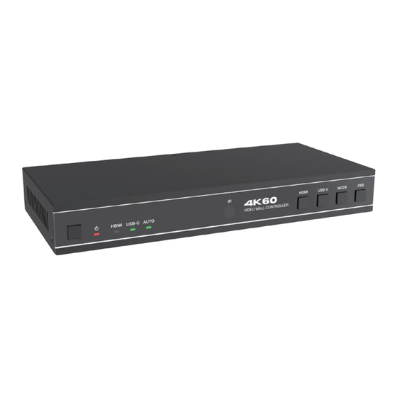
- Page 1 Prestel VWC-HC14 18Gbps 1x4 Video Wall Controller USER MANUAL...
-
Page 2: Table Of Contents
Thank you for purchasing this product For optimum performance and safety, please read these instructions carefully before connecting, operating or adjusting this product. Please keep this manual for future reference. Surge protection device recommended This product contains sensitive electrical components that may be damaged by electrical spikes, surges, electric shock, lighting strikes, etc. -
Page 3: Introduction
1. Introduction The 18Gbps 1x4 Video Wall Controller is designed to realize truely capturing, AD converting, routing, and distributing all-format signal to the video wall (LCD displays), while maintaining a true digital signal transmission. It features HDMI and USB-C input with resolution up to 4K@60 4:4:4, and 4 HDMI outputs. -
Page 4: Package Contents
3. Package Contents ① 1 × 18Gbps 1x4 Video Wall Controller ② 1 × 12V/1A Locking Power Supply ③ 1 × Power Adapter ④ 1 × IR Remote ⑤ 1 × 5V IR Receiver Cable (1.5m) ⑥ 1 × 3pin-3.81mm Phoenix Connector (male) ⑦... - Page 5 Human body model — ±8kV (Air-gap discharge) & ESD Protection ±4kV (Contact discharge) Connection 1 × HDMI INPUT [Type A, 19-pin female] Input ports 1 × USB-C INPUT [Type C, 24-pin female] 4 × HDMI OUTPUT [Type A, 19-pin female] Output ports 1 ×...
-
Page 6: Operation Controls And Functions
5. Operation Controls and Functions 5.1 Front Panel 3 4 5 Name Function Description In shutdown/standby status, press this button to power on; Power button in power-on status, press this button for 2~3 seconds to enter standby status. The LED will light in green when the product is working Power LED normally, and red when the product is on standby. - Page 7 5.2 Rear Panel INPUT AUDIO OUT VIDEO WALL OUT HDMI USB-C OPTICAL HDMI 1 HDMI 2 HDMI 3 HDMI 4 RS-232 IR EXT DC 12V Name Function Description HDMI signal input port, connected to an HDMI source HDMI INPUT device. USB-C signal input port, connected to a USB-C source USB-C INPUT device.
-
Page 8: Ir Remote
6. IR Remote Power on or Standby: Power on the device or set it to standby mode. Mute INPUT Mute: HDMI USB-C AUTO Turn off/on the audio output, including HDMI, Optical OUTPUT and L/R audio. Rotation HDMI: 720P 1080P Press to select HDMI input channel. VIDEO WALL USB-C: 1×1... -
Page 9: Ir Cable Pin Assignment
7. IR Cable Pin Assignment IR Receiver pin’s definition is as below: IR Receiver IR RECEIVER IR Signal Power Grounding 8. Video Wall Video wall supports 8 splicing modes as below: User can set display modes via front panel buttons, IR remote, and RS-232 commands. -
Page 10: Rs-232 Control Command
9. RS-232 Control Command The product also supports RS-232 command control. Connect the RS-232 port of the product to a PC with a 3-pin phoenix connector cable and an RS-232 to USB cable. The connection method is as follows. Ground 3-pin Phoenix Connector RS-232 RS-232 to USB cable... - Page 11 Command Function Example Feedback Default Setting Code Description System Setting mcu fw version : r fw version! Get firmware version r fw version! x.xx.xx power on system Power on/off the initializing... device, z=0~1 s power z! s power 1! initialization (z=0 power off, z=1 finished! power on)
- Page 12 Command Code Function Description Example Feedback Default Setting Input Setting Set input x edid mode (x=0~2, z=1~6) x=0. all input x=1. input1 x=2. input2 s input 1 input 1 edid: s input x edid z! z=1. 4k60, 2.0ch 4k60,2.0ch edid 1! 4k60, 2.0ch z=2.
- Page 13 Command Code Function Description Example Feedback Default Setting Output Setting tv wall Set tv wall horizontal s tw h tv wall horizontal s tw h bezel -! horizontal bezel bezel -! bezel: (bezel-1) bezel: 0 tv wall Set tv wall horizontal s tw h tv wall horizontal s tw h bezel x!
-
Page 14: Application Example
Command Code Function Description Example Feedback Default Setting Output Setting Set output audio mute s output audio on/off (x=0~1) s output output audio mute x! 0. mute off audio mute 0! mute: off 1. mute on r output audio Get output audio mute r output audio output audio mute!
Need help?
Do you have a question about the VWC-HC14 and is the answer not in the manual?
Questions and answers