Table of Contents
Advertisement
Quick Links
Advertisement
Table of Contents

Related Manuals for Prestel IPC-4KH2H265UKVM


Summary of Contents for Prestel IPC-4KH2H265UKVM
- Page 1 Prestel IPC-4KH2H265UKVM 4K60 H.264/H.265 AV over IP Controller USER MANUAL...
-
Page 2: Table Of Contents
Thank you for purchasing this product For optimum performance and safety, please read these instructions carefully before connecting, operating or adjusting this product. Please keep this manual for future reference. Surge protection device recommended This product contains sensitive electrical components that may be damaged by electrical spikes, surges, electric shock, lighting strikes, etc. -
Page 3: Introduction
1. Introduction This 4K@60 H.264/H.265 AV over IP controller supports fiber and copper, and supports automatic switching between two options, the copper has a higher priority. This controller can control and manage encoders and decoders over a standard 1G copper or fiber Network Switch. -
Page 4: Package Contents
3. Package Contents ① 1 x H.264/H.265 4K60 AV over IP Controller ② 2 x 6pin-3.81mm Phoenix Connector (male) ③ 1 x 3pin-3.81mm Phoenix Connector (male) ④ 1 x 12V 2.5A Locking Power Supply ⑤ 2 x Mounting Ear ⑥ 4 x Machine Screw (M3*4) ⑦... -
Page 5: Operation Controls And Functions
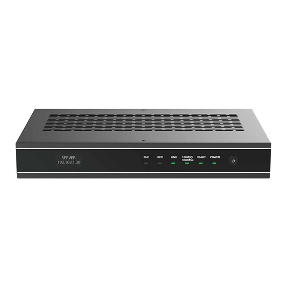
5. Operation Controls and Functions 5.1 Front Panel Name Function Description The name and IP address of the device will be displayed after OLED display the device is turned on. The screen will go off after 90 seconds. screen The Encoder mode indicator light, normally off. ENC LED DEC LED The Decoder mode indicator light, normally off. -
Page 6: Rear Panel
5.2 Rear Panel Name Function Description DC 12V/2.5A power input port. Note: The device can be powered via two methods: ① Local DC 12V power supply DC 12V ② POE from Network Switch. Device acts as PD mode. When the two power supply modes are used at the same time, the local DC 12V power supply is preferred. -
Page 7: Web Gui Operation Guide
6. Web GUI Operation Guide 6.1 Preparation before Entering the System The Controller can control IP products through Web GUI. The operation method is shown as below: Step 1: Connect the Controller, PC, encoders, decoders, signal source devices and display devices the same Switch. -
Page 8: Functions And Operation
6.2 Functions and Operation ■ Home Page The Home page shows the current operating status of the Web GUI. The page is divided into 7 parts: Signal, Decoder, Display Wall, System State Diagram, Disk Usage, Shortcut, and Message Center. Users can immediately return to the Home page by clicking the button in the upper left corner. - Page 9 1) Reboot Service: Click this button to reboot the Server process. 2) Reboot Server: Click this button to reboot the current Server Host. 3) Get License Info: Click this button to obtain the authorization details for the Server. 4) Get Hardware Info: Click this button to obtain the Server hardware information for authorization.
- Page 10 • System State Diagram, Disk Usage The system state diagram displays the codec computability, network bandwidth and TDP(W). The Server disk occupancy/remaining capacity is updated in real time. • Shortcut Sort the recently used Display Walls by usage frequency for user convenience. You can quickly turn on/off the Display Wall by clicking the button ;...
-
Page 11: Topchart Page
■ TopChart Page The system TopChart is automatically generated by the system. It is a true reflection of the real-time working status of all current devices. When there are many devices in the system, you can use the mouse to drag or scroll up and down the TopChart. •... - Page 12 • Signal Source Grouping Click “Group” to switch to the group mode, and click “List” to switch to the list mode. • Create Subdirectory The default display of signal source group is the root directory. Select the root directory, click “Create Subfolder”, then enter the directory name in the pop-up box, finally click “Confirm”...
- Page 13 • Signal Source Information Display 1) Online/Offline: The current status of all signal sources. 2) Video/Audio Encoder: The status of video/audio signal sources. 3) Warning Information: Display warning information based on device temperature and other parameters. 4) Fault Information: Display fault information based on the reported device working status. •...
- Page 14 Device Name: The name of the selected encoder device, automatically generated, supporting being edited and modified directly. MAC: The MAC address of the selected encoder device. Version: The version of the selected encoder device. Video Codec Format: The video sampling format can be set to “YUV420”, “YUV422” or “YUV444”.
- Page 15 Device Name: The name of the selected encoder device, automatically generated, supporting being edited and modified directly. Reset: Only system administrators have this permission, and this button will not be displayed for other users. Video Colorspace: The color of the video input signal can be set, including brightness, hue, contrast, saturation and sharpness.
-
Page 16: Ipc Page
• Signal Source Batch Process Select the signal sources that needs to be processed in the signal source list, and then select “Firmware Update”, “Delete Device”, or “Reboot Device” in the drop-down menu of Batch Process to complete the batch process. •... - Page 17 Confirm that there is no error, you can click the “Import IPC” button to upload to the Server. Then the information will be imported and displayed on the page, in which the original IPC signal list will be overwritten. • IPC Signal Management After successfully uploading, you can click “preview”...
-
Page 18: Decoder Page
■ Decoder Page This page displays the overall operating status of all decoders, as well as warning and fault information for all decoders. The detailed information of each decoder is displayed in the list on this page. Users can edit and restart each decoder. •... - Page 19 2) Decoder Basic Settings Device Name: The name of the selected decoder device, automatically generated, supporting being edited and modified directly. MAC: The MAC address of the selected decoder device. Version: The version of the selected decoder device. Output Resolution: The output resolution of the decoder, which can also be selected from presets.
- Page 20 3) Decoder Advanced Settings Click the “Advanced” tab to switch to the advanced settings page. Device Name: The name of the selected decoder device, automatically generated, supporting being edited and modified directly. Reset: Only system administrators have this permission, and this button will not be displayed for other users.
-
Page 21: Displaywall Page
■ DisplayWall Page This page is responsible for managing all large screens, including create, edit, open, close, schedule, and delete DisplayWalls. • Create DisplayWall Click “Create DisplayWall” to pop up the following dialog box. Set the parameters for the DisplayWall in the above box, and then click the “Save” button to create the DisplayWall. - Page 22 • Edit DisplayWall Select a DisplayWall and click “Edit” to enter the editing page, mainly including three functions: bind audio and video decoders to various areas of the DisplayWall, edit DisplayWall parameters, and upload the background image. 1) Bind Audio and Video Decoders Select the decoder from the Video Decoder list on the left, drag and drop it to the correspond- ing area of the DisplayWall to complete the binding;...
- Page 23 Set the parameters for the DisplayWall in the above dialog box, and then click the “Save” button to complete editing. The settings will take effect immediately. 3) Upload Background Image Click the drop-down menu icon in the top right corner, and select “Upload Background” to pop up the Background Image Configure dialog box.
- Page 24 • DisplayWall Dispatch Click “Dispatch” to enter the scheduling page of the DisplayWall, which is a new browser window. There is a list of resources on the left side, including video signal, audio signal, mosaic encoder, layout and marquee. The central area of the page is the large screen operation area.
- Page 25 Open Window Operation Process: Step 1: Select a signal source from the list of signal sources on the left using the mouse. Step 2: Hold down the left mouse button and drag the signal source to any area within the DisplayWall.
- Page 26 Close Audio Process 1: Step 1: Find the signal of the audio being played in the video or audio signal source list. Step 2: Click the horn icon to turn off the audio. Close Audio Process 2: Step 1: Click on the blank area of the large screen, and the property bar on the right will display the current properties of the large screen.
- Page 27 Delete Layout Process: Step 1: Select the layout to be deleted from the layout list on the left. Step 2: Click the drop-down menu icon to select “Delete Layout” in the drop-down menu. Create Auto Layout Process: Step 1: Click the drop-down menu icon to select “Create AutoLayout” in the drop-down menu. Step 2: Enter the auto-layout name in the Create Auto-Layout dialog box.
- Page 28 Marquee Edit Items: Name: The name of the marquee. Alignment: The position of the marquee content on the DisplayWall. Offset: The display coordinates of the marquee on the DisplayWall. Size: The size of marquee area. Transparent: Turning on the switch indicates that the marquee is transparent; If the switch is turned off, the marquee is not transparent.
-
Page 29: Mosaic Page
Edit Marquee Process: Step 1: Select the marquee to be edited from the marquee list on the left. Step 2: Click the drop-down menu icon to select “Edit Marquee” in the drop-down menu. Step 3: Modify the marquee configuration in the pop-up editing box as required, and click the “Save”... -
Page 30: Peripherals Page
Mosaic Edit Items: Name: The name of the mosaic. Row & Column: The numbers of row and column of the mosaic. Width & Height: The encoding width and height of each encoder. After filling in the above parameters, a blank grid will be displayed in the middle drawing area. Use the mouse to drag the encoder on the right to the corresponding grid in the drawing area (as shown in the following figure). - Page 31 Device Driver Edit Items: Name: The display name of the device driver. The maximum length is 32 English characters or 16 Chinese characters. Ctrl Mode: The communication method (COM) used by the device driver. Format: The communication protocol format, including ASCII, HEX, JSON and XML. Icon: The driver display icon.
- Page 32 After adding the above items, click the “Save” button. • Edit Driver Select the driver to be edited from the left driver list, then click the drop-down menu button in the upper right corner to pop up the editing menu (as shown in the following figure). Select “Edit Driver”...
- Page 33 After successful creation, it will appear in the device list (as shown in the following figure). • Test New Device Click the “Test” button behind the device in the device list to pop up the Test Device Dialog box. Select the function to be tested, fill in the appropriate parameters in the parameter list, and click the “Test”...
-
Page 34: Scene Page
■ Scene Page The scene is mainly a functional module used to customize the interface of visualization software. The scene page contains three modules: scene, task and trigger. • Scene There are two types of scenes: login scene and main scene. There is no difference in editing between the two scenes, only the applications are different. - Page 35 3) Export Scenes Click the “Export Scenes” button in the bottom left corner, then the system will package and download all scenes, tasks, triggers, device drivers and devices in the current system locally. 4) Import Scenes Click the “Import Scenes” button in the bottom left corner, then the system will delete all scenes, tasks, triggers, device drivers and devices in the current system, and recreate them according to the imported file.
- Page 36 3) Copy Task In the task list, click the “Copy” button to pop up the Copy Task dialog box. Input the new task name, then click the “Save” button to take effect. 4) Delete Task In the task list, click the “Delete” button to pop up the Delete Task dialog box, then click the “OK”...
-
Page 37: Account Page
Execute Actions: Driver Type: The driver of the execute device after the trigger condition is met. Execute Device: The name of the execute device after the trigger condition is met. Function: The functional instructions executed by the device after the trigger condition is met. Param: Parameters in the functional instructions executed by the device after the trigger condition is met. - Page 38 1) Create Account Click the “+ Create Account” button in the top right corner to pop up the Create User dialog box. Select the user type, input the username, password and telephone number, then click the “Save & Config Permission” button to pop up the Permission Configure dialog box. 2) Permission Configure In the account list, click the “Permission Configure”...
-
Page 39: Application Example
7. Application Example Input Output Laptop Control Server Transceiver (ENC Mode) Transceiver (DEC Mode) HDMI Cable Network Network Cable Cable Transceiver (DEC Mode) HDMI Cable Video Wall HDMI Cable Laptop Transceiver (ENC Mode) Network Cable Transceiver (DEC Mode) Network Cable HDMI Cable HDMI Cable Transceiver (DEC Mode)
Need help?
Do you have a question about the IPC-4KH2H265UKVM and is the answer not in the manual?
Questions and answers