
Subscribe to Our Youtube Channel
Related Manuals for IRIS IO SmartHub


Summary of Contents for IRIS IO SmartHub
- Page 1 IO SmartHub™ UG240703 IO SmartHub™ QuickStart Guide ©2024 Iris Dynamics, Ltd. Victoria, British Columbia T +1 (888) 995-7050 irisdynamics.com pg. 1 of 9...
-
Page 2: Table Of Contents
IO SmartHub™ UG240703 CONTENTS Revision History...............................2 How do I connect the IO SmartHub to my Orca Series motor?............. 3 Connecting to a PLC / Microcontroller...................... 4 Troubleshooting Connections..........................5 Motor Not Moving / Staying in Sleep Mode..................5 No Connection to Orca Series Motor....................5 Incorrect Analog Input / Output Values....................5... -
Page 3: How Do I Connect The Io Smarthub To My Orca Series Motor
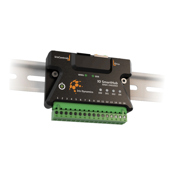
How do I connect the IO SmartHub to my Orca Series motor? To connect the IO SmartHub to an Orca Series motor and establish communications, plug the male RJ45 connector from the motor into the shielded female RJ45 jack on the SmartHub. -
Page 4: Connecting To A Plc / Microcontroller
At a minimum, the V+ and V- terminals of the SmartHub must be connected to a 12-30 V power supply. If the IO SmartHub is correctly connected to a 12-30 V power supply, the amber power light will be illuminated. -
Page 5: Troubleshooting Connections
● Verify that the connected Orca Series motor firmware version is 6.2.8 or higher. Incorrect Analog Input / Output Values ● Ensure the field powered side of the IO SmartHub is powered with 12-30 V across the V+ and V- terminals. -
Page 6: Configuration
UG240703 Configuration Configuration for operation with an IO SmartHub is stored and saved in the nonvolatile memory of Orca Series motors, not the SmartHub itself. The actual data transmitted between the SmartHub and a motor does not change with configuration, only the way it is interpreted by the motor. -
Page 7: Digital Input Status
4-20 mA or 0-20 mA. Kinematic Trigger Settings Selects the kinematic motion IDs that will be triggering on rising and/or falling edges of digital input trigger signals. ©2024 Iris Dynamics, Ltd. Victoria, British Columbia T +1 (888) 995-7050 irisdynamics.com... -
Page 8: Input Modes
Digital Input 2 Reserved Reserved Trigger 3 Digital Input 3 Enable Enable Enable Analog Input Force Command Position Command Reserved (Max Force when DI1 high) ©2024 Iris Dynamics, Ltd. Victoria, British Columbia T +1 (888) 995-7050 irisdynamics.com pg. 8 of 9... -
Page 9: Warning And Error Signals
Sleep Mode, which attempts to clear various errors. If the error condition still exists on the motor, the error signal will persist. In this case, further investigation on the state of the motor is required. ©2024 Iris Dynamics, Ltd. Victoria, British Columbia T +1 (888) 995-7050 irisdynamics.com...
Need help?
Do you have a question about the IO SmartHub and is the answer not in the manual?
Questions and answers