Table of Contents
Advertisement
Quick Links
Orca™ IO SmartHub
UG230424
Orca™ IO SmartHub
User Guide 230424
Version 1.1, Feb 2024
This document applies to the following Orca Series motor firmware:
● 6.2.8
For more recent firmware versions, please download the latest version of this user guide at
https://irisdynamics.com/downloads
Contact info@irisdynamics.com for additional information
pg. 1
Iris Dynamics Ltd.
Victoria, British Columbia
T +1 (888) 995-7050
F +1 (250) 984-0706
www.irisdynamics.com
Advertisement
Table of Contents

Subscribe to Our Youtube Channel
Related Manuals for IRIS Orca IO SmartHub


Summary of Contents for IRIS Orca IO SmartHub
- Page 1 ● 6.2.8 For more recent firmware versions, please download the latest version of this user guide at https://irisdynamics.com/downloads Contact info@irisdynamics.com for additional information pg. 1 Iris Dynamics Ltd. Victoria, British Columbia T +1 (888) 995-7050 F +1 (250) 984-0706 www.irisdynamics.com...
-
Page 2: Table Of Contents
GUI Element Descriptions........................10 Current Loop Status...........................10 Digital Input Status..........................11 Save Configuration Button........................11 Force Range Setting.......................... 11 Position Range Setting........................11 Orca IO SmartHub Mode Selection....................11 Current Range Selection........................11 Kinematic Trigger Settings....................... 11 Input Modes..............................12 Force Mode..............................12 Position Mode............................12 Kinematic Mode............................ -
Page 3: Revision History
Dec, 2023 rm, sj Rebranding, support with v6.1.8 orca firmware Feb, 2024 sj, rm, kc Update diagrams and renders Contact info@irisdynamics.com for additional information pg. 3 Iris Dynamics Ltd. Victoria, British Columbia T +1 (888) 995-7050 F +1 (250) 984-0706 www.irisdynamics.com... -
Page 4: Overview
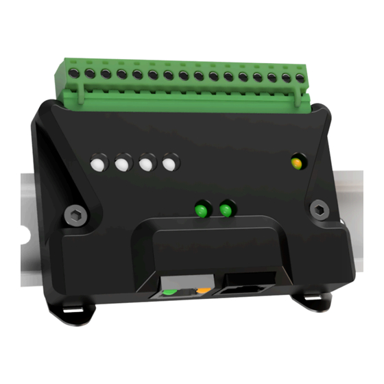
Position, and Kinematic Modes through simple digital and analog inputs. Real-time force and position data are also fed back from the motor to the Orca IO SmartHub and provided as analog outputs. The Orca IO SmartHub handles the high-speed digital communication with the motor, allowing easier integration with existing industrial control methods such as PLCs with 4-20 mA current loop outputs. - Page 5 = Rx Rx/Tx Indicator Lights Yellow = Tx IrisControls For connecting to Orca Series motor GUI through IrisControls. Passthrough Contact info@irisdynamics.com for additional information pg. 5 Iris Dynamics Ltd. Victoria, British Columbia T +1 (888) 995-7050 F +1 (250) 984-0706 www.irisdynamics.com...
-
Page 6: Pinout
Shaded groups of pins share an isolated common pin that must be connected to the appropriate ground for the circuit they are interfacing with. Contact info@irisdynamics.com for additional information pg. 6 Iris Dynamics Ltd. Victoria, British Columbia T +1 (888) 995-7050 F +1 (250) 984-0706... -
Page 7: External Connections
Orca™ IO SmartHub UG230424 External Connections Figure 3: Orca IO SmartHub Connection Diagram Contact info@irisdynamics.com for additional information pg. 7 Iris Dynamics Ltd. Victoria, British Columbia T +1 (888) 995-7050 F +1 (250) 984-0706 www.irisdynamics.com... -
Page 8: Connecting To An Orca Series Motor
5-30 V DC. At a minimum, the V+ and V- terminals of the Orca IO SmartHub must be connected to a 5-30 V power supply. If the Orca IO SmartHub is correctly connected to a 5-30 V power supply, the amber power light will be illuminated. -
Page 9: Troubleshooting Connections
Verify that the connected Orca Series motor firmware version is 6.2.8 or higher. ● Incorrect Analog Input / Output Values Ensure the field powered side of the Orca IO SmartHub is powered with 5-30 V across ● the V+ and V- terminals. -
Page 10: Configuration
Orca IO SmartHub and a motor does not change with configuration, only the way it is interpreted by the motor. This means that any Orca IO SmartHub can be plugged into a given motor and the same behaviour should be expected. -
Page 11: Digital Input Status
20 mA. Position values below the minimum or above the maximum will be clipped to their respective current. Orca IO SmartHub Mode Selection Determines how the motor will respond to the analog and digital inputs. See the Input Modes section for more information. -
Page 12: Input Modes
(Max Force when DI1 high) Force Mode In Force Mode, while connected to an Orca IO SmartHub, an Orca Series motor will stay in Sleep Mode while the Enable input is held low. If the Enable line is held high, the motor will enter mode 8, Analog Force Mode. -
Page 13: Kinematic Mode
Once a position value is calculated, it is sent to the motor’s position controller as a command. While Digital Input 1 is held high, the Analog Input channel of the Orca IO SmartHub will instead be converted into a force saturation value . -
Page 14: Warning And Error Signals
Warning and Error Signals The Orca IO SmartHub has two digital output pins assigned as warning and error. They act as signals that can be fed into an external controller to detect error states on the connected motor. - Page 15 In this case, further investigation on the state of the motor is required. Contact info@irisdynamics.com for additional information pg. 15 Iris Dynamics Ltd. Victoria, British Columbia T +1 (888) 995-7050 F +1 (250) 984-0706...
Need help?
Do you have a question about the Orca IO SmartHub and is the answer not in the manual?
Questions and answers