
Related Manuals for MPS GESINT EWM


Summary of Contents for MPS GESINT EWM
- Page 1 GESINT GESINT GESINT GESINT ® ® ® ® PULSE COUNTER & BATCH CONTROLLER INSTALLATION AND CONFIGURATION MANUAL Rev. 0.9 - 19/10/2023...
-
Page 2: General Recommendations
GENERAL RECOMMENDATIONS To install and use the EWM pulse counter correctly and safely, it is necessary read and follow the instructions contained in this manual. This device can be connected to other equipment, which could be dangerous if used improperly. Read and follow the instructions before use such equipment with this device. -
Page 3: Front Side
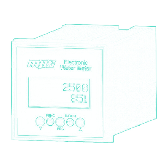
FEATURES This device is equipped with a backlit LCD display which provides optimal readability. It also has two LED for instrument status display. Programming functions are controlled using the 3 buttons “▼” + “PRG” + “▲” , the 2 multifunctional LED “FUNC” + “BATCH” present on the front side, and indications provided by the 2 rows display. -
Page 4: Collegamenti Elettrici
COLLEGAMENTI ELETTRICI Always make sure to unplug the power supply before operating on the device’s electrical connections. Strip the ends of the cable (about 5mm) and tin it in order to avoid cable fraying. It is preferable to use ferrules when connecting more than one cable to the same space in the terminal block. -
Page 5: Flow Sensor Connection
FLOW SENSOR CONNECTION FIP F3.00.F/H - IP65 - DIN43650A FIP F3.00.F/H - IP68 - CAVO Ext_res Ext_res Verde Marrone Bianco +12V +12V FIP F3.00.P - Push-Pull G+F MK515PO - Coil Ext_res Ext_res Rosso Nero +12V +12V OPTO (Sensus OD) REED pulser Ext_res Ext_res Marrone... -
Page 6: Device Use
DEVICE USE The EWM, once powered, una volta alimentato, is immediately operational Sulle 2 righe del display sono riportate le informazioni relative allo stato corrente. Information related to the current status is shown on the 2 rows display. The first line shows the operating mode (A for Automatic or M for Manual) and the value of the volume to be transferred (set-point), while the bottom line shows the volume tran- sferred up to the current moment. - Page 7 MANUAL MODE To start or stop a transfer operation, the operator must press and release the PRG button. When the PRG key is pressed for the first time, OUT1 output is activated and • the "func" LED on the front of the device will turn GREEN. This operation is typically associated with the opening of a valve.
-
Page 8: Parameters Setup
PARAMETERS SETUP To change device parameters, press the ▼ and ▲ buttons simultaneously for at least 2 seconds. Once entered in the setup menu, select parameters by pressing the PRG • button and change its value with the ▼ and ▲ buttons The first screen displays the parameter name to be changed, and by waiting •... - Page 9 MENU SCHEMA FOR PARAMETERS SETUP Wait 2 seconds Press PRG or wait 2 seconds Read-only, not resettable. Press PRG Press PRG or wait Press 2 seconds ▼ or ▲ Working mode Manual/Automatic Press PRG Press ▲ or ▼ to manually Press PRG or adjust K-Factor value wait 2 seconds...
- Page 10 Parameters setup, follow from previous page Press PRG or wait 2 seconds Press PRG or wait 2 seconds OUT2 pulse duration, in milliseconds Press PRG Volume value for Press PRG or OUT2 pulse wait 2 seconds Press PRG Press ▲ to save changes or ▼ for not saving. Device then returns to home screen.
- Page 11 AUTOMATIC K-FACTOR EVALUATION If K-Factor is set to 0 (zero), device can evaluate the current K-Factor after transfer ring a knows volume of liquid. Press PRG START transfer with PRG button transfer with PRG button Press PRG or wait 2 seconds Insert amount (in liters or other unit) of the liquid transferred...
- Page 12 RESET COUNTER IN AUTOMATIC (A) WORKING MODE Press PRG for 2 seconds Press PRG or wait 2 seconds Press ▼ or ▲ RESTART TRANSFER IN MANUAL (M) WORKING MODE AFTER POWER FAILURE Wait 5 seconds Press ▼ to restart transfer from the beginning (zero) or ▲...
- Page 13 TECHNICAL DATA Housing Black PPO, self-extinguishing Display Back-lit dot matric 2x8 chars Power supply 24Vac/dc (50-60Hz) – 100mA with galvanic isolation Recommended use of protection filters on power supply Working temperature: from 0° to 50°C Storage temperature: from -10° to 70°C Relative humidity: Max 80% –...
- Page 14 REPLACEMENT SCHEMA FROM C-210 TO EWM C-210 Working mode AUTO Power Supply PIN 2 PIN 10 Flow sensor FIP F3.00.F or F3.00.H PIN 3 PIN 6 PIN 1 N/P & +12V (bridge) Flow sensor G+F MK515PO PIN 1 PIN 6 Relay Output 1 (end transfer) PIN 9 Out 1...
- Page 15 REPLACEMENT SCHEMA FROM CNT-10 TO EWM CNT-10 Working mode AUTO Power Supply PIN 1 PIN 2 Flow sensor FIP F3.00.F or F3.00.H PIN 2 (rif. 0V) PIN 3 PIN 4 N/P & +12V (bridge) Flow sensor G+F MK515PO PIN 5 PIN 6 Shield Connect to general ground...
- Page 16 REPLACEMENT SCHEMA FROM F9.10 TO EWM F9.10 Working mode AUTO Power Supply PIN 1 PIN 4 Flow sensor FIP F3.00.F or F3.00.H PIN 5 PIN 6 PIN 7 N/P & +12V (bridge) SSR Output (pulse divider) PIN 8 Out 2 PIN 9 Out 2 Relay Output 1 (transfer)
Need help?
Do you have a question about the GESINT EWM and is the answer not in the manual?
Questions and answers