
Related Manuals for SYSCON SENSORS CC-1

Summary of Contents for SYSCON SENSORS CC-1
- Page 1 CC-1 Calibration Checker User Manual www.sysconsensors.com 1108 High Street South Bend, IN 46601 +1 (574) 232-3900...
-
Page 2: Table Of Contents
S-Type: ......................11 K-Type: ......................12 Lance Check ...................... 13 Curve mode ....................... 14 Settings mode ....................15 Calibration Mode ....................16 Technical Circuit Information ................... 17 Instrument Returns ....................18 Calibration Certificate ....................19 Revision 5 © SYSCON Sensors... - Page 3 Verification of Calibration ..................22 Instructions on performing Verification of Calibration ........... 22 Instructions on using the Verification of Calibration Template ....... 22 Troubleshooting ...................... 26 Preliminary Check ....................26 Troubleshooting CC-1 ..................26 Revision 5 © SYSCON Sensors...
-
Page 4: List Of Figures
Figure 13: Lance check when insulation is less than 1M ......13 Figure 14: Sample cooling curve plotted on an FL-1 ........14 Figure 15: CC-1 panel showing the progression of the cooling curve test ..15 Figure 16: CC-1 in Settings mode (K-90) ............15 Figure 17: CC-1 in Settings mode (S-68) ............ -
Page 5: List Of Tables
List of Tables Table 1: Thermocouple comparison (types S and K)........3 Table 2: Button and LED description ..............7 Table 3: Instrument configurations available ..........7 Table 4: Troubleshooting ................26 Revision 5 © SYSCON Sensors... -
Page 6: Before You Start
The user manual cannot cover all possible cases of installation, operation and maintenance. Contact SYSCON Sensors for application specific assistance. Revision 5 © SYSCON Sensors... -
Page 7: Introduction
Introduction The SYSCON Sensors CC-1 calibration checker provides instant validation of calibration for handheld digital pyrometers, wall mounted digital pyrometers and metallurgical analyzers. The device can be configured and calibrated for two sets of temperatures depending on which temperature scale (Celsius or Fahrenheit) the user needs. Temperatures for each of these modes are listed in Table 3. -
Page 8: Specifications
Battery 3.7 V 2500mAh, Lithium-Ion Polymer battery Battery Life 125 hours on full charge 100 - 240 V 60 Hz AC Input Battery Charger 5 V 1A DC Output Housing IP 65 rated instrument box Ambient Humidity 0 to 90% non-condensing Revision 5 © SYSCON Sensors... -
Page 9: Application
Application The CC-1 Calibration Checker is used to validate the calibration of handheld digital pyrometers, wall mounted pyrometers and metallurgical analyzers that use S or K type thermocouples. The CC-1 outputs a compensated voltage that corresponds to standard temperatures for S and K type thermocouples. There is a provision to output a curve that approximates a real cooling curve which can be used with metallurgical analyzer type instruments. -
Page 10: Setup
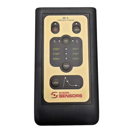
The Calibration Checker’s front panel includes a set of buttons and LEDs that show the test device’s state. It has a multi-plug socket that can be used to connect the CC-1 to the instrument to be tested. The front panel in Figure 1 corresponds to a device that is configured for temperatures corresponding to Fahrenheit scale Table 3, shows temperatures applicable for each mode. -
Page 11: Figure 2: S- And K-Type Connector Cables
K-type thermocouples. Figure 2: S- and K-type connector cables • Case for instrument and cable A hard-shell case is provided for conveniently storing the Calibration Checker, test leads, and micro-USB charger. Revision 5 © SYSCON Sensors... -
Page 12: Instrument Operation
Figure 3 and Figure 4 show the configurations available for the device. Table 2 shows and explains the various LED and buttons on the instrument panel. Figure 4: Instrument Figure 3: Instrument Panel and LEDs for Panel and LEDs for Fahrenheit mode Celsius mode Revision 5 © SYSCON Sensors... -
Page 13: Table 2: Button And Led Description
Fahrenheit S Type 3050 °F 2700 °F 2450 °F K Type 2250 °F 2150 °F 2050 °F Celsius S Type 1300 °C 1500 °C 1700 °C K Type 1100 °C 1200 °C 1300 °C Revision 5 © SYSCON Sensors... -
Page 14: Instrument Startup Cycle
Instrument startup cycle Pressing the POWER button turns the CC-1 ON, and a green LED is lit on top of the power button to indicate that the instrument is switched on. The instrument then shows the calibration standard [IPTS 48, 68, 90], which can be different for S type vs K type. The following figures Figure 5, Figure 6 and Figure 7 show how the calibration settings are indicated at the startup cycle. -
Page 15: Figure 8: Startup Showing Device Is In Fahrenheit Mode
Fahrenheit mode Figure 8. After the settings are shown, the instrument moves to an idle state. Figure 9: Startup showing Figure 8: Startup showing device is in Celsius mode device is in Fahrenheit mode Pressing the power button once again will power down the instrument. Revision 5 © SYSCON Sensors... -
Page 16: Idle Mode
In this mode, the T/C type LED shows the thermocouple selected and shorts the output of the CC-1. Refer to Figure 10 which shows the instrument in idle mode with an S-type thermocouple output selected. Shorting the output of the CC-1 will cause the instrument being tested [TS-1, WM-1 or FL-1] to move to a ready status. -
Page 17: T/C Mode
Pressing T/C button switches the CC-1’s output between S- and K-type thermocouple. Pressing this button will stop the current action being performed by the unit and shorts the output of the CC-1. This will cause handheld and wall mounted instruments to go to ready status. -
Page 18: K-Type
When the TEMP button is pressed, the instrument starts a step curve starting at 2250°F followed by 2150°F followed by 2050°F. In-between these temperatures, CC-1 output will NOT be shorted. The length of time these outputs are held is not the same. Refer to Figure 12 for a sample of the square curve. -
Page 19: Lance Check
1M, the red LED is on the Lance button [Figure 13]. This is indicative that the wiring in the lance/contact block has failed. Figure 13: Lance check when insulation is less than 1M Revision 5 © SYSCON Sensors... -
Page 20: Curve Mode
Lance button will stop plotting the curve and simulate a cup removal. The three LEDs on the curve graphic will light up to show this. The CC-1 instrument will then move to idle mode. The Lance LEDs will not light up for this operation. -
Page 21: Settings Mode
Figure 15: CC-1 panel showing the progression of the cooling curve test Settings mode This mode is used to change the IPTS settings for S- and K-type. Pressing the TEMP and Curve buttons at the same time will put the device in this mode Figure 16. Pressing the T/C button allows the user to move between S- and K-type thermocouples. -
Page 22: Calibration Mode
Calibration Mode This mode is used in the factory to calibrate the CC-1. If the user goes into this mode, it does not affect the CC-1’s calibration. Pressing the T/C and TEMP buttons will put the device in this mode [Figure 19]. All buttons except POWER button are inactive in this mode and the device will go to idle mode after 5 minutes. -
Page 23: Technical Circuit Information
PC. This chip also enables switching between power supply and battery if CC-1 needs to be used while charging. The yellow LED on the power button is lit to show that the device is charging. When charging is complete the LED will switch off. -
Page 24: Instrument Returns
Instrument Returns The CC-1 Calibration Checker must itself be returned to the factory once per year so that its own calibration can be set and verified. Upon annual calibration of the CC-1, a new NIST referenced calibration certificate will be issued (see Figure 20 thru Figure 21) for the Calibration Checker itself, allowing it to be used for the subsequent 12 months to issue valid calibration certificates for field instruments. -
Page 25: Calibration Certificate
Calibration Certificate A sample Calibration Certificate followed by report of calibration in both Celsius and Fahrenheit mode are shown through Figure 20 to Figure 22. Figure 20: Certificate of Calibration for CC-1 Revision 5 © SYSCON Sensors... -
Page 26: Figure 21: Report Of Calibration For Celsius Mode
Figure 21: Report of Calibration for Celsius mode Revision 5 © SYSCON Sensors... -
Page 27: Figure 22: Report Of Calibration For Fahrenheit Mode
Figure 22: Report of Calibration for Fahrenheit mode Revision 5 © SYSCON Sensors... -
Page 28: Verification Of Calibration
• If the DUT is a FL-1, check the settings for each individual channel by going to Config -> enter password -> chan. TC type and TC Calib rows will show the settings. • Set the CC-1 to the right IPTS setting [48,68,90] and TC type for the DUT (refer to the section on TC mode, settings mode). - Page 29 • Technician: Name of technician running the test • Date Verified: Date when the test is run • Instrument Used table: Data from the calibration certificate of the CC-1 being used • Test results table: For TS-1/WM-1 template [Figure 23], results observed on the test run corresponding to ▪...
-
Page 30: Figure 23: Verification Of Calibration Ts-1/Wm-1 In Fahrenheit Mode
Figure 23: Verification of Calibration TS-1/WM-1 in Fahrenheit mode Revision 5 © SYSCON Sensors... -
Page 31: Figure 24: Verification Of Calibration Fl-1 In Fahrenheit Mode
Figure 24: Verification of Calibration FL-1 in Fahrenheit mode Revision 5 © SYSCON Sensors... -
Page 32: Preliminary Check
• Charge the unit via the USB port. • If the unit won’t power on after that, return instrument for repairs. DUT will not show Temperature/Curve • Abort the current CC-1 cycle and return ready, CC-1 is in mode was started to Idle mode. Temperature/Curve early.
Need help?
Do you have a question about the CC-1 and is the answer not in the manual?
Questions and answers