Table of Contents
Advertisement
Quick Links
GA-K8NS Ultra-939
AMD Socket 939 Processor Motherboard
User's Manual
Rev. 1002
12ME-K8NSU939-1002
Copyright
© 2004 GIGABYTE TECHNOLOGY CO., LTD
Copyright by GIGA-BYTE TECHNOLOGY CO., LTD. ("GBT"). No part of this manual may be reproduced or transmitted in any from
without the expressed, written permission of GBT.
Trademarks
Third-party brands and names are the property of their respective owners.
Notice
Please do not remove any labels on motherboard, this may void the warranty of this motherboard.
Due to rapid change in technology, some of the specifications might be out of date before publication of this booklet.
The author assumes no responsibility for any errors or omissions that may appear in this document nor does the author make a
commitment to update the information contained herein.
Advertisement
Table of Contents

Related Manuals for Gigabyte GA-K8NS Ultra-939


Summary of Contents for Gigabyte GA-K8NS Ultra-939
- Page 1 User's Manual Rev. 1002 12ME-K8NSU939-1002 Copyright © 2004 GIGABYTE TECHNOLOGY CO., LTD Copyright by GIGA-BYTE TECHNOLOGY CO., LTD. ("GBT"). No part of this manual may be reproduced or transmitted in any from without the expressed, written permission of GBT. Trademarks Third-party brands and names are the property of their respective owners.
- Page 2 Mother Board GA-K8NS Ultra-939 Oct. 7, 2004...
- Page 3 Motherboard GA-K8NS Ultra-939 Oct. 7, 2004...
-
Page 4: Read Me First
AGP card is AGP 4X/8X. AGP 4X/8X notch Caution: AGP 2X card is not supported by nVIDIA nForce3 Ultra. You might ® experience system unable to boot up normally. Please insert an AGP 4X/8X card. GA-K8NS Ultra-939 Motherboard - 4 -... - Page 5 Prepare your computer... Computer motherboards and expansion cards contain very delicate Integrated Circuit (IC) chips. To protect them against damage from static electricity, you should follow some precautions whenever you work on your computer. 1. Unplug your computer when working on the inside. 2.
-
Page 6: Table Of Contents
Read Me First! ..................4 Chapter 1 Introduction ................8 Features Summary ..................8 GA-K8NS Ultra-939 Motherboard Layout ..........10 Block Diagram ................... 11 Chapter 2 Hardware Installation Process ..........13 Step 1: Install the Central Processing Unit (CPU) ........14 Step 2: Install Memory Modules .............. - Page 7 Top Performance ..................51 Select Language ..................51 Load Optimized Defaults ................52 Set Supervisor/User Password ..............52 Exit Without Saving ..................53 Save & Exit Setup ..................53 Chapter 4 Technical Reference ............55 @BIOS Introduction ................55 Flash BIOS Method Introduction ............... 56 2- / 4- / 6- / 8- Channel Audio Function Introduction .........
-
Page 8: Chapter 1 Introduction
(Note 1) Due to standard PC architecture, a certain amount of memory is reserved for system usage and therefore the actual memory size is less than the stated amount. For example, 4 GB of memory size will instead be shown as 3.xxGB memory during system startup. GA-K8NS Ultra-939 Motherboard - 8 -... - Page 9 Onboard Audio ALC850 CODEC (UAJ) Supports Jack Sensing function Supports 2 / 4 / 6 / 8 channel audio Supports Line In/ Line Out/ MIC connection Surround Back Speaker (by optional Surround-Kit) SPDIF In / Out CD In / Game connector Onboard SATA RAID Onboard nVIDIA nForce3...
-
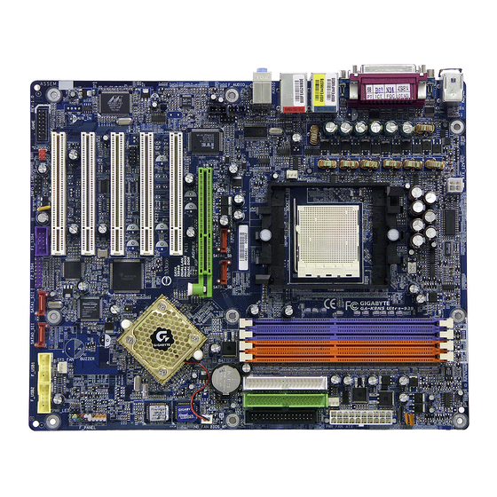
Page 10: Ga-K8Ns Ultra-939 Motherboard Layout
GA-K8NS Ultra-939 Motherboard Layout ATX_12V KB_MS RAM_LED SOCKET 939 CPU_FAN AUDIO ICS1883 F_AUDIO SUR_CEN SATA0_SB SATA1_SB 2X_DET CD_IN nVIDIA ® nForce ™ IT8712 CLR_CMOS Ultra PCI1 BACKUP BIOS CODEC MAIN PCI2 BIOS IR_CIR PCI3 TSB82AA2 Marvell 8001 F_PANEL PCI4 SiI3512... -
Page 11: Block Diagram
Block Diagram AMD K8 AGP Slot CPUCLK+/- (800MHz) 4X/8X Socket 939 AGPCLK (66MHz) DDR400/DDR333/266/200 DIMM HyperTransport Unbuffered DIMMs BIOS IR_CIR LAN1 LAN2 nVIDIA Game Port RJ45 RJ45 LPC BUS nForce Floppy 5 PCI IT8712 Ultra LPT Port Marvell ICS 1883 8001 PS/2 KB/Mouse 24 MHz... - Page 12 GA-K8NS Ultra-939 Motherboard - 12 -...
-
Page 13: Chapter 2 Hardware Installation Process
Chapter 2 Hardware Installation Process To set up your computer, you must complete the following steps: Step 1 - Install the Central Processing Unit (CPU) Step 2 - Install Memory Modules Step 3 - Install Expansion Cards Step 4 - Install I/O Peripherals Cables Step 1 Step 4 Step 2... -
Page 14: Step 1: Install The Central Processing Unit (Cpu)
Pull the lever to the 90-degree directly. Figure 2. Pin 1 location on the Socket and Processor. Move the socket lever to the locked position while holding pressure on the center of the processor. GA-K8NS Ultra-939 Motherboard - 14 -... - Page 15 Step1-2. When the processor is installed in the socket, apply thermal grease to the processor(as shown in Figure 3) prior to installing the heatsink. Phase change materials develop strong adhesive forces between the heatsink and processor. Removing the heatsink under such condi- tions can cause the processor to be removed from the socket without moving the socket lever to the unlocked position and then damage the processor pins or socket contacts.
-
Page 16: Step 2: Install Memory Modules
Then push it down. 3. Close the plastic clip at both edges of the DIMM sockets to lock the DIMM module. Reverse the installation steps when you wish to remove the DIMM module. GA-K8NS Ultra-939 Motherboard - 16 -... - Page 17 When Dual Channel Technology is activated, the bandwidth of memory bus will be double the original one,with the fastest speed at 6.4GB/s(DDR400) or 5.3GB/s(DDR333). GA-K8NS Ultra-939 includes four DIMM slots, and each Channel has 2 DIMMs as following: Channel A : DDR 1, DDR 3...
-
Page 18: Step 3: Install Expansion Cards
When an AGP 2X (3.3V) card is installed the 2X_DET will light up, indicating a non-supported graphics card is inserted. Informing users that system might not boot up normally due to AGP 2X (3.3V) is not supported by the chipset. GA-K8NS Ultra-939 Motherboard - 18 -... -
Page 19: Step 4: Install I/O Peripherals Cables
Step 4: Install I/O Peripherals Cables Step 4-1: I/O Back Panel Introduction PS/2 Keyboard and PS/2 Mouse Connector This connector supports standard PS/2 PS/2 Mouse Connector keyboard and PS/2 mouse. (6 pin Female) PS/2 Keyboard Connector (6 pin Female) Parallel Port, Serial Ports (COMA / COMB) This connector supports 2 standard COM ports Parallel Port (25 pin Female) and 1 Parallel port. - Page 20 If you want to enable 8-channel function you can MIC In refer to page 30, and contact your nearest dealer for optional SUR_CEN cable. If you want the detail information for 2-/4-/6-/8-channel audio setup installation, please refer to page 66. GA-K8NS Ultra-939 Motherboard - 20 -...
-
Page 21: Step 4-2: Connectors Introduction
Step 4-2: Connectors Introduction 1) ATX_12V 14) RAM_LED 2) ATX (Power Connector) 15) 2X_DET 3) CPU_FAN 16) F_AUDIO 4) SYS_FAN 17) SUR_CEN 5) PWR_FAN 18) SPDIF_IO 6) NB_FAN 19) CD_IN 7) FDD 20) F_USB1 / F_USB2 8) IDE1 / IDE2 21) F1_1394 / F2_1394 9) SATA0_SB / SATA1_SB;... - Page 22 Pin No. Definition +12V +12V Pin No. Definition 3.3V 3.3V Power Good 5V SB (stand by +5V) +12V 3.3V -12V PS_ON(soft on/off) GA-K8NS Ultra-939 Motherboard - 22 -...
- Page 23 3/4/5) CPU_FAN / SYS_FAN / PWR_FAN (Cooler Fan Power Connector) The cooler fan power connector supplies a +12V power voltage via a 3-pin power connector and possesses a foolproof connection design. Most coolers are designed with color-coded power connector wires. A red power connector wire indicates a positive connection and requires a +12V power voltage.
- Page 24 If you wish to connect two IDE devices, please set the jumper on one IDE device as Master and the other as Slave (for information on settings, please refer to the instructions located on the IDE device). IDE2 IDE1 GA-K8NS Ultra-939 Motherboard - 24 -...
- Page 25 9/10) SATA0_SB / SATA1_SB; SATA0_SII / SATA1_SII (Serial ATA Connector) Serial ATA can provide 150MB/s transfer rate. Please refer to the BIOS setting for the Serial ATA and install the proper driver in order to work properly. Pin No. Definition SATA0_SB / SATA1_SB SATA0_SII / SATA1_SII The SATA0_SII / SATA1_SII connectors...
- Page 26 Open: Normal Operation (Green) Close: Reset Hardware System PW (Power Switch) Open: Normal Operation (Red) Close: Power On/Off MSG (Message LED/ Power/ Sleep LED) Pin 1: LED anode(+) (Yellow) Pin 2: LED cathode(-) NC (Purple) GA-K8NS Ultra-939 Motherboard - 26 -...
- Page 27 13) PWR_LED PWR_LED is connect with the system power indicator to indicate whether the system is on/off. It will blink when the system enters suspend mode. If you use dual color LED, power LED will turn to another color. Pin No. Definition MPD+ MPD-...
- Page 28 Please note, you can have the alternative of using front audio connector or of using rear audio connector to play sound. Pin No. Definition MIC_BIAS Power Front Audio (R) Rear Audio (R) Reserved No Pin Front Audio (L) Rear Audio (L) GA-K8NS Ultra-939 Motherboard - 28 -...
- Page 29 17) SUR_CEN (Surround Center Connector) Please contact your nearest dealer for optional SUR_CEN cable. Pin No. Definition SUR OUTL SUR OUTR No Pin CENTER_OUT BASS_OUT AUX_L AUX_R 18) SPDIF_IO (SPDIF In / Out Connector) The SPDIF output is capable of providing digital audio to external speakers or compressed AC3 data to an external Dolby Digital Decoder.
- Page 30 For optional front USB cable, please contact your local dealer. Pin No. Definition Power Power USB Dx- USB Dy- USB Dx+ USB Dy+ No Pin GA-K8NS Ultra-939 Motherboard - 30 -...
- Page 31 21) F1_1394 / F2_1394 (Front IEEE1394 Connector) Serial interface standard set by Institute of Electrical and Electronics Engineers, which has features like high speed, highbandwidth and hot plug. Be careful with the polarity of the IEEE1394 connector. Check the pin assignment carefully while you connect the IEEE1394 cable, incorrect connection between the cable and connector will make the device unable to work or even damage it.
- Page 32 This connector allows you to connect some external devices to provide you extra function. Check the pin assignment while you connect the external device cable. Please contact your nearest dealer for optional external device cable. Pin No. Definition SMBCLK SMBDATA GPIO No Pin +12V +12V GA-K8NS Ultra-939 Motherboard - 32 -...
- Page 33 25) CLR_CMOS (Clear CMOS) You may clear the CMOS data to its default values by this jumper. To clear CMOS, temporarily short 1-2 pin. Default doesn't include the "Shunter" to prevent from improper use this jumper. Open: Normal Close: Clear CMOS - 33 - Hardware Installation Process...
- Page 34 GA-K8NS Ultra-939 Motherboard - 34 -...
-
Page 35: Chapter 3 Bios Setup
Chapter 3 BIOS Setup BIOS Setup is an overview of the BIOS Setup Program. The program that allows users to modify the basic system configuration. This type of information is stored in battery-backed CMOS RAM so that it retains the Setup information when the power is turned off. ENTERING SETUP Powering ON the computer and pressing <Del>... -
Page 36: The Main Menu (For Example: Bios Ver. : E1)
This setup page includes all onboard peripherals. Power Management Setup This setup page includes all the items of Green function features. PnP/PCI Configurations This setup page includes all the configurations of PCI & PnP ISA resources. GA-K8NS Ultra-939 Motherboard - 36 -... -
Page 37: Select Language
PC Health Status This setup page is the System auto detect Temperature, voltage, fan, speed. MB Intelligent Tweaker(M.I.T.) This setup page is control CPU's clock and frequency ratio. Top Performance If you wish to maximize the performance of your system, set "Top Performance" as "Enabled". Select Language This setup page is select multi-language. -
Page 38: Standard Cmos Features
Cylinder Number of cylinders Head Number of heads Precomp Write precomp Landing Zone Landing zone Sector Number of sectors If a hard disk has not been installed, select NONE and press <Enter>. GA-K8NS Ultra-939 Motherboard - 38 -... - Page 39 Drive A / Drive B The category identifies the types of floppy disk drive A or drive B that has been installed in the computer. None No floppy drive installed 360K, 5.25" 5.25 inch PC-type standard drive; 360K byte capacity. 1.2M, 5.25"...
-
Page 40: Advanced Bios Features
BIOS can not tell from 720K, 1.2M or 1.44M drive type as they are all 80 tracks. Disabled BIOS will not search for the type of floppy disk drive by track number. Note that there will not be any warning message if the drive installed is 360K. (Default value) GA-K8NS Ultra-939 Motherboard - 40 -... - Page 41 Password Check System The system can not boot and can not access to Setup page will be denied if the correct password is not entered at the prompt. Setup The system will boot, but access to Setup will be denied if the correct password is not entered at the prompt.
-
Page 42: Integrated Peripherals
SATA Primary Master RAID [Disabled] SATA Secndry Master RAID [Disabled] : Move Enter: Select +/-/PU/PD: Value F10: Save ESC: Exit F1: General Help F3: Language F5: Previous Values F6: Fail-Save Defaults F7: Optimized Defaults GA-K8NS Ultra-939 Motherboard - 42 -... - Page 43 IDE RAID Enabled Enable IDE RAID function. Disabled Disable this function. (Default value) IDE Channel 0 Master RAID Enabled Enable 1st master channel IDE RAID function. Disabled Disable this function. (Default value) IDE Channel 0 Slave RAID Enabled Enable 1st slave channel IDE RAID function. Disabled Disable this function.
- Page 44 Parallel Port Mode Using Parallel port as Standard Parallel Port. (Default value) Using Parallel port as Enhanced Parallel Port. Using Parallel port as Extended Capabilities Port. ECP+EPP Using Parallel port as ECP & EPP mode. GA-K8NS Ultra-939 Motherboard - 44 -...
- Page 45 ECP Mode Use DMA Set ECP Mode Use DMA to 3. (Default value) Set ECP Mode Use DMA to 1. Game Port Address Set Game Port Address to 201. (Default value) Set Game Port Address to 209. Disabled Disable this function. Midi Port Address Set Midi Port Address to 300.
-
Page 46: Power Management Setup
Enable alarm function to POWER ON system. If RTC Alarm Lead To Power On is Enabled. Day of Month Alarm : Everyday, 1~31 Time (hh: mm: ss) Alarm : (0~23) : (0~59) : (0~59) GA-K8NS Ultra-939 Motherboard - 46 -... - Page 47 Power On by Mouse Disabled Disabled this function. (Default value) Double Click Double click on PS/2 mouse left button to power on system. Power On by Keyboard Disabled Disabled this function. (Default value) Password Enter from 1 to 5 characters to set the keyboard power on password. Keyboard 98 If there is a "POWER"...
-
Page 48: Pnp/Pci Configurations
Auto assign IRQ to PCI 1/5. (Default value) 3,4,5,7,9,10,11,12,14,15 Set IRQ 3,4,5,7,9,10,11,12,14,15 to PCI 1/PCI5. PCI 2 IRQ Assignment Auto Auto assign IRQ to PCI 2. (Default value) 3,4,5,7,9,10,11,12,14,15 Set IRQ 3,4,5,7,9,10,11,12,14,15 to PCI 2. GA-K8NS Ultra-939 Motherboard - 48 -... -
Page 49: Pc Health Status
PC Health Status CMOS Setup Utility-Copyright (C) 1984-2004 Award Software PC Health Status Vcore Item Help DDR25V Menu Level +3.3V +12V Current CPU Temperature 51°C Current CPU FAN Speed 3125 RPM Current POWER FAN Speed 0 RPM Current SYSTEM FAN Speed 0 RPM CPU Warning Temperature [Disabled]... -
Page 50: Mb Intelligent Tweaker(M.i.t.)
Increase HT-Link voltage +0.1V. +0.2v Increase HT-Link voltage +0.2V. +0.3v Increase HT-Link voltage +0.3V. DDR voltage control Normal Supply DDR voltage as DDR required. (Default value) +0.1v Increase DDR voltage +0.1V. +0.2v Increase DDR voltage +0.2V. GA-K8NS Ultra-939 Motherboard - 50 -... -
Page 51: Top Performance
Top Performance CMOS Setup Utility-Copyright (C) 1984-2004 Award Software Standard CMOS Features Top Performance Advanced BIOS Features Select Language Integrated Peripherals Load Optimized Defaults Top Performance Power Management Setup Set Supervisor Password Disabled......[ ] PnP/PCI Configurations Set User Password Enabled......[ ] PC Health Status Save &... -
Page 52: Load Optimized Defaults
Setup Menu. If you select "Setup" at "Password Check" in Advance BIOS Features Menu, you will be prompted only when you try to enter Setup. GA-K8NS Ultra-939 Motherboard - 52 -... -
Page 53: Exit Without Saving
Save & Exit Setup CMOS Setup Utility-Copyright (C) 1984-2004 Award Software Standard CMOS Features Top Performance Advanced BIOS Features Select Language Integrated Peripherals Load Optimized Defaults Power Management Setup Set Supervisor Password Save to CMOS and EXIT (Y/N)? Y PnP/PCI Configurations Set User Password PC Health Status Save &... - Page 54 GA-K8NS Ultra-939 Motherboard - 54 -...
-
Page 55: Chapter 4 Technical Reference
Certainly, you wonder why motherboard vendors could not just do something right to save your time and effort and save you from the lousy BIOS updating work? Here it comes! Now Gigabyte announces @BIOS - - the first Windows BIOS live update utility. This is a smart BIOS update software. It could help you to download the BIOS from internetand update it. -
Page 56: Flash Bios Method Introduction
Save Settings to CMOS Q-Flash Utility Update Main BIOS from Floppy Update Backup BIOS from Floppy Save Main BIOS to Floppy Save Backup BIOS to Floppy PgDn/PgUp: Modify : Move ESC: Reset F10: Power Off GA-K8NS Ultra-939 Motherboard - 56 -... - Page 57 3.) Dual BIOS Item explanation: • Wide Range Protection: Disable(Default), Enable Status 1: If any failure (ex. Update ESCD failure, checksum error or reset…) occurs in the Main BIOS, just before the Operating System is loaded and after the power is on, and that the Wide Range Protection is set to "Enable", the PC will boot from Backup BIOS automatically.
- Page 58 TAB: Switch To name the file. Congratulate you have accomplished the saving. CONTROL KEYS <PgDn/PgUp> Make changes < > Move to previous item < > Move to next item <Enter> <Esc> Reset <F10> Power Off GA-K8NS Ultra-939 Motherboard - 58 -...
- Page 59 What's DualBIOS ™ On GIGABYTE motherboards with DualBIOS there are physically two BIOS chips. For simplicity we'll call one your "Main BIOS" and the other we'll call your "Backup BIOS" (your "hot spare"). If your Main BIOS fails, the Backup BIOS almost automatically takes over on your next system boot.
- Page 60 . Another advantage you gain from Giga-Byte's DualBIOS technology is the ability to upgrade from ™ GA-K8NS Ultra-939 Motherboard - 60 -...
- Page 61 Method 2 : @BIOS Utility ™ If you don't have DOS boot disk, we recommend that you used Gigabyte @BIOS ™ program to flash BIOS. Press here. 2. Click Start/ Programs/ GIGABYTE/ @BIOS. 1. Click "@BIOS" item. Click here 3.Click " "...
- Page 62 In method II, be sure that motherboard's model name in BIOS unzip file are the same as your motherboard's. Otherwise, your system won't boot. c. In method I, if the BIOS file you need cannot be found in @BIOS server, please go onto Gigabyte's web ™ site for downloading and updating it according to method II.
-
Page 63: 4- / 6- / 8- Channel Audio Function Introduction
2- / 4- / 6- / 8- Channel Audio Function Introduction The installation of windows 98SE/2K/ME/XP is very simple. Please follow next step to install the function! Stereo Speakers Connection and Settings: We recommend that you use the speaker with amplifier to acquire the best sound effect if the stereo output is applied. - Page 64 Click the icon to select the function. STEP 3 : Click "Speaker Configuration" and select the "UAJ Function". Then click on the left selection bar and select "4CH Speaker" to complete 4 channel audio configuration. GA-K8NS Ultra-939 Motherboard - 64 -...
- Page 65 6 Channel Analog Audio Output Mode Use the back audio panel to connect the audio output without any additional module. STEP 1 : Connect the front channels to "Line Out",the rear Line In channels to "Line In", and the Center/Subwoofer chan- nels to "MIC In".
- Page 66 Surround-Kit "REAR R/L" port. Connect the center/subwoofer channels to the Surround-Kit "SUB CENTER" and the R/L channels to the Sur- round-Kit "SUR BACK" port. GA-K8NS Ultra-939 Motherboard - 66 -...
- Page 67 Method 2: Connect the front channels to the "LINE OUT" port located on the audio panel and the rear channels to the "LINE IN" port. Connect the center/subwoofer channels to the "MIC IN" port located on the audio panel and the R/L channels to the Surround-Kit "SUR BACK"...
- Page 68 Fiber 1. Connect the SPDIF output device to the rear bracket of PC, and fix it with screw. 2. Connect SPDIF device to the motherboard. 3. Connect SPDIF to the SPDIF decoder. GA-K8NS Ultra-939 Motherboard - 68 -...
-
Page 69: Jack-Sensing And Uaj Introduction
Jack-Sensing and UAJ Introduction Jack-Sensing provides audio connectors error-detection function. Install Microsoft DirectX8.1 or later version before to enable Jack-Sensing support for Windows 98/ 98SE/2000/ME. Jack-Sensing includes 2 parts: AUTO and MANUAL. Following is an example for 2 channels (Windows XP): Introduction of audio connectors You may connect CDROM, Walkman or others audio input devices to Line In jack, speakers, earphone or... -
Page 70: Uaj Introduction
(Line-in/ Line-out). That means users do not need to worry the audio device should be plug in Line-in or Line-out jack, the device will work perfectly after UAJ is activated. Enable UAJ function: You can click "UAJ Automatic" button to enable UAJ function. GA-K8NS Ultra-939 Motherboard - 70 -... -
Page 71: Xpress Recovery Introduction
Verifying DMI Pool Data Boot from CD: Boot from CD: Xpress Recovery V1.0 (C) Copy Right 2003. GIGABYTE Technology CO. , Ltd. 1. Execute Backup Utility 2. Execute Restore Utility 3. Remove Backup Image 4. Set Password 5. - Page 72 F9 For Xpress Recovery Press DEL to enter SETUP / Q-Flash, F9 For Xpress Recovery 08/16/2002-I845GE-6A69YG01C-00 Xpress Recovery V1.0 (C) Copy Right 2003. GIGABYTE Technology CO. , Ltd. 1. Execute Backup Utility 2. Execute Restore Utility 3. Remove Backup Image 4.
- Page 73 1. Execute Backup Utility: Press B to Backup your System or Esc to Exit The backup utility will automatically scan your system and back up data as a backup image in your hard drive. Not all systems support access to Xpress Recovery by pressing the F9 key during computer power on.
-
Page 74: Serial Ata Bios Setting Utility Introduction
Spanning stores data onto a drive until it is full, then proceeds to store files onto the next drive in the array. When any disk member fails, the failure affects the entire array. JBOD is not really a RAID and does not support fault tolerance. GA-K8NS Ultra-939 Motherboard - 74 -... - Page 75 6) Complete RAID utility installation. More information on steps 4 and 5 is provided. (For more detailed setup information, please visit our website at http:\\www.gigabyte.com.tw) Configuring the NVIDIA RAID BIOS The NVRAID BIOS setup lets you choose the RAID array type and which hard drives you want to make part of the array.
- Page 76 Clear disk data ? Disk Model Name Disk Model Name 1.0.M ST3120026AS 1.1.M ST3120026AS [ ] Add [Y] YES [N] NO [ ] Del [F6] Back [F7] Finish [TAB] Navigate [ ] Select [ENTER] Popup GA-K8NS Ultra-939 Motherboard - 76 -...
- Page 77 Press Y if you want to wipe out all the data from the RAID array, otherwise press N. You must choose Yes if the drives were previously used as RAID drives. The Array List window appears, where you can review the RAID arrays that you have set up. You can select a disk array as boot device if you want to boot operating system from an array.
- Page 78 (Each time you add a new hard drive to a RAID array, the RAID driver will have to be installed under Windows once for that hard drive. After that, the driver will not have to be installed.) Note: In the menu list, IAA_RAID is Intel ICH5R chipset. GA-K8NS Ultra-939 Motherboard - 78 -...
- Page 79 - 79 - Technical Reference...
- Page 80 GA-K8NS Ultra-939 Motherboard - 80 -...
-
Page 81: Chapter 5 Appendix
Revision History Chapter 5 Appendix Install Drivers Pictures below are shown in Windows XP Insert the driver CD-title that came with your motherboard into your CD-ROM drive, the driver CD-title will auto start and show the installation guide. If not, please double click the CD-ROM device icon in "My computer", and execute the setup.exe. - Page 82 Pack. After install Windows Service Pack, it will show a question mark "?" in "Universal Serial Bus controller" under "Device Manager". Please remove the question mark and restart the system (System will auto-detect the right USB2.0 driver). GA-K8NS Ultra-939 Motherboard - 82 -...
-
Page 83: Software Application
SOFTWARE APPLICATION This page reveals the value-added software developed by Gigabyte and its worldwide partners. Gigabyte Windows Utilities Manager (GWUM) This utility can integrate the Gigabyte's applications in the system tray. Gigabyte Management Tool (GMT) A useful tool which can manage the computer via the network. -
Page 84: Software Information
This page list the contects of softwares and drivers in this CD title. HARDWARE INFORMATION This page lists all device you have for this motherboard. CONTACT US Please see the last page for details. GA-K8NS Ultra-939 Motherboard - 84 -... - Page 85 Below is a collection of general asked questions. To check general asked questions based on a specific motherboard model, please log on to http://tw.giga-byte.com/faq/faq.htm Question 1: I cannot see some options that were included in previous BIOS after updating BIOS. Why? Answer: Some advanced options are hidden in new BIOS version.
- Page 86 Question 8: How do I disable onboard VGA card in order to add an external VGA card? Answer: Gigabyte motherboards will auto-detect the external VGA card after it is plugged in, so you don't need to change any setting manually to disable the onboard VGA.
-
Page 87: Troubleshooting
Troubleshooting If you encounter any trouble during boot up, please follow the troubleshooting procedures. START Turn off the power and unplug the AC power cable, then remove all of the add-on cards and cables from motherboard. Please isolate Please make sure motherboard & chassis are not short ? the short pin. - Page 88 If the above procedure unable to solve your problem, please contact with your local retailer or national distributor for help. Or, you could submit your question to the service mail via Gigabyte website technical support zone (http://www.gigabyte.com.tw). The appropriate response will be provided ASAP.
- Page 89 Technical Support/RMA Sheet Customer/Country: Company: Phone No.: Contact Person: E-mail Add. : Model name/Lot Number: PCB revision: BIOS version: O.S./A.S.: Hardware Mfs. Model name Size: Driver/Utility: Configuration Memory Brand Video Card Audio Card CD-ROM / DVD-ROM Modem Network AMR / CNR Keyboard Mouse Power supply...
- Page 90 ESCD Extended System Configuration Data Error Checking and Correcting Electromagnetic Compatibility Enhanced Parallel Port Electrostatic Discharge Floppy Disk Device Front Side Bus Hard Disk Device Integrated Dual Channel Enhanced Interrupt Request to be continued..GA-K8NS Ultra-939 Motherboard - 90 -...
- Page 91 Acronyms Meaning IOAPIC Input Output Advanced Programmable Input Controller Industry Standard Architecture Local Area Network Input / Output Logical Block Addressing Light Emitting Diode Megahertz MIDI Musical Instrument Digital Interface Memory Translator Hub Memory Protocol Translator Network Interface Card Operating System Original Equipment Manufacturer PCI A.G.P.
- Page 92 GA-K8NS Ultra-939 Motherboard - 92 -...
- Page 93 - 93 - Appendix...
- Page 94 GA-K8NS Ultra-939 Motherboard - 94 -...
- Page 95 Contact Us Taiwan (Headquarters) Japan GIGA-BYTE TECHNOLOGY CO., LTD. NIPPON GIGA-BYTE CORPORATION Address: No.6, Bau Chiang Road, Hsin-Tien, Taipei Hsien, WEB address : http://www.gigabyte.co.jp Taiwan. Singapore TEL: +886 (2) 8912-4888 GIGA-BYTE SINGAPORE PTE. LTD. FAX: +886 (2) 8912-4003 Tech. Support : Tech.
- Page 96 China Australia NINGBO G.B.T. TECH. TRADING CO., LTD. GIGABYTE TECHNOLOGY PTY. LTD. Tech. Support : Address: 3/6 Garden Road, Clayton, VIC 3168 Australia http://cn.giga-byte.com/TechSupport/ServiceCenter.htm TEL: +61 3 85616288 Non-Tech. Support(Sales/Marketing) : FAX: +61 3 85616222 http://ggts.gigabyte.com.tw/nontech.asp Tech. Support : WEB address : http://www.gigabyte.com.cn http://www.giga-byte.com.au/TechSupport/ServiceCenter.htm...
Need help?
Do you have a question about the GA-K8NS Ultra-939 and is the answer not in the manual?
Questions and answers