Table of Contents
Advertisement
Quick Links
GA-G31MX-S2
LGA775 socket motherboard for Intel
Intel
Pentium
®
®
User's Manual
Rev. 1002
12ME-G31MXS2-1002R
* The WEEE marking on the product indicates this product must not be disposed of with user's other household waste
and must be handed over to a designated collection point for the recycling of waste electrical and electronic equipment!!
* The WEEE marking applies only in European Union's member states.
processor family/Intel
Core
processor family/
®
TM
Celeron
processor family
®
®
Advertisement
Table of Contents

Related Manuals for Gigabyte GA-G31MX-S2


Summary of Contents for Gigabyte GA-G31MX-S2
- Page 1 GA-G31MX-S2 LGA775 socket motherboard for Intel Core processor family/ ® Intel Pentium processor family/Intel Celeron processor family ® ® ® ® User's Manual Rev. 1002 12ME-G31MXS2-1002R * The WEEE marking on the product indicates this product must not be disposed of with user's other household waste and must be handed over to a designated collection point for the recycling of waste electrical and electronic equipment!! * The WEEE marking applies only in European Union's member states.
-
Page 3: Identifying Your Motherboard Revision
GIGABYTE's prior written permission. Documentation Classifications In order to assist in the use of this product, GIGABYTE provides the following types of documentations: For detailed product information, carefully read the User's Manual. For instructions on how to use GIGABYTE's unique features, read or download the information on/from the Support\Motherboard\Technology Guide page on our website. -
Page 4: Table Of Contents
Table of Contents Box Contents ......................... 6 Optional Items ......................... 6 GA-G31MX-S2 Motherboard Layout ................7 Block Diagram ........................ 8 Chapter 1 Hardware Installation ..................9 Installation Precautions ..................9 Product Specifications ..................10 Installing the CPU and CPU Cooler .............. 13 1-3-1 Installing the CPU .................... - Page 5 Chapter 3 Drivers Installation ..................55 Installing Chipset Drivers ................55 Software Applications ..................56 Driver CD Information ..................56 Hardware Information ..................57 Contact Us ..................... 57 Chapter 4 Unique Features ..................59 Xpress Recovery2 ..................59 BIOS Update Utilities ..................64 4-2-1 Updating the BIOS with the Q-Flash Utility ............
-
Page 6: Box Contents
Box Contents GA-G31MX-S2 motherboard Motherboard driver disk User's Manual Intel LGA775 CPU Installation Guide ® One IDE cable and one floppy disk drive cable Two SATA 3Gb/s cables I/O Shield The box contents above are for reference only and the actual items shall depend on product package you obtain. -
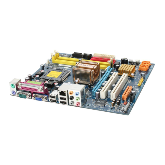
Page 7: Ga-G31Mx-S2 Motherboard Layout
GA-G31MX-S2 Motherboard Layout KB_MS CPU_FAN LGA775 ATX_12V R_USB BATTERY CLR_CMOS Intel ® SYS_FAN AUDIO F_AUDIO PCIE_16 PCI1 RTL8110SC Intel ICH7 ® PCI2 PCIE_4 SATAII0 SATAII2 CODEC MBIOS SPDIF_IO SATAII1 SATAII3 F_USB1 F_USB2 CD_IN - 7 -... -
Page 8: Block Diagram
Block Diagram CPU CLK+/- (333/266/200 MHz) LGA775 PCIe CLK Processor (100 MHz) D-Sub Host Interface DDR2 800/667 MHz Dual Channel Memory Intel ® PCI Express x16 GMCH CLK (333/266/200 MHz) 1 PCI Express x4 BIOS PCIe CLK (100 MHz) ATA-100/66/33 IDE Channel Intel ®... -
Page 9: Chapter 1 Hardware Installation
Chapter 1 Hardware Installation Installation Precautions The motherboard contains numerous delicate electronic circuits and components which can become damaged as a result of electrostatic discharge (ESD). Prior to installation, carefully read the user's manual and follow these procedures: Prior to installation, do not remove or break motherboard S/N (Serial Number) sticker or •... -
Page 10: Product Specifications
® ® Intel Celeron processor in the LGA 775 package ® ® (Go to GIGABYTE's website for the latest CPU support list.) Support for Intel Hyper-Threading Technology ® L2 cache varies with CPU Front Side Bus 1333/1066/800 MHz FSB Chipset... - Page 11 Internal Connectors 1 x 24-pin ATX main power connector 1 x 4-pin ATX 12V power connector 1 x floppy disk drive connector 1 x IDE connector 4 x SATA 3Gb/s connectors 1 x CPU fan header 1 x system fan header 1 x front panel header 1 x front panel audio header 1 x CD In connector...
- Page 12 Windows Vista/XP/2000 ® ® (Go to GIGABYTE's website for operating system support information.) Form Factor Micro ATX form factor; 24.4cm x 21.5cm (Note 1) Based on standard PC architecture, a certain amount of memory is reserved for system usage and therefore the actual memory size is less than the stated amount. For example, 4 GB of memory size will instead be shown as 3.xx GB during system startup.
-
Page 13: Installing The Cpu And Cpu Cooler
Read the following guidelines before you begin to install the CPU: • Make sure that the motherboard supports the CPU. (Go to GIGABYTE's website for the latest CPU support list.) • Always turn off the computer and unplug the power cord from the power outlet before installing the CPU to prevent hardware damage. - Page 14 CPU notches with the socket alignment keys) and gently insert the CPU into position. Step 5: Once the CPU is properly inserted, replace the load plate and push the CPU socket lever back into its locked position. GA-G31MX-S2 Motherboard - 14 -...
-
Page 15: Installing The Cpu Cooler
1-3-2 Installing the CPU Cooler Follow the steps below to correctly install the CPU cooler on the motherboard. (The following procedure uses Intel boxed cooler as the example cooler.) ® Male Push Pin Direction of the Arrow Sign on the Male The Top Push Pin of Female... -
Page 16: Installing The Memory
• Make sure that the motherboard supports the memory. It is recommended that memory of the same capacity, brand, speed, and chips be used. (Go to GIGABYTE's website for the latest memory support list.) • Always turn off the computer and unplug the power cord from the power outlet before installing the memory to prevent hardware damage. -
Page 17: Installing A Memory
1-4-2 Installing a Memory Before installing a memory module , make sure to turn off the computer and unplug the power cord from the power outlet to prevent damage to the memory module. DDR2 DIMMs are not compatible to DDR DIMMs. Be sure to install DDR2 DIMMs on this motherboard. -
Page 18: Installing An Expansion Card
PCI Ex- press x16 slot. • Removing the Card: Press the white latch at the end of the PCI Express x16 slot to release the card and then pull the card straight up from the slot. GA-G31MX-S2 Motherboard - 18 -... -
Page 19: Back Panel Connectors
Back Panel Connectors PS/2 Keyboard and PS/2 Mouse Port Use the upper port (green) to connect a PS/2 mouse and the lower port (purple) to connect a PS/2 keyboard. Parallel Port Use the parallel port to connect devices such as a printer, scanner and etc. The parallel port is also called a printer port. - Page 20 Only microphones still MUST be connected to the default Mic in jack ( ). Refer to the instructions on setting up a 2/4/5.1/ 7.1-channel audio configuration in Chapter 5, "Configuring 2/4/5.1/7.1-Channel Audio." GA-G31MX-S2 Motherboard - 20 -...
-
Page 21: Internal Connectors
Internal Connectors ATX_12V BATTERY ATX (Power Connector) F_PANEL CPU_FAN F_AUDIO SYS_FAN CD_IN SPDIF_IO F_USB1 / F_USB2 SATAII0 / 1 / 2 / 3 CLR_CMOS PWR_LED Read the following guidelines before connecting external devices: • First make sure your devices are compliant with the connectors you wish to connect. •... - Page 22 Pin No. Definition 3.3V 3.3V 3.3V -12V PS_ON(soft On/Off) Power Good 5V SB(stand by +5V) +12V +12V (Only for 2x12-pin ATX) +5V (Only for 2x12-pin ATX) 3.3V (Only for 2x12-pin ATX) GND (Only for 2x12-pin ATX) GA-G31MX-S2 Motherboard - 22 -...
- Page 23 3/4) CPU_FAN/SYS_FAN (Fan Headers) The motherboard has a 4-pin CPU fan header (CPU_FAN) and a 3-pin system fan header (SYS_FAN). Each fan header supplies a +12V power voltage and possesses a foolproof insertion design. When connecting a fan cable, be sure to connect it in the correct orientation. Most fans are designed with color-coded power connector wires.
- Page 24 7) SATAII0/1/2/3 (SATA 3Gb/s Connectors, Controlled by ICH7) The SATA connectors conform to SATA 3Gb/s standard and are compatible with SATA 1.5Gb/s standard. Each SATA connector supports a single SATA device. Pin No. Definition SATAII0 SATAII2 SATAII1 SATAII3 GA-G31MX-S2 Motherboard - 24 -...
-
Page 25: Battery
8) PWR_LED (System Power LED Header) This header can be used to connect a system power LED on the chassis to indicate system power status. The LED is on when the system is operating. The LED keeps blinking when the system is in S1 sleep state. -
Page 26: F_Panel
LED, hard drive activity LED, speaker and etc. When connecting your chassis front panel module to this header, make sure the wire assign- ments and the pin assignments are matched correctly. GA-G31MX-S2 Motherboard - 26 -... -
Page 27: Front Panel Audio Header
11) F_AUDIO (Front Panel Audio Header) The front panel audio header supports Intel High Definition audio (HD) and AC'97 audio. You may connect your chassis front panel audio module to this header. Make sure the wire assignments of the module connector match the pin assignments of the motherboard header. Incorrect connection between the module connector and the motherboard header will make the device unable to work or even damage it. - Page 28 • Do not plug the IEEE 1394 bracket (2x5-pin) cable into the USB header. • Prior to installing the USB bracket, be sure to turn off your computer and unplug the power cord from the power outlet to prevent damage to the USB bracket. GA-G31MX-S2 Motherboard - 28 -...
-
Page 29: Chassis Intrusion Header
15) CLR_CMOS (Clearing CMOS Jumper) Use this jumper to clear the CMOS values (e.g. date information and BIOS configurations) and reset the CMOS values to factory defaults. To clear the CMOS values, place a jumper cap on the two pins to temporarily short the two pins or use a metal object like a screwdriver to touch the two pins for a few seconds. - Page 30 GA-G31MX-S2 Motherboard - 30 -...
-
Page 31: Chapter 2 Bios Setup
To see more advanced BIOS Setup menu options, you can press <Ctrl> + <F1> in the main menu of the BIOS Setup program. To upgrade the BIOS, use either the GIGABYTE Q-Flash or @BIOS utility. Q-Flash allows the user to quickly and easily upgrade or back up BIOS without entering the •... -
Page 32: Startup Screen
BIOS Setup settings. You can access Boot Menu again to change the first boot device setting as needed. <End> : Q-Flash Press the <End> key to access the Q-Flash utility directly without having to enter BIOS Setup first. GA-G31MX-S2 Motherboard - 32 -... -
Page 33: The Main Menu
The Main Menu Once you enter the BIOS Setup program, the Main Menu (as shown below) appears on the screen. Use arrow keys to move among the items and press <Enter> to accept or enter a sub-menu. (Sample BIOS Version: F1a) CMOS Setup Utility-Copyright (C) 1984-2007 Award Software Standard CMOS Features Load Fail-Safe Defaults... - Page 34 (Pressing <F10> can also carry out this task.) Exit Without Saving Abandon all changes and the previous settings remain in effect. Pressing <Y> to the confirmation message will exit BIOS Setup. (Pressing <Esc> can also carry out this task.) GA-G31MX-S2 Motherboard - 34 -...
-
Page 35: Standard Cmos Features
Standard CMOS Features CMOS Setup Utility-Copyright (C) 1984-2007 Award Software Standard CMOS Features Date (mm:dd:yy) Thu, Jun 28 2007 Item Help Time (hh:mm:ss) 10:31:24 Menu Level IDE Channel 0 Master [None] IDE Channel 0 Slave [None] IDE Channel 2 Master [None] IDE Channel 2 Slave [None]... - Page 36 Base Memory Also called conventional memory. Typically, 640 KB will be reserved for the MS-DOS operating system. Extended Memory The amount of extended memory. Total Memory The total amount of memory installed on the system. GA-G31MX-S2 Motherboard - 36 -...
-
Page 37: Advanced Bios Features
Advanced BIOS Features CMOS Setup Utility-Copyright (C) 1984-2007 Award Software Advanced BIOS Features Hard Disk Boot Priority [Press Enter] Item Help First Boot Device [Floppy] Menu Level Second Boot Device [Hard Disk] Third Boot Device [CDROM] Password Check [Setup] HDD S.M.A.R.T. Capability [Disabled] CPU Hyper-Threading [Enabled]... - Page 38 Sets PCI Express x4 graphics card as the first display. (Note) This item is present only if you install a CPU that supports this feature. For more information about Intel CPUs' unique features, please visit Intel's website. GA-G31MX-S2 Motherboard - 38 -...
- Page 39 Onboard VGA Enables or disables the onboard VGA function. Enable If No Ext PEG Activates the onboard VGA only if no PCI Express VGA card is installed. (Default) Always Enable Always activates the onboard VGA, whether or not a PCI Express card is installed. If you wish to set up a dual view configuration, set this item to Always Enable.
-
Page 40: Integrated Peripherals
This value is dependent on the On-Chip SATA Mode and PATA IDE Set to settings. When PATA IDE Set to is configured to Ch. 1 Master/Slave, this option will be automatically set to Ch. 0 Master/Slave. GA-G31MX-S2 Motherboard - 40 -... - Page 41 SATA Port 1/3 Set to This value is dependent on the On-Chip SATA Mode and PATA IDE Set to settings. When PATA IDE Set to is configured to Ch. 0 Master/Slave, this option will be automatically set to Ch. 1 Master/Slave. USB Controller Enables or disables the integrated USB controller.
- Page 42 Options are: 378/IRQ7 (default), 278/IRQ5, 3BC/IRQ7, Disabled. Parallel Port Mode Selects an operating mode for the onboard parallel (LPT) port. Options are: SPP (Standard Parallel Port)(default), EPP (Enhanced Parallel Port), ECP (Extended Capabilities Port), ECP+EPP. GA-G31MX-S2 Motherboard - 42 -...
-
Page 43: Power Management Setup
Power Management Setup CMOS Setup Utility-Copyright (C) 1984-2007 Award Software Power Management Setup ACPI Suspend Type [S3(STR)] Item Help Soft-Off by PWR-BTTN [Instant-Off] Menu Level PME Event Wake Up [Enabled] Power On by Ring [Enabled] Resume by Alarm [Disabled] x Date (of Month) Alarm Everyday x Time (hh:mm:ss) Alarm 0 : 0 : 0... - Page 44 The system is turned on upon the return of the AC power. Memory The system returns to its last known awake state upon the return of the AC power. (Note) Supported on Windows Vista operating system only. ® ® GA-G31MX-S2 Motherboard - 44 -...
-
Page 45: Pnp/Pci Configurations
PnP/PCI Configurations CMOS Setup Utility-Copyright (C) 1984-2007 Award Software PnP/PCI Configurations PCI1 IRQ Assignment [Auto] Item Help PCI2 IRQ Assignment [Auto] Menu Level : Move Enter: Select +/-/PU/PD: Value F10: Save ESC: Exit F1: General Help F5: Previous Values F6: Fail-Safe Defaults F7: Optimized Defaults PCI1 IRQ Assignment Auto... -
Page 46: Pc Health Status
F, 90 C/194 CPU/SYSTEM FAN Fail Warning Allows the system to emit warning sound if the CPU/system fan is not connected or fails. Check the fan condition or fan connection when this occurs. (Default: Disabled) GA-G31MX-S2 Motherboard - 46 -... - Page 47 CPU Smart FAN Control Enables or disables the CPU fan speed control function. Enabled allows the CPU fan to run at different speed according to the CPU temperature. You can adjust the fan speed with EasyTune based on system requirements. If disabled, CPU fan runs at full speed. (Default: Enabled) CPU Smart FAN Mode Specifies how to control CPU fan speed.
-
Page 48: Mb Intelligent Tweaker(M.i.t.)
20 seconds to allow for automated system reboot, or clear the CMOS values to reset the board to default values. (Default: Disabled) (Note) This item appears only if you install a CPU that supports this feature. GA-G31MX-S2 Motherboard - 48 -... - Page 49 CPU Host Frequency (Mhz) Allows you to manually set the CPU host frequency. This item is configurable only if the CPU Host Clock Control option is enabled. For an 800 MHz FSB CPU, set this item to 200 MHz. For a 1066 MHz FSB CPU, set this item to 266 MHz. For a 1333 MHz FSB CPU, set this item to 333 MHz.
- Page 50 CPU being installed. (Default: Normal) Note: Increasing CPU voltage may result in damage to your CPU or reduce the useful life of the CPU. Normal CPU Vcore Displays the normal operating voltage of your CPU. GA-G31MX-S2 Motherboard - 50 -...
-
Page 51: Load Fail-Safe Defaults
2-10 Load Fail-Safe Defaults CMOS Setup Utility-Copyright (C) 1984-2007 Award Software Standard CMOS Features Load Fail-Safe Defaults Advanced BIOS Features Load Optimized Defaults Integrated Peripherals Set Supervisor Password Power Management Setup Set User Password Load Fail-Safe Defaults (Y/N)? N PnP/PCI Configurations Save &... -
Page 52: Set Supervisor/User Password
BIOS settings but not to make changes. To clear the password, press <Enter> on the password item and when requested for the password, press <Enter> again. The message "PASSWORD DISABLED" will appear, indicating the password has been cancelled. GA-G31MX-S2 Motherboard - 52 -... -
Page 53: Save & Exit Setup
2-13 Save & Exit Setup CMOS Setup Utility-Copyright (C) 1984-2007 Award Software Standard CMOS Features Load Fail-Safe Defaults Advanced BIOS Features Load Optimized Defaults Integrated Peripherals Set Supervisor Password Save to CMOS and EXIT (Y/N)? Y Power Management Setup Set User Password PnP/PCI Configurations Save &... - Page 54 GA-G31MX-S2 Motherboard - 54 -...
-
Page 55: Chapter 3 Drivers Installation
Chapter 3 Drivers Installation • Before installing the drivers, first install the operating system. (The following instructions use Windows XP as the example operating system.) • After installing the operating system, insert the motherboard driver disk into your optional drive. The driver Autorun screen is automatically displayed which looks like that shown in the screen shot below. -
Page 56: Software Applications
Software Applications This page displays all the tools and applications that GIGABYTE develops and some free software. You may press the Install button following an item to install it. Driver CD Information This page provides information about the drivers, applications and tools in this driver disk. -
Page 57: Hardware Information
Hardware Information This page provides information about the hardware devices on this motherboard. Contact Us Check the contacts information of the GIGABYTE headquarter in Taiwan and the overseas branch offices on the last page of this manual. - 57 -... - Page 58 GA-G31MX-S2 Motherboard - 58 -...
-
Page 59: Chapter 4 Unique Features
Chapter 4 Unique Features Xpress Recovery2 Xpress Recovery2 is an utility that allows you to quickly compress and back up your system data and perform restoration of it. Supporting NTFS, FAT32, and FAT16 file systems, Xpress Recovery2 can back up data on PATA and SATA hard drives and restore it. Before You Begin: •... - Page 60 Recovery2 (10 GB or more is recommended; actual size requirements vary, depending on the amount of data) (Figure 2). Figure 2 Figure 1 3. Select a file system (for example, NTFS) and begin the installation of the operating system (Figure 3). Figure 3 GA-G31MX-S2 Motherboard - 60 -...
- Page 61 4. After the operating system is installed, right-click the My Computer icon on your desktop and select Manage (Figure 4). Go to Computer Management to check disk allocation. Xpress Recovery2 will save the backup file to the unallocated space (black stripe along the top)(Figure 5). Please note that if there is no enough unallocated space, Xpress Recovery2 cannot save the backup file.
- Page 62 Xpress Recovery2 will begin the backup process (Figure 11). Figure 10 Figure 11 3. When finished, go to Disk Management to check disk allocation. Xpress Recovery2 will automatically create a new partition to store the backup image file. Figure 12 GA-G31MX-S2 Motherboard - 62 -...
- Page 63 D. Using the Restore Function in Xpress Recovery2 Select RESTORE to restore the backup to your hard drive in case the system breaks down. The RESTORE option will not be present if no backup is created before (Figure 13, 14). Figure 13 Figure 14 E.
-
Page 64: Bios Update Utilities
4-2-1 Updating the BIOS with the Q-Flash Utility A. Before You Begin: 1. From GIGABYTE's website, download the latest compressed BIOS update file that matches your motherboard model. 2. Extract the file and save the new BIOS file (e.g. g31mxs2.f1) to your floppy disk, USB flash drive, or hard drive. - Page 65 B. Updating the BIOS When updating the BIOS, choose the location where the BIOS file is saved. The follow procedure assumes that you save the BIOS file to a floppy disk. Step 1: 1. Insert the floppy disk containing the BIOS file into the floppy disk drive. In the main menu of Q- Flash, use the up or down arrow key to select Update BIOS from Drive and press <Enter>.
- Page 66 Load Optimized Defaults Press <Y> to load BIOS defaults Step 6: Select Save & Exit Setup and then press <Y> to save settings to CMOS and exit BIOS Setup. The procedure is complete after the system restarts. GA-G31MX-S2 Motherboard - 66 -...
-
Page 67: Updating The Bios With The @Bios Utility
BIOS or a system that is unable to start. 4. Do not use the C.O.M. (Corporate Online Management) function when using @BIOS. 5. GIGABYTE product warranty does not cover any BIOS damage or system failure resulting from an inadequate BIOS flashing. - Page 68 • If the BIOS update file for your motherboard is not present on the @BIOS server site, please manually download the BIOS update file from GIGABYTE's website and follow the instructions in "Update the BIOS without Using the Internet Update Function" below.
-
Page 69: Easytune 5
Toggles between Easy and Advance Mode Display Field Displays panel of CPU frequency Function LEDs Shows the information of the current function GIGABYTE Logo Visits GIGABYTE website Help Displays EasyTune 5 help screen Exit or Minimize Quits or minimizes EasyTune Incorrectly doing overclock/overvoltage may result in damage to CPU, chipset, or memory and reduce the useful life of these components. -
Page 70: Windows Vista Readyboost
• The USB flash drive must have at least 256 MB of space. • The recommended amount of memory to use for ReadyBoost acceleration is one to three times the amount of RAM installed in your computer. GA-G31MX-S2 Motherboard - 70 -... -
Page 71: Chapter 5 Appendix
Chapter 5 Appendix Configuring Audio Input and Output 5-1-1 Configuring 2/4/5.1/7.1-Channel Audio The motherboard provides six audio jacks on the back panel which support 2/4/5.1/7.1-channel audio. The picture to the right shows the default audio jack Center/Subwoofer Line In Speaker Out assignments. - Page 72 Step 3: Everytime you connect an audio device to an audio jack, the Connected device box appears. Select the device according to the type of device you connect. Then click OK to complete the configuration. GA-G31MX-S2 Motherboard - 72 -...
- Page 73 B. Configuring Sound Effect: You may configure an audio environment on the Sound Effect tab. C. Configuring AC'97 Audio: If you want to connect an AC'97 front panel audio module, click the tool icon on the Audio I/O tab On the Global Connector Settings box, select the Dis- able front panel jack detection check box.
-
Page 74: Installing The S/Pdif In And Out Cable (Optional)
A. Installing the S/PDIF In and Out Cable: Step 1: First, attach the connector at the end of the cable to the SPDIF_IO header on your motherboard. Step 2: Secure the metal bracket to the chassis back panel with a screw. GA-G31MX-S2 Motherboard - 74 -... - Page 75 Step 3: Connect a S/PDIF coaxial cable or a S/PDIF optical cable (either one) to an external decoder for transmitting the S/PDIF digital audio signals. S/PDIF Coaxial Cable S/PDIF Optical Cable B. Configuring S/PDIF out: Click the tool icon in the DIGITAL section. In the S/PDIF In/Out Settings dialog box, select an out- put sampling rate and select (or disable) the output source.
-
Page 76: Configuring Microphone Recording
Note: The microphone functions on the front panel and back panel cannot be used at the same time. Step 3: Locate the Volume icon in your system tray and click it to open the volume control panel GA-G31MX-S2 Motherboard - 76 -... - Page 77 Step 4: To hear the sound being recorded during the record- ing process when using the microphone function on the front panel, do not select the Mute check box under Front Pink In or Front Green In in Master Volume. It is recommended that you set the volume at a middle level.
-
Page 78: Using The Sound Recorder
3. To play a sound file, click the Play button 4. To stop playing, click the Stop button 5. You may use the Fast Forward button move to the beginning of a file or the Fast Back- ward button to the end. GA-G31MX-S2 Motherboard - 78 -... -
Page 79: Troubleshooting
5-2-1 Frequently Asked Questions To read more FAQs for your motherboard, please go to the Support\Motherboard\FAQ page on GIGABYTE's website. Q: In the BIOS Setup program, why are some BIOS options missing? A: Some advanced options are hidden in the BIOS Setup program. Press <Delete> to enter BIOS Setup during the POST. -
Page 80: Troubleshooting Procedure
Turn on the power to start the computer. Press <Delete> to enter BIOS Setup. Select "Load Fail-Safe Defaults" (or "Load Optimized Defaults"). Select "Save & Exit Setup" to save changes and exit BIOS Setup. (Continued...) GA-G31MX-S2 Motherboard - 80 -... - Page 81 The power supply, When the computer is turned on, is the CPU cooler running? CPU or CPU socket might fail. The problem is verified and solved. The graphics card, expansion slot, or Check if there is display on your monitor. monitor might fail.
- Page 82 GA-G31MX-S2 Motherboard - 82 -...
- Page 83 - 83 - Appendix...
- Page 84 GA-G31MX-S2 Motherboard - 84 -...
- Page 85 - 85 - Appendix...
- Page 86 Contact Us Taiwan (Headquarters) China GIGA-BYTE TECHNOLOGY CO., LTD. NINGBO G.B.T. TECH. TRADING CO., LTD. Address: No.6, Bau Chiang Road, Hsin-Tien, WEB address : http://www.gigabyte.cn Taipei 231, Taiwan Shanghai TEL: +886-2-8912-4888 TEL: +86-21-63410999 FAX: +886-2-8912-4003 FAX: +86-21-63410100 Tech. and Non-Tech. Support (Sales/Marketing) : Beijing http://ggts.gigabyte.com.tw...
- Page 87 Czech Republic WEB address : http://www.gigabyte.co.yu Representative Office Of GIGA-BYTE Technology Co., Ltd. You may go to the GIGABYTE website, select your language in CZECH REPUBLIC in the language list on the top right corner of the website. WEB address : http://www.gigabyte.cz Turkey Representative Office Of GIGA-BYTE Technology Co., Ltd.
- Page 88 - 88 -...
Need help?
Do you have a question about the GA-G31MX-S2 and is the answer not in the manual?
Questions and answers