
Related Manuals for ABB ZX2


Summary of Contents for ABB ZX2
- Page 1 M A N UA L FO R I N S TA L L AT I O N A N D O P E R AT I O N H B 6 4 4/0 6 E N ZX2 Version for ANSI markets...
- Page 3 • Only install the switchgear in enclosed rooms suitable for electrical equipment. With the aim of a smooth installation sequence and ensuring a high quality standard, have installation at site performed by specially trained personnel or managed and supervised by the ABB Service Department.
-
Page 4: Table Of Contents
TA B L E O F C O N T E N T S — Table of contents — 1. Standards, regulations, notes, 3.3.5. Installation of the top-mounted further documents 6 – 10 box for the busbar metering system with isolating device —... - Page 5 TA B L E O F C O N T E N T S — — 5. Operation 67-90 6. Test procedures 91-97 5.1. General notes 6.1. Testing for the off-circuit condition 5.2. Line side grounding and grounding 6.1.1. LRM system of system sections 6.1.2.
-
Page 6: Standards, Regulations, Notes, Further Documents
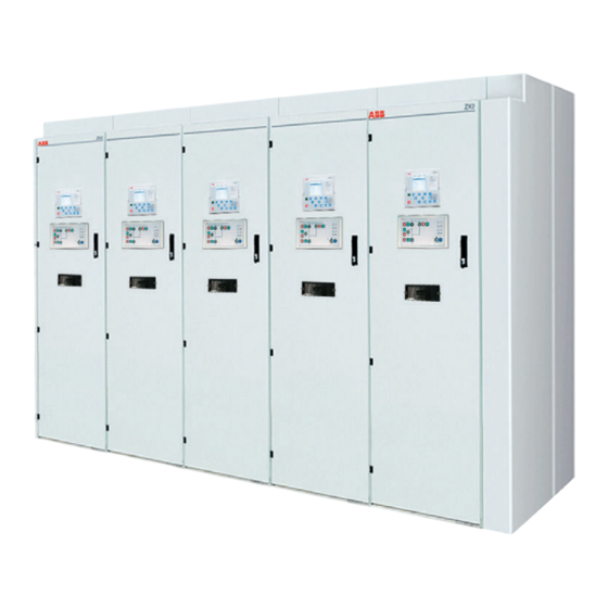
Z X 2 G A S - I N S U L AT E D M E D I U M V O LTA G E S W I TC H G E A R You have chosen a gas-insulated switchgear of series ZX2. This switchgear from the ZX range is notable for the following features: •... - Page 7 1 . S TA N D A R D S , R E G U L AT I O N S , N OT E S , F U R T H E R D O C U M E N T S Table 1.3: Relevant IEEE standards and regulations IEEE Guide for the Application of Gas-Insulated Substations C37.122.2...
- Page 8 Z X 2 G A S - I N S U L AT E D M E D I U M V O LTA G E S W I TC H G E A R Fundamental notes on this manual: Read the relevant sections of this manual through in full before performing work, so as to ensure correct handling.
- Page 9 - Construction data if compiled specifically for this order - Circuit diagrams - Grounding diagram - switchgear ground to station ground (not part of ABB supply) • Instruction manuals - Use of SF insulating gas HB 645 en - Circuit-breaker VD4X, type 1 according to Fig.
- Page 10 Z X 2 G A S - I N S U L AT E D M E D I U M V O LTA G E S W I TC H G E A R — Fig. 1.3: Feeder panel, 1200 A, Double busbar, example configuration 1.13...
-
Page 11: Despatch And Storage
2 . D E S PATC H A N D S TO R A G E — 2. Despatch and storage 2.1. Conditions on delivery 2.3. Packaging The panels have been routine tested to The panels have been prepared for transport by IEC 62271-200. -
Page 12: Handling By Fork Lift Truck
Z X 2 G A S - I N S U L AT E D M E D I U M V O LTA G E S W I TC H G E A R — 2.4.1. Handling by fork lift truck Handling without a pallet Fig. -
Page 13: Handling By Trolley Jack
2.4.3.2 b to the lifting lugs using shackles. Thread the lifting ropes through the cut-outs in the rope guides. The lifting ropes and shackles are not included in the ABB scope of supply. Rope guide (1 x left, 1 x right) - Page 14 Z X 2 G A S - I N S U L AT E D M E D I U M V O LTA G E S W I TC H G E A R — Fig. 2.4.3.1 b: Single busbar at the front Double busbar or single busbar Fastening diagram at the rear...
-
Page 15: Handling By Hydraulic Lift Trolley
2 . D E S PATC H A N D S TO R A G E — 2.4.4. Handling by hydraulic lift trolley 2.5. Intermediate storage Fig. 2.4.4.1: • Fasten a hydraulic lift trolley of suitable • Store the panels in the upright position. Handling by hydraulic lift trolley capacity to each of the front and rear of the... -
Page 16: Installation Of The Switchgear At Site
Z X 2 G A S - I N S U L AT E D M E D I U M V O LTA G E S W I TC H G E A R — 3. Installation of the switchgear at site 3.1. - Page 17 3 . I N S TA L L AT I O N O F T H E S W I TC H G E A R AT S I T E — Cleaning of soiled silicone insulating parts • Silicone insulating parts on the busbar Fig.
-
Page 18: Handling Sulphur Hexafluoride
Consult the order documents for the position of the foundation bars in the switchgear room. Important note If no standard ABB foundation frames are used, observe the relevant construction and laying Assemble the components immediately drawings for the special frames. - Page 19 3 . I N S TA L L AT I O N O F T H E S W I TC H G E A R AT S I T E — inserted slot rods to slide into the sections of one screw with dished washer for each...
- Page 20 Z X 2 G A S - I N S U L AT E D M E D I U M V O LTA G E S W I TC H G E A R — • Align the foundation frame vertically as When voltage transformers are used in the cable Fig.
-
Page 21: Reinforced Foundation Frames, Type
3 . I N S TA L L AT I O N O F T H E S W I TC H G E A R AT S I T E — 3.2.1.2. Reinforced foundation frames, type 2 four screws , taking account of any deviation Fig. - Page 22 Z X 2 G A S - I N S U L AT E D M E D I U M V O LTA G E S W I TC H G E A R — • Fix the welded angles of the foundation frames Fig.
-
Page 23: Special Considerations With A Raised False Floor
3 . I N S TA L L AT I O N O F T H E S W I TC H G E A R AT S I T E — 3.2.2. Special considerations with the raised Fig.3.2.2.1: false floor Plan view of a supporting beam for the switchgear when a... -
Page 24: Assembly Of The Switchgear
Z X 2 G A S - I N S U L AT E D M E D I U M V O LTA G E S W I TC H G E A R — 3.3. Assembly of the switchgear Fig. -
Page 25: Greasing The Floor Bars
Fig. 3.3.2.1 a: When a standard foundation frame supplied by • Screw two guide pins to each of the upper Fitting guide pins ABB is used, remove the protective film. Grease brackets of the busbar compartments on the — Fig.3.3.2.1 b:... - Page 26 Z X 2 G A S - I N S U L AT E D M E D I U M V O LTA G E S W I TC H G E A R — Fastening the panels to foundation frames When the standard foundation frame made of Fig.
- Page 27 3 . I N S TA L L AT I O N O F T H E S W I TC H G E A R AT S I T E — Fig. 3.3.2.2 b: Fastening the panel to the foundation frame made of aluminum profiles Slot in the foundation frame section...
- Page 28 Z X 2 G A S - I N S U L AT E D M E D I U M V O LTA G E S W I TC H G E A R — Fastening the panels to reinforced foundation and the baseframe of the panel (Fig.
- Page 29 3 . I N S TA L L AT I O N O F T H E S W I TC H G E A R AT S I T E — Fig. 3.3.2.3 c: Fastening the panels to Base frame of the panel reinforced foundation frames in sectional view Cheese head screw M 10 x 25...
- Page 30 Z X 2 G A S - I N S U L AT E D M E D I U M V O LTA G E S W I TC H G E A R — Fig. 3.3.2.5: Fitted contact tubes Important note Important note and silicone insulating...
- Page 31 3 . I N S TA L L AT I O N O F T H E S W I TC H G E A R AT S I T E — • Connect the brackets on the adjacent busbar Fig.
- Page 32 Z X 2 G A S - I N S U L AT E D M E D I U M V O LTA G E S W I TC H G E A R — Fig. 3.3.2.9: Panel joints for double busbar panel —...
- Page 33 Cheese head screw, M 8 x 40 Fig. 3.3.2.11 Nut, M 8 2 x dished washer, 8 (see fig. 2.3.2.8) Cheese head screw, M 10 x 50 Nut, M 10 2 x dished washer 10 (see fig. 2.3.2.7) — Abb. 3.3.2.12...
- Page 34 Z X 2 G A S - I N S U L AT E D M E D I U M V O LTA G E S W I TC H G E A R — • Lead the control wiring for the panel-panel Fig.
-
Page 35: Closure Of Busbar Sockets
3 . I N S TA L L AT I O N O F T H E S W I TC H G E A R AT S I T E — 3.3.3. Closure of busbar sockets • Treat the busbar sockets and the insulating Fig. -
Page 36: Installation Of The Heat Sinks
Z X 2 G A S - I N S U L AT E D M E D I U M V O LTA G E S W I TC H G E A R — 3.3.4. Installation of the heat sinks •... -
Page 37: Installation Of The Top-Mounted Box For The Busbar Metering System With Isolating Device
3 . I N S TA L L AT I O N O F T H E S W I TC H G E A R AT S I T E — • Align the bores in the flange plate so that they Installation of the top-mounted box Fig. - Page 38 Z X 2 G A S - I N S U L AT E D M E D I U M V O LTA G E S W I TC H G E A R — Fig. 3.3.5.2: Installation of the top-mounted box Top-mounted box Drying agent bag...
- Page 39 3 . I N S TA L L AT I O N O F T H E S W I TC H G E A R AT S I T E Installation of the connecting conductors (see fig. 3.3.5.3): • The upper flat conductors for connection of the voltage transformer sockets are fixed in a transport position at the works.
- Page 40 Z X 2 G A S - I N S U L AT E D M E D I U M V O LTA G E S W I TC H G E A R — Fig. 3.3.5.3: Installation of the connecting conduc- tors (simplified) Voltage transformer socket...
-
Page 41: Installation Of The Plenums And
3 . I N S TA L L AT I O N O F T H E S W I TC H G E A R AT S I T E — 3.3.6. Installation of the plenums and end covers Fig. -
Page 42: Transformers (Metering 1)
Z X 2 G A S - I N S U L AT E D M E D I U M V O LTA G E S W I TC H G E A R — 3.3.7.1 Dismantling of voltage transformers •... - Page 43 3 . I N S TA L L AT I O N O F T H E S W I TC H G E A R AT S I T E — • Crank the assembly aid up to the stop •...
-
Page 44: Installation Of Voltage Transformers (Metering 1)
Z X 2 G A S - I N S U L AT E D M E D I U M V O LTA G E S W I TC H G E A R — 3.3.7.2. Installation of voltage transformers •... - Page 45 3 . I N S TA L L AT I O N O F T H E S W I TC H G E A R AT S I T E — • First crank the voltage transformer up by a few •...
-
Page 46: Installation Of Voltage Transformers (Metering 2)
Z X 2 G A S - I N S U L AT E D M E D I U M V O LTA G E S W I TC H G E A R 3.3.7.3. Installation of voltage transformers (metering 2) Hazard warning If the switchgear is in operation:... - Page 47 3 . I N S TA L L AT I O N O F T H E S W I TC H G E A R AT S I T E — Voltage transformers for operating voltages pins to the stud bolts on the enclosure (tighten- Fig.
- Page 48 Z X 2 G A S - I N S U L AT E D M E D I U M V O LTA G E S W I TC H G E A R — Voltage transformers for operating voltages up Fig.
- Page 49 3 . I N S TA L L AT I O N O F T H E S W I TC H G E A R AT S I T E — • Fasten the transformer cover to the previously Fig.
- Page 50 Z X 2 G A S - I N S U L AT E D M E D I U M V O LTA G E S W I TC H G E A R — Installation of the casing (fig. 3.3.7.3.7) Fig.
-
Page 51: Dismantling Of Voltage Transformers (Metering 2)
3 . I N S TA L L AT I O N O F T H E S W I TC H G E A R AT S I T E 3.3.7.4. Dismantling of voltage transformers (metering 2) Hazard warning If the switchgear is in operation: •... -
Page 52: Installation Of Voltage Transformers (Metering 3)
Z X 2 G A S - I N S U L AT E D M E D I U M V O LTA G E S W I TC H G E A R — • Remove the protective caps from the silicone 3.3.7.5. - Page 53 3 . I N S TA L L AT I O N O F T H E S W I TC H G E A R AT S I T E — • Screw the hexagonal pins to the stud bolts on Fig.
- Page 54 Z X 2 G A S - I N S U L AT E D M E D I U M V O LTA G E S W I TC H G E A R — Installation of the casing (fig. 3.3.7.5.4) •...
-
Page 55: Wiring Of Voltage Transformers
3 . I N S TA L L AT I O N O F T H E S W I TC H G E A R AT S I T E — 3.3.7.6. Wiring of voltage transformers Fig. 3.3.7.6.1: The voltage transformers are fitted with terminal Possible terminal board configurations boards. - Page 56 Z X 2 G A S - I N S U L AT E D M E D I U M V O LTA G E S W I TC H G E A R — Grounding of terminals on the voltage trans- Fig.
- Page 57 3 . I N S TA L L AT I O N O F T H E S W I TC H G E A R AT S I T E — Grounding of open delta windings Fig.3.3.7.6.3: If the open delta windings of the voltage trans- Grounding of the circuit in the low formers are damped with a resistor, the windings...
- Page 58 Z X 2 G A S - I N S U L AT E D M E D I U M V O LTA G E S W I TC H G E A R — Fig. 3.3.7.6.5: View of the terminal Hazard warning board of a voltage trans- former with open delta...
- Page 59 3 . I N S TA L L AT I O N O F T H E S W I TC H G E A R AT S I T E Checking the wiring Hazard warning Finally, check the grounding system of the voltage transformer wiring in accordance with table 3.3.7.6.2.
-
Page 60: Installation Of Damping Resistors
Z X 2 G A S - I N S U L AT E D M E D I U M V O LTA G E S W I TC H G E A R — 3.3.7.7. Installation of damping resistors Fig. - Page 61 3 . I N S TA L L AT I O N O F T H E S W I TC H G E A R AT S I T E — Fig. 3.3.7.7.1b: Position of damp- Resistors ing resistors —...
-
Page 62: Connecting The Main Groundingbar
• Details of the cross section and the number of Important note connections can be found in the grounding dia- gram (not included in ABB’s scope of supply). Check the cable sockets and/or the outer cones for damage. If there is damage to 3.5. -
Page 63: Fitting Surge Arresters
3 . I N S TA L L AT I O N O F T H E S W I TC H G E A R AT S I T E — • Remove the cover of the cable termination 3.6. -
Page 64: Fitting Blanking Plugs
Z X 2 G A S - I N S U L AT E D M E D I U M V O LTA G E S W I TC H G E A R — 3.7. Fitting blanking plugs 3.9. -
Page 65: Commissioning
4 . C O M M I S S I O N I N G — 4. Commissioning 4.1. Conditions for commissioning of the • The following accessories have been handed switchgear over to the operators: The conditions for commissioning of the - This manual switchgear are as follows: - The corresponding documents and order... -
Page 66: Energizing The System
Z X 2 G A S - I N S U L AT E D M E D I U M V O LTA G E S W I TC H G E A R 4.2. Energizing the system Switchgear with double busbar •... -
Page 67: Operation
5 . O P E R AT I O N — 5. Operation • Please consult the order documents for the con- Hazard warning ditions of further internal electrical interlocks in the panels (e.g. disconnect – disconnect inter- • All activities in connection with locks in double busbar systems) and panel to operation of the switchgear require panel electrical interlocks. -
Page 68: Line Side Grounding And Grounding Of System Sections
Z X 2 G A S - I N S U L AT E D M E D I U M V O LTA G E S W I TC H G E A R 5.2. Line side grounding and grounding of system sections —... -
Page 69: Line Side Grounding Of Panels In Single Busbar Systems
5 . O P E R AT I O N — 5.2.1. Line side grounding of panels in single busbar systems Fig. 5.2.1.1: Line side ground- Observe the following single line diagrams for ing, single bus grounding the line side of a feeder panel. —... -
Page 70: Grounding The Busbar
Z X 2 G A S - I N S U L AT E D M E D I U M V O LTA G E S W I TC H G E A R 5.2.3. Grounding the busbar — Fig. - Page 71 5 . O P E R AT I O N — Fig. 5.2.3.1.3: Closing the ground- ing switch (busbar 2) in the bus tie — Fig. 5.2.3.1.4: Closing the cir- cuit-breaker in the bus tie: Busbar 1 grounded BB1 (front) BB2 (rear) —...
-
Page 72: Grounding The Busbar Via
Z X 2 G A S - I N S U L AT E D M E D I U M V O LTA G E S W I TC H G E A R — 5.2.3.2. Grounding the busbar via grounding and •... - Page 73 5 . O P E R AT I O N — Procedure for panels with outer cones Fig. 5.2.3.2.3: (Fig. 5.2.3.2.3) Connection of an grounding and short- The three-pole grounding and short-circuiting Outer cone circuiting device to of the panel Current-carrying device is connected via manufacturer- and a feeder panel with...
-
Page 74: Non-Interrupting Bus Transfer
Z X 2 G A S - I N S U L AT E D M E D I U M V O LTA G E S W I TC H G E A R — 5.3. Non-interrupting bus transfer Fig. - Page 75 5 . O P E R AT I O N — =J01 Fig. 5.3.2: Closing the bus tie BB1 (front) BB2 (rear) — Fig. 5.3.3: Closing the dis- connect -QBD — Fig. 5.3.4: Opening the dis- connect -QZD — Fig. 5.3.5: Opening the bus tie —...
-
Page 76: Electrical Operation
Z X 2 G A S - I N S U L AT E D M E D I U M V O LTA G E S W I TC H G E A R 5.4. Electrical operation — Fig.5.4.1: In normal cases, all switches are operated Conventional control Hazard warning... -
Page 77: Emergency Manual Operation
Please contact Electrical protection against the ABB Service Department if required. maloperation is then ineffective. Prior to emergency manual operation, ) for the motorized switch the mcbs (... - Page 78 Z X 2 G A S - I N S U L AT E D M E D I U M V O LTA G E S W I TC H G E A R — Fig. 5.5.1.1: Control side of the circuit-breaker oper- ating mechanism —...
-
Page 79: Emergency Manual Operation Of The Three-Position Disconnect And The Disconnect
5 . O P E R AT I O N 5.5.2. Emergency manual operation of the three- — position disconnect and the disconnect Fig. 5.5.2.1: Operator control area of the three position dis- Operator control area of the three-position connect mechanism with the access lock closed disconnect mechanism The operator control area of the three position... - Page 80 Z X 2 G A S - I N S U L AT E D M E D I U M V O LTA G E S W I TC H G E A R Conditions for operations — • A crank is required for manual operation of the Fig.
- Page 81 Deblocking of the blocking magnet requires work on the operating mechanism and may only be performed by qualified personnel. Please contact the ABB Service Department if required.
-
Page 82: View Ports
Z X 2 G A S - I N S U L AT E D M E D I U M V O LTA G E S W I TC H G E A R — To open the view port cover, move the bolt 5.6. -
Page 83: Switch Position Grounding Switch Closed
5 . O P E R AT I O N — 5.6.2. Switch position OPEN 5.6.1. Switch position grounding Fig. 5.6.1.1: switch CLOSED Switch position ground- The sliding contact is in the central part of the ing switch CLOSED The red mark on the moving contact must be disconnect, such that the face surface of the —... -
Page 84: Switch Position Disconnect Switch Closed
Z X 2 G A S - I N S U L AT E D M E D I U M V O LTA G E S W I TC H G E A R — 5.6.3. Switch position disconnect Fig. -
Page 85: Gas Monitoring With Density Sensors
5 . O P E R AT I O N — 5.7. Gas monitoring with density sensors 5.8. Operation of the isolating device for voltage Fig. 5.8.1: The high voltage compartments must have a transformers Position of the controls for the sufficient insulating gas pressure during The voltage transformers in the metering panel, voltage transformer... -
Page 86: Operation Of The Isolating Device For Voltage Transformers In Metering Panels
Z X 2 G A S - I N S U L AT E D M E D I U M V O LTA G E S W I TC H G E A R — 5.8.1. Operation of the isolating device for Grounding the voltage transformers Fig. -
Page 87: Operation Of The Isolating Device For Voltage Transformers In Panels With Outer Cones
5 . O P E R AT I O N — 5.8.2. Operation of the isolating device for The operating mechanism for the voltage Fig. 5.8.2.1: voltage transformers in panels with outer cones transformer isolating device is located in the Controls and displays for the voltage trans- cable termination compartment on the right-... - Page 88 Z X 2 G A S - I N S U L AT E D M E D I U M V O LTA G E S W I TC H G E A R — Grounding the voltage transformers Connecting the voltage transformers Fig.
-
Page 89: Operation Of The Isolating Device For Integrated Metering
5 . O P E R AT I O N Grounding the voltage transformers (fig. 5.8.3.1) 5.8.3. Operation of the isolating device for integrated metering • Pull lever down in the direction of the arrow and move it to the right. Allow the lever to engage in the limit position. - Page 90 Z X 2 G A S - I N S U L AT E D M E D I U M V O LTA G E S W I TC H G E A R — Fig. 5.8.3.1: Voltage transformer isolating device for the integrated metering system...
-
Page 91: Test Procedures
6 . T E S T P R O C E D U R E S — 6. Test procedures — 6.1. Testing for the off-circuit condition Fig. 6.1.1: The off-circuit condition on the cable side is LRM system with display unit tested by means of the capacitive voltage indicator (pick-off on the outer cone). -
Page 92: Testing For The In-Phase Condition
Z X 2 G A S - I N S U L AT E D M E D I U M V O LTA G E S W I TC H G E A R 6.2. Testing for the in-phase condition Testing for the in-phase condition, e.g. -
Page 93: Voltage Test Of The Main Circuit
6 . T E S T P R O C E D U R E S — 6.3.2. Voltage test of the main circuit Fig. 6.3.2.1: Voltage test in case of a Important notes sectionalizer (without circuit-breaker) Important note • If there are busbar metering panels within the system section to be tested, In the course of testing, the test voltage isolate the relevant voltage... - Page 94 Z X 2 G A S - I N S U L AT E D M E D I U M V O LTA G E S W I TC H G E A R Test sequence • Connect the test transformer to the test plug or test cable and ground the other two phases of the main circuit.
-
Page 95: Secondary Protection Testing
6 . T E S T P R O C E D U R E S 6.4. Secondary protection testing Hazard warning Comply with the safety regulations to EN 50110. • Isolate the feeder panel to be tested in accordance with section 5. •... -
Page 96: Protection Testing By Primary Current Injection
Z X 2 G A S - I N S U L AT E D M E D I U M V O LTA G E S W I TC H G E A R — 6.5. Protection testing by primary current •... -
Page 97: Partial Discharge Test
6 . T E S T P R O C E D U R E S 6.6. Partial discharge test The measurement of partial discharges is a suitable means of detecting certain defects in the equipment under test and is a useful complement to the dielectric tests. -
Page 98: Service
Z X 2 G A S - I N S U L AT E D M E D I U M V O LTA G E S W I TC H G E A R — 7. Service — 7.1. Inspection and maintenance of the 7.4. -
Page 99: Actions At The End Of The Service Life
ABB can be appointed to decommission and dismantle the switchgear. The switchgear is then professionally dismantled by ABB and the SF which is normally reusable, removed before the switchgear is broken down into its remaining components. -
Page 100: List Of Tools
9. List of tools The tools required for assembly of the switchgear system are detailed in the list below. Tools are not part of the ABB scope of supply. All the tools listed must comply with the safety Lifting ropes, 1.5 m, regulations of the country concerned. -
Page 101: Working Materials, Auxiliary Materials And Accessories
Gas cylinders are not normally part of the ABB scope of supply. In the case of airfreight, the gas compartments of the panels are filled at the works to a reduced in-... -
Page 102: Accessories
Z X 2 G A S - I N S U L AT E D M E D I U M V O LTA G E S W I TC H G E A R 10.3. Accessories ABB part number ABB part number... -
Page 103: Technical Data
1 1 . T E C H N I C A L D ATA — 11. Technical data The technical data of the switchgear can be found on the name plate. The name plate of the panel is located at the top on the right-hand side wall of the opened low voltage compartment. - Page 104 Z X 2 G A S - I N S U L AT E D M E D I U M V O LTA G E S W I TC H G E A R — Table 11.2: Operating conditions 104 (+40) Ambient temperature, maximum ( °F (°C)
- Page 105 1 1 . T E C H N I C A L D ATA — Fig. 11.1 Double feeder panel, 600 A, (with outer 1.13 cone), single busbar, example configuration — Fig. 11.2 Outgoing feeder panel, 1200 A, double busbar, example configuration 1.12 1.13...
- Page 106 Z X 2 G A S - I N S U L AT E D M E D I U M V O LTA G E S W I TC H G E A R — Fig. 11.3 Feeder panel 2400 A, double busbar, example configuration 1.13...
-
Page 107: Disclaimer
(i) has been improperly repaired or altered; (ii) has been subjected to misuse, negligence or accident; (iii) has been used in a manner contrary to ABB’s written in- structions; (iv) is comprised of materials provided by or a design specified by Purchaser;... - Page 108 Z X 2 G A S - I N S U L AT E D M E D I U M V O LTA G E S W I TC H G E A R...
- Page 109 1 2 . D I S C L A I M E R — Notes...
- Page 110 We reserve the right to make technical changes or modify the contents of this document without prior notice. With regard to purchase orders, the agreed particulars shall prevail. ABB AG does not accept any responsibility whatsoever for potential errors or possible lack of information in this document.
- Page 111 1 2 . D I S C L A I M E R...
- Page 112 — ABB AG Oberhausener Str. 33 D-40472 Ratingen Germany abb.com/medium-voltage/en © Copyright 2018 ABB. All rights reserved. Specifications subject to change without notice.
Need help?
Do you have a question about the ZX2 and is the answer not in the manual?
Questions and answers