Advertisement
Available languages
Available languages
Quick Links
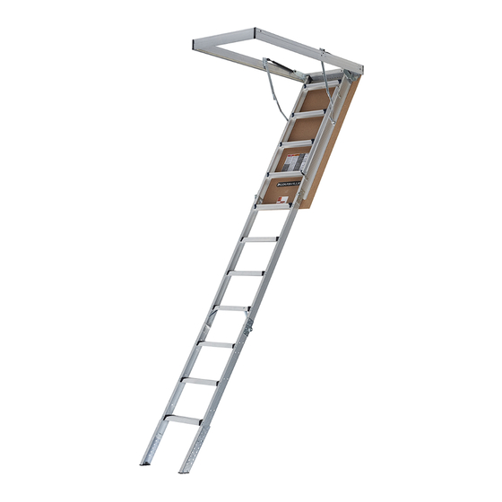
ALUMINUM
ATTIC LADDER
WITH NEW ALUMINUM FRAME
INSTALLATION INSTRUCTIONS
INSTRUCCIONES DE INSTALACIÓN DE LA
ESCALERA DE ÁTICO DE ALUMINIO CON NUEVO MARCO DE ALUMINIO
MODELS / MODELOS:
AL2240MG, AP2240MG, AH2240MG-R5, AF2240MG-R5, AL2540MG, AP2540MG,
AH2540MG-R5, AF2540MG-R5, AL2540MG-R10, AC2540MG-R10, AL3040MG-R10,
ENGLISH / INGLES: Page 1 / Página 1 | SPANISH / ESPAÑOL: Page 20 / Pagina 20
Advertisement

Related Manuals for Louisville Ladder AL2240MG


Summary of Contents for Louisville Ladder AL2240MG
- Page 1 ESCALERA DE ÁTICO DE ALUMINIO CON NUEVO MARCO DE ALUMINIO MODELS / MODELOS: AL2240MG, AP2240MG, AH2240MG-R5, AF2240MG-R5, AL2540MG, AP2540MG, AH2540MG-R5, AF2540MG-R5, AL2540MG-R10, AC2540MG-R10, AL3040MG-R10, ENGLISH / INGLES: Page 1 / Página 1 | SPANISH / ESPAÑOL: Page 20 / Pagina 20...
-
Page 2: Important Safety Considerations
To prevent accidents, read all instructions completely before beginning this installation. Improper installation could result in SERIOUS BODILY INJURY OR DEATH. Inspect the attic ladder for shipping damage and missing parts: Check wooden door panel for splits and warpage. ... - Page 3 8. Verify that the attic ladder meets local building codes, including fire separation requirements. 9. If the house has roof trusses, do not cut the trusses (ceiling joists) without consulting an engineer for approval. 10. Before installation, read all the instruction labels on the attic ladder shown in Figure 1. 11.
- Page 4 Included with your attic ladder: AL2240MG, AP2240MG, AH2240MG-R5, ALUMINUM SERIES AF2240MG-R5, AL2540MG, AP2540MG, (Kits inside the box) AH2540MG-R5, AF2540MG-R5, AL2540MG-R10, AC2540MG-R10, AL3040MG-R10,AC3040MG-R10 ITEM Metal Straps 14" Pull Cord Washer 1/4" x 1" Plastic Bushings Screw Philips #10 3/8" Lag Screws 3"...
- Page 5 Rough Ceiling HT. Landing Swing Clearance Inside Step Width Model Opening Range "A" Space "B" "C" "D" AL2240MG AP2240MG 22 1/2" X 54" 11 7/8" AH2240MG-R5 AF2240MG-R5 AL2540MG AP2540MG 7´8" -10´3" 67" 74" AH2540MG-R5 25 1/2" X 54" 14 7/8"...
- Page 6 STEP 1: PRELIMINARY INSTALLATION INSTRUCTIONS Installation requires TWO PEOPLE at all times, as installation will block the attic door for an extended period of time while one installer is in the attic. Installers must stay in verbal contact with each other. DO NOT INSTALL DURING EXTREME HEAT.
- Page 7 Materials needed: C. Carefully unfold the 14” metal straps, these could have sharp edges. Place a #10 3/8” Philips screw through the bottom ¼” diameter (large) strap hole. Position a metal strap against the side of aluminum frame over the predrilled hole as shown in Figure 4 Figure 5 Figure 7...
- Page 8 Materials needed (Not Included): F. Attach temporary supports boards “A” and “B” (1” x 4” x 32”) with 2-1/2” wood screws (not included). Support “A” will be 3” from the rough opening at the header/hinge end. Support “B” will be 8” from the rough opening at footer end. Be sure to follow these board placement dimensions so the temporary support boards do not hinder the remaining installation steps.
- Page 9 NOTE: Installer #2 will be unable to exit the attic until the installation is complete. Be sure installer #2 has all the materials and tools needed to complete the tasks to be performed from above. Be sure there is electricity or sufficient battery power for the duration of the installation for lighting and power tools. Before work, assess the area to be sure your workplace is safe (overhead hazards, floor support, heat, etc.) Material needed in the attic: G.
- Page 10 12 : IGURE SHIMMING THE FOOTER K. Before continuing, Installer #1 must measure the diagonals of the aluminum frame to ensure the attic is square. Diagonal Figure 13 measurements A1 and A2 should match within 1/8”. See . If not, your attic ladder door may not close properly. If measurements do not match, adjust the attic ladder moving the footer end side-to-side.
- Page 11 NEVER USE DECK OR SHEETROCK SCREWS IN PLACE OF THE LAG SCREWS PROVIDED. Deck or sheetrock (drywall) screws are not suitable for supporting attic ladder loads. DO NOT CLIMB ON THE ATTIC LADDER SECTIONS. Standing or climbing on the attic ladder´s climbing sections prior to adjusting the ladder length and installing the adjustable shoes (STEP 5) could result in a fall and cause SERIOUS BODILY INJURY OR DEATH.
- Page 12 SECTION N) IGURE ALTERNATIVE INSTALLATION SEE NOTE ON Figure 19 O. Installer #1: Remove the temporary wood support boards “A” and “B” from the ceiling. See 19 : IGURE REMOVING TEMPORARY SUPPORT BOARDS P. Installer #2 Make sure no materials are stored on the attic ladder door as these may fall when opening the door. Installer #1 and #2: Carefully open the attic ladder door and make sure the spreader bars are fully extended to avoid unexpected door closure.
- Page 13 R. Installer #1 Open and close the attic ladder door several times to ensure it is centered in the frame and does not bind. The Figure 21 door should fully seat within the frame recess (See ). If the door is NOT centered and it binds or overhangs onto the frame, additional adjustments will be needed.
- Page 14 STEP 4: FINALIZING THE ATTIC LADDER INSTALLATION DO NOT CLIMB ON THE ATTIC LADDER SECTIONS. Standing or climbing on the attic ladder´s climbing section prior to adjusting the ladder length and installing the aluminum shoes could result in a fall and cause SERIOUS BODILY INJURY OR DEATH. These remaining instructions are necessary to ensure the attic ladder climbing section is properly supported for use and possible obstructions and catch points are removed.
- Page 15 NOTE: Only when you are NOT able to install the lag screws at posi ons 2 through the pivot plates due to obstruc ons, should you follow the next instruc ons for the alterna ve posi on 2*. If using the alterna ve posi on: Posi on shims from above and below at the alterna ve posi ons 2*. Then, drill 5/32” diameter x 3”...
- Page 16 Figure 28 Installer #1: Cut the ladder side rails and adjustable shoes at the appropriate location. See Be careful of sharp edges after making the cuts. AL2240MG, AP2240MG, AH2240MG-R5, AF2240MG-R5, AL2540MG, AP2540MG, AH2540MG-R5, AF2540MG-R5, AL2540MG-R10, AC2540MG-R10, AL3040MG- R10, AC3040MG-R10 ADJUSTABLE SHOE...
- Page 17 Materials needed: 27 :RAIL CUT LOCATION, LADDER RAILS IGURE 28 :ADJUSTABLE SHOE CUT LOCATION (CUT WHEN REQUIRED) IGURE Y. Installer #1: Push down on the top and middle sections of the attic ladder to ensure the door is open and the spreader bars Figure 29 are fully extended.
- Page 18 Z. Installer #1: Verify that there are no gaps between the ladder sections and that both feet are supported on the floor. Figure 31 Trimmed correctly, the attic ladder should looks like . Minor adjustments to eliminate section gaps and to position both feet on the floor can be made by re-positioning the adjustable shoes in different rail holes.
-
Page 19: Additional Comments
One option is Kilz Brand Oil-Base Original Interior Primer. Apply to the entire exterior door surface to ensure suitable protection and uniform appearance of the topcoat. The surface is ready for painting 1 hour after application of the primer. The Kilz primer works with Alkyd, Oil and Water-based topcoats. Available replacement parts: AL2240MG AH2240MG-R5 AL2540MG AH2540MG-R5 AL2540MG-R10... - Page 20 APPENDIX – Framing a rough opening parallel to ceiling height joists. Table 3 Make a rough opening to the size as required in ensuring that the dimensions of the diagonals of the frame are the Figure 34 same as illustrated in A.
-
Page 21: Consideraciones Importantes De Seguridad
Para prevenir accidentes, lea las instrucciones completamente antes de iniciar la instalación La instalación inapropiada de la escalera puede resultar en LESIONES CORPORALES GRAVES O LA MUERTE. Inspeccione la escalera de ático en busca de daños en el envío o piezas faltantes. ... - Page 22 6. Verifique la altura de techo para asegurarse que la longitud de la escalera de ático sea la correcta. Si la escalera de ático es muy corta o muy larga, devuélvala al punto de compra para cambiarla. Bajo ninguna circunstancia se debe usar este modelo de escalera de ático cuando la medida del techo al suelo no se encuentra dentro del "Rango de Altura de Techo"...
- Page 23 Incluido con la escalera de ático: AL2240MG, AP2240MG, AH2240MG-R5, Series de Aluminio AF2240MG-R5, AL2540MG, AP2540MG, (Kits dentro de la caja) AH2540MG-R5, AF2540MG-R5, AL2540MG-R10, AC2540MG-R10, AL3040MG-R10, AC3040MG-R10 NO Componente Cantidad Correas Metálicas 14" Cordón Arandela 1/4" x 1" Bujes plásticos Pija Philips #10 3/8"...
- Page 24 Rango de altura Distancia de Espacio de Modelo Ancho de paso "D" techo de techo "A" apertura "B" despliegue "C" AL2240MG AP2240MG 0.57 m X 1.37 m 0.30 m AH2240MG-R5 AF2240MG-R5 AL2540MG AP2540MG 2.33 m – 3.12 m 1.7 m 1.88 m...
- Page 25 PASO 1: INSTRUCCIONES DE INSTALACION PRELIMINARES La instalación requiere DOS PERSONAS en todo momento, la instalación bloqueara la puerta de la escalera de ático por un periodo de tiempo prolongado mientras un instalador se encuentra en el ático. Los instaladores deben mantenerse en contacto verbal entre sí. NO REALICE LA INSTALACION DURANTE CALOR EXTREMO.
- Page 26 Materiales necesarios: C. Desdoble con cuidado las correas de metal de 14", estas pueden tener bordes afilados. Coloque una pija Phillips #10 3/8” a través del orificio inferior de ¼" de diámetro (orificio grande) de la correa metálica. Posicione una correa de metal contra el Figura 4 Figura 5 costado del marco de aluminio en el orificio pretaladrado, como se muestra en la...
- Page 27 Materiales necesarios (No incluidos): F. Asegure los soportes temporales "A" y "B" (2.5cm x 10.2cm x 81.3cm) con dos pijas para madera 2 1/2" (no incluidas). Soporte "A" estará a 3" de la abertura del techo en el extremo del cabezal bisagra. Soporte "B" estará a 8" de la abertura del techo en el extremo de la piecera.
- Page 28 NOTA: El instalador #2 no podrá salir del ático hasta que se complete la instalación. Asegure que el instalador #2 tenga todos las materiales y herramientas necesarios para completar las tareas a realizar desde arriba. Asegúrese que haya energía eléctrica o suficiente batería durante la instalación para iluminación o herramientas eléctricas.
- Page 29 12 : POSICIÓN DE CUÑAS EN LA PIECERA IGURA K. Antes de continuar, el instalador #1 debe medir en diagonal el marco de aluminio para asegurarse que la escalera de ático este escuadrada. Las medidas en diagonal A1 y A2 deben medir lo mismo, hasta con 1/8" de diferencia entre ellas. Figura 13 .
- Page 30 NUNCA USE TORNILLOS O PIJAS PARA TABLAROCA EN LUGAR DE LAS PIJAS HEXAGONALES PROVISTAS. Tornillos o pijas para Tablaroca no son adecuados para soportar la carga de la escalera de Ático. NO SE SUBA EN LAS SECCIONES DE LA ESCALERA DE ÁTICO. Pararse o subirse en las secciones de la escalera de ático antes de ajustar la longitud de la escalera y de los tacones deslizables (Paso 5) podría resultar en una caída y causar LESIONES CORPORALES GRAVES O LA MUERTE.
- Page 31 18: INSTALACIÓN ALTERNATIVA (VER NOTA EN SECCIÓN N) IGURA Figura 19 O. Instalador #1: Retire los soportes temporales de madera “A” y “B” del techo del ático. Ver 19 : REMOVIENDO SOPORTES TEMPORALES IGURA P. Instalador #2 Asegúrese de que no haya materiales almacenados en la puerta de la escalera del ático, ya que pueden caer al abrir la puerta.
- Page 32 R. lnstalador #1: Abra y cierre la puerta de la escalera de ático varias veces para asegurarse que la puerta este centrada en Figura 21 el marco de aluminio y que la unidad está encuadrada (Ver ). Si la puerta de la escalera de Ático NO esta escuadrada, se deberá...
- Page 33 PASO 4: FINALIZACION DE LA INSTALACION DE LA ESCALERA DE ÁTICO NO SE SUBA EN LAS SECCIONES DE LA ESCALERA DE ÁTICO. Pararse o subirse en las secciones de la escalera de ático antes de ajustar la longitud de la escalera y de los tacones deslizables podría resultar en una caída y causar LESIONES CORPORALES GRAVES O LA MUERTE.
- Page 34 NOTA: Únicamente cuando NO pueda instalar las pijas hexagonales en las posiciones 2 a través de los puntos pivote debido a obstrucciones, debe seguir las siguientes instrucciones para la posición alternativa 2*. Si usa la posición alternativa: Coloque las cuñas desde arriba y desde abajo en las posiciones alternativas 2*. Despues, taladre orificios guía de 5/32”...
- Page 35 Figura 28 lnstalador #1: Corte larguero lateral y tacón deslizable en la ubicación apropiada. Ver Tenga cuidado con los bordes afilados después de hacer los cortes. AL2240MG, AP2240MG, AH2240MG-R5, AF2240MG-R5, AL2540MG, AP2540MG, AH2540MG-R5, AF2540MG-R5, AL2540MG-R10, AC2540MG-R10, AL3040MG-R10, AC3040MG-R10 CORTE DE LARGUERO CORTE DE TACÓN...
- Page 36 Materiales necesarios: 27 : : UBICACIÓN DE CORTE DE LARGUERO LATERAL IGURA 28 : UBICACIÓN PARA CORTAR TACÓN DESLIZABLE (CORTE CUANDO SEA NECESARIO) IGURA Y. lnstalador #1: Presione hacia abajo la sección superior y media de la escalera de ático para asegurarse de que la puerta este abierta y los brazos de poder estén completamente extendidos.
- Page 37 Z. lnstalador #1: Verifique que no haya espacios entre las secciones de la escalera y que ambos tacones estén apoyados en Figura 31 el suelo. Recorte correcto, la escalera de ático debe verse como la . Se pueden hacer ajustes menores para eliminar los espacios de las secciones de la escalera, colocando ambos tacones deslizables en el suelo para reubicarlos en diferentes orificios pretaladrados.
- Page 38 La superficie está lista para pintar 1 hora después de la aplicación del sellador. El sellador Kilz funciona con recubrimiento a base de agua, aceite y alquídicos. Partes de reemplazo disponibles: AL2240MG AH2240MG-R5 AL2540MG AH2540MG-R5...
- Page 39 APENDICE - Enmarcando la abertura paralela a las vigas del techo. Tabla 3 Haga una abertura en el techo aproximadamente del tamaño requerido en la asegúrese que las dimensiones de las Figura 34 diagonales del marco sean iguales a como se muestran en la A.
- Page 40 INSTALLATION INSTRUCTIONS INSIDE THIS BOOK INSTRUCCIONES DE INSTALACIÓN EN ESTE LIBRO...
Need help?
Do you have a question about the AL2240MG and is the answer not in the manual?
Questions and answers
what is difference between AL2540 mg-r5 and MH 2540 mg-r5