Table of Contents
Advertisement
Quick Links
TMG-GAC65
PRODUCT MANUAL
v2024.05.20
C60
60 GAL 2-STAGE TRUCK MOUNT
AIR COMPRESSOR
Please read and understand the product manual completely before assembly
Check against the parts list to make sure all parts are received
Wear proper safety goggles or other protective gears while in assembly
Do not return the product to dealer. They are not equipped to handle your requests.
Missing parts or questions on assembly?
Please call: 1-877-761-2819 or email: cs@tmgindustrial.com
Advertisement
Table of Contents

Related Manuals for TMG TMG-GAC65


Summary of Contents for TMG TMG-GAC65
- Page 1 TMG-GAC65 PRODUCT MANUAL v2024.05.20 60 GAL 2-STAGE TRUCK MOUNT AIR COMPRESSOR Please read and understand the product manual completely before assembly Check against the parts list to make sure all parts are received Wear proper safety goggles or other protective gears while in assembly Do not return the product to dealer.
-
Page 2: Equipment Protection Quick Facts
GASOLINE STATIONARY AIR COMPRESSOR (FOR OUTDOOR USE ONLY) This belt-driven compressor has a 2-stage 3-cylinder pump, an engine with cast iron cylinders for long life, and a compact design rated for 175 maximum PSI. Its continuous-duty rating ensures long-lasting performance, and its cast iron pump head ensures superior heat dissipation. -
Page 3: Table Of Contents
TABLE OF CONTENTS EQUIPMENT PROTECTION QUICK FACTS................2 TABLE OF CONTENTS......................3 ABOUT YOUR AIR COMPRESSOR...................5 SPECIFICATIONS........................6 COMPONENT IDENTIFICATION....................7 SAFETY..........................9 Hazard Signal Word Definitions.....................9 SAFETY LABELING.......................10 Safety Decal Locations........................10 Safety Decals..........................11 INITIAL SET-UP........................12 Step 1. Inspect & Unpack......................12 Step 2. Select Suitable Location....................12 Outdoor Use Only........................12 Step 3. - Page 4 Inspect Air Filter.......................23 Inspect Compressor for Air Leaks..................23 Engine Maintenance......................23 Change Pump Oil......................23 Drain Receiver Tank and Inspect Tank................23 Check Drive Belt for Tension and Alignment............24 Inspect & Clean Spark Arrestor (if Equipped)..............24 Keep Compressor Clean....................24 TROUBLESHOOTING......................25 EXPLODED VIEW & PARTS LIST....................26 Main Exploded View........................26 Main Parts List........................27 Control Center Parts Exploded View...................27...
-
Page 5: About Your Air Compressor
ABOUT YOUR AIR COMPRESSOR Thank you for purchasing a air compressor! It is designed for automatic start & stop, long life, dependability, and top performance. Intended Use. It provides compressed air primarily used for operating air tools and pressurizing other non- tool objects such as tires. -
Page 6: Specifications
SPECIFICATIONS MODEL Model # TMG-GAC65 FLOW OUTPUT Max. Pressure Rating 175 PSI Volume Rating @ 90 PSI 24.4 CFM 2- 1/4” NPT quick connect Air Outlet 1- 1/2” NPT ball valve Receiver Capacity 60 gal horizontal air tank ENGINE Engine... -
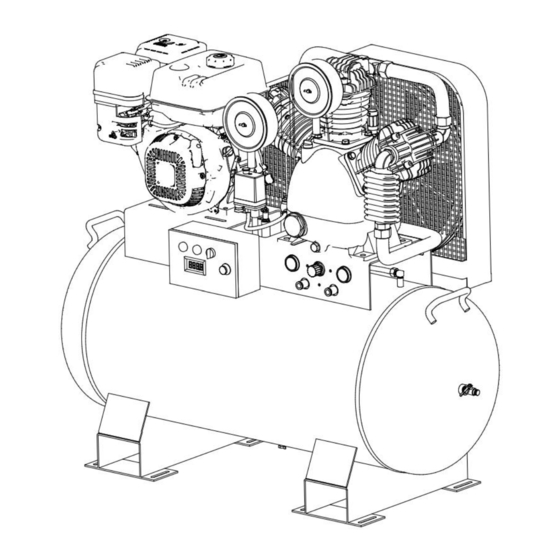
Page 7: Component Identification
COMPONENT IDENTIFICATION... - Page 8 1. Engine Controls: Location of choke, engine speed and fuel valve. 2. Engine: Shipped with oil. Refer toengine Owner’s Manual for proper oil and capacity. 3. Check Valve: Let the air fill the air tank through the check valve without letting the air go back. 4.
-
Page 9: Safety
SAFETY HAZARD SIGNAL WORD DEFINITIONS This is the safety alert symbol. It is used to alert you to potential personal injury hazards. Obey all safety messages that follow this symbol to avoid possible injury or death. DANGER Indicates a hazardous situation, which if not avoided, will result in death or serious injury. WARNING Indicates a hazardous situation, which if not avoided, could result in death or serious injury. -
Page 10: Safety Labeling
SAFETY LABELING SAFETY DECAL LOCATIONS WARNING: ALWAYS make sure safety labels are in place and in good condition. On-Product Warning Labels Location Description TMG-MACH-4176 TMG-MACH-4174 TMG-MACH-4173 TMG-MACH-4175 TMG-MACH-4177 TMG-MACH-4074... -
Page 11: Safety Decals
SAFETY DECALS... -
Page 12: Initial Set-Up
INITIAL SET-UP STEP 1. INSPECT & UNPACK Upon receipt, inspect air compressor for missing or damaged parts. Verify that it is the air compressor you ordered. See “Component Identification” section of this manual for a diagram of the compressor and its components. STEP 2. -
Page 13: Step 3. Mounting
DANGER: Carbon monoxide hazard Exhaust fumes from the engine contain carbon monoxide (CO), a poisonous gas you cannot see, smell, or taste. The CO generated by the engine can rapidly accumulate, even in areas that appear to be well ventilated, resulting in dangerous and fatal concentrations within minutes. -
Page 14: Step 4. Electrical Starting: Battery Procedure
STEP 4. ELECTRICAL STARTING: BATTERY PROCEDURE (WITHOUT INCLUDE) In addition to the auto starter, the engine is capable of recoil starter if auto start fault. When you use auto start, will require the purchaser to provide a hook-up to an external 12-volt size battery . Battery should have a minimum rating of 20 amp-hour. You may also choose to use a “jump”... -
Page 15: Operation
OPERATION FOLLOW SAFETY RULES FOR OPERATION Before starting the compressor, review the safety rules found below and throughout the manual. WARNING Failure to follow safety rules may result in serious injury or death to the operator or bystanders. Instruct operators. Owner must instruct all operators in safe set-up and operation. Do not allow anyone to operate the compressor who has not read the Owner’s Manual and been instructed on its safe use. -
Page 16: Check And Fill Gasoline Tank
Pump: The compressor pump capacity is 38 oz. Use SAE 30 Breather Cap non-detergent pump oil prior to break-in. You may use synthetic lubricants after 50 hour break-in. See “ Appendix A: Lubricants and Compatibility ” for a list of suitable and alternative lubricants. CAUTION: Synthetic lubrication hazard If you will be using a synthetic lubricant, all downstream Oil Cap... -
Page 17: Inspect Fuel System/Check For Leaks
Inspect Fuel System/Check for Leaks Inspect fuel system for leaks BEFORE starting compressor. Look for: Signs of leaks or deterioration ● Chafed or spongy fuel hose ● Loose connections ● Loose or missing fuel hose clamps ● Damaged gasoline tank ●... -
Page 18: Air Hose And Tool Use
WARNING: Overheating This compressor is not equipped with “auto shut off”. Do not allow to overheat. Failure to allow adequate ventilation or restrict the air flow may cause the machine to overheat. WARNING: Inflatables/Low PSI tire Never use compressor to inflate small low- pressure objects, i.e., balloons/inflatables, small or low volume PSI tires. It is easy to over- pressurize them, causing them to rupture. -
Page 19: Attaching Air Hose And Tools
Attaching Air Hose and Tools CAUTION: Air tools hazard Do not attach air tools to open end of the hose until start-up is completed and the unit checks out OK. 1. Connect air hose to ball valve outlet. 2. Connect tool to other end of the hose. 3. - Page 20 Malfunction during operation. Immediately turn off the compressor if any of the following conditions arise during operation: Excessive change in engine speed, slow orfast ● Overheating ● Excessive vibration ● Unusual noise ● Flame or smoke ● Air leakage ● To stop the compressor in an emergency: 1.
-
Page 21: Storage
STORAGE When you are finished using the compressor, you must: Make sure the compressor is shut down and all tools are disconnected. (See “Shutdown” section.) ● Drain air receiver tank. ● Store the compressor properly. Detailed instructions are provided below. ●... -
Page 22: Maintenance & Repair
MAINTENANCE & REPAIR WARNING: Maintenance hazards ALWAYS shut off the engine, disconnect the spark plug wire from spark plug and release air pressure from the receiver tank before cleaning, adjusting, or servicing the compressor. Make sure all guards and shields are replaced before re-starting. MAINTENANCE SCHEDULE SUMMARY Item Frequency... -
Page 23: Inspect Air Filter
Inspect Air Filter Inspect the compressor’s air filter element on a weekly basis if used regularly or the first time it is being used after a prolonged period of no use. A dirty air filter will not allow the air compressor to operate at full capacity. Clean air filter when necessary. -
Page 24: Check Drive Belt For Tension And Alignment
Check Drive Belt for Tension and Alignment CAUTION: Pulley/sheave hazard Improper pulley/sheave alignment and belt tension can result in motor overload, excessive vibration, and premature belt and/or bearing failure. To prevent this from happening, check the pulley/sheave alignment and belt tension on a regular basis. -
Page 25: Troubleshooting
TROUBLESHOOTING This section provides a list of the more frequently encountered compressor malfunctions, their causes and corrective actions. Some corrective actions can be performed by the operator or maintenance personnel, and others may require assistance of a Service Center. PROBLEM POSSIBLE CAUSE Engine does not start. -
Page 26: Exploded View & Parts List
EXPLODED VIEW & PARTS LIST Main Exploded View 16 17... -
Page 27: Main Parts List
Main Parts List PART NO. DESCRIPTION PART NO. DESCRIPTION Belt Guard A Quick Connect 1/4” NPT Belt Guard B Air Pressure Gauge Belt, B1727 Check Valve Engine pulley Unloading Tube Gasoline Engine Pressure Switch Plug A Safety Valve 1/2” 60 Gallon Tank Plug B Drain valve 1/2"... -
Page 28: Pump Parts Exploded View
Pump Parts Exploded View... -
Page 29: Pump Parts List
Pump Parts List PART NO. DESCRIPTION PART NO. DESCRIPTION Bolt M10x45 Oil seal Spring washer ø10 Paper washer for back cover Head cover A Back cover Air Filter Breather M16x1.5 Exhaust Elbow M33X1.5 Pump Pulley T Joint M33x1.5 Plain washer ø10x40 Air pipe Bolt M10x35 Paper washer A for head cover... -
Page 30: Pneumatic Schematic
PNEUMATIC SCHEMATIC Please refer to our website for detailed warranty conditions and coverage. For the most up-to-date and comprehensive warranty information, visit www.tmgindustrial.com...
Need help?
Do you have a question about the TMG-GAC65 and is the answer not in the manual?
Questions and answers