
Related Manuals for Alstom GL314


Summary of Contents for Alstom GL314
- Page 1 Content Instruction Manual circuit- -breaker GL314 With spring operating mechanisms FK3- -1 Administrator First issue Compiled by Approved by 15--04--2004 J.C. Labadie X. Allaire 06--2004 D1211EN/02 E ALSTOM...
- Page 2 Content Instruction Manual This page is intentionally blank. 06--2004 D1211EN/02 E ALSTOM...
-
Page 3: Table Of Contents
L12- -016EN/01 L12- -103EN/02 Description of the interrupting chamber L13- -003EN/02 Pole operation (interrupting principle) L14- -007EN/01 Operating device L20- -001EN/04 gas monitoring Packaging - - Shipping and storage Packaging -- Identification -- Storage L22- -008EN/01 06--2004 D1211EN/02 E ALSTOM... -
Page 4: Installation
L31- -500EN/03 Installing terminals with preparation of contact sur- faces Installing the operating device L31- -789EN/01 L31- -901EN/02 Calculation of the SF gas filling pressure for using the pressure gauge (tool) L32- -007EN/01 Filling with SF 06--2004 D1211EN/02 E ALSTOM... - Page 5 Replacing the operating device FK3--1 Annexes L60- -010EN/02 Tooling and accessories Product safety sheets PS0000/A Acceptance criteria CA 103 141/3/004 Manual operations (FK3--1) 48.020.181E T51- -251EN/01 Instructions on the handling of used SF gas and decomposition products 06--2004 D1211EN/02 E ALSTOM...
- Page 6 Content Instruction Manual This page is intentionally blank. 06--2004 D1211EN/02 E ALSTOM...
-
Page 7: Technical Characteristics
Technical data Technical characteristics GL314 technical characteristics Performances The table below gives the circuit--breaker performances : Designation GL314 Rated voltage (r.m.s. value) Standard ANSI Rated normal current 3150 3150 Rated frequency Rated withstand current (peak value) Short- -time withstand current (r.m.s. value) - Page 8 Technical data Technical characteristics GL314 technical characteristics, continued The table below gives the SF gas characteristics : NOTE : Two pressure scales are possibles, depending the specifica- tions of the apparatus. GL314 Absolute pressure at 20C(68F) Filling absolute pressure for the insula- 0.75 MPa...
-
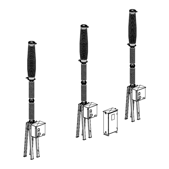
Page 9: Description And Operation
Description and operation General description of the circuit- - breaker Circuit- -breaker GL314 with spring operating mechanism FK3- - 1 Description The circuit--breaker is made up of three poles, each activated by a spring op- erating mechanism. Diagram Parts table... - Page 10 A housing (3) -- situated at the base of the column -- contains the lever and mechanism crank assembly and which operates the moving contact. The SF filling and monitoring device (7) is also situated on the housing. An external cylinder (4) mechanically links the pole to the operating device. 06--2003 L12- -016EN/01 E ALSTOM...
- Page 11 General description of the circuit- - breaker Support- - frame Description The support--frame (9) is fastened to the ground and supports all the circuit-- breaker components. The support--frame may be supplied by either ALSTOM or the customers. Diagram 06--2003 L12- -016EN/01 E ALSTOM...
-
Page 12: Operating Device
The door of the operating device (10) is equipped with two windows. These windows permit to display the optical signalization of the circuit--breaker state and closing spring state. Diagram Fastening The operating device is fastened on the housing (3). 06--2003 L12- -016EN/01 E ALSTOM... - Page 13 Description The marshalling cubicle (D) is fastened on the ground near the central pole. Included with : D The relays required to operate the circuit--breaker. D The interconnection terminals boards. D The terminals boards. Diagram 06--2003 L12- -016EN/01 E ALSTOM...
- Page 14 Description and operation General description of the circuit- - breaker This page is intentionally blank. 06--2003 L12- -016EN/01 E ALSTOM...
-
Page 15: Description Of The Interrupting Chamber
The chamber is made up of the following elements : Mark Component Terminal Fixed contact support Main contacts Moving contact Moving contact support Envelope Arcing contacts Fixed contact rod Insulating nozzle Valve 08--2000 L12- -103EN/02 E ALSTOM... - Page 16 Description and operation Description of the interrupting chamber This page is intentionally blank. 08--2000 L12- -103EN/02 E ALSTOM...
-
Page 17: Pole Operation (Interrupting Principle)
-- the main contacts (3), -- the moving contact (4), -- the moving contact support (5), -- the opposite terminal (1). In this module This module contains the stages of the pole operation : Stage Page Opening Closing 08--2000 L13- -003EN/02 E ALSTOM... - Page 18 (7) -- inside the operating device -- is released. The insulating tie--rod (8), directly activated by the opening spring (7), trans- mits the movement to the moving contact (4) which causes the contacts to separate. Continued on next page. 08--2000 L13- -003EN/02 E ALSTOM...
- Page 19 The (Vp) volume pressure decreases to the ambiant pressure by means of the valve (13) to allow the end of the opening. Continued on next page. 08--2000 L13- -003EN/02 E ALSTOM...
- Page 20 Consequently, the conventional autopneumatic effect developing in the vol- ume (Vp) is used mainly, to blast the arc. 08--2000 L13- -003EN/02 E ALSTOM...
- Page 21 The release of the energy stored up in the closing spring (15) causes displace- ment of the moving parts -- and so the closing of the interrupting chamber -- and also reloads the opening spring (7). 08--2000 L13- -003EN/02 E ALSTOM...
- Page 22 Description and operation Pole operation (Interrupting principle) This page is intentionally blank. 08--2000 L13- -003EN/02 E ALSTOM...
-
Page 23: Operating Device
THE CIRCUIT BREAKER MUST NOT BE OPERATED AT A SF PRES- SURE GAS LOWER THAN THE MINIMAL PRESSURE FOR THE INSULA- TION p In this module This module contains the following topics : Topic Page Description of the mechanism Auxiliary fittings Operating principle 07--2003 L14- -007EN/01 E ALSTOM... -
Page 24: Description Of The Mechanism
(15). This spring is a pressure helical type. The rotation torque -- created on the inertia flywheel (8) by means of the loaded closing spring (9) -- is balanced : closing latch (14) / roller (16). Diagram 07--2003 L14- -007EN/01 E ALSTOM... - Page 25 The cam (26) is installed on the clos- ing shaft (7). The closing latch (14) and the open- ing latch (6) are electrically activated by coils (22) “Closing” and (27) “Opening”. Continued on next page. 07--2003 L14- -007EN/01 E ALSTOM...
- Page 26 Circuit--breaker Open indicator (23) gives “LOADED” or “RELEASED” states of the closing spring. Closing spring Loaded If the auxiliary current supply fails, the hand- -held crank (21) permits the closing spring to be fully loaded. 07--2003 L14- -007EN/01 E ALSTOM...
-
Page 27: Operating Principle
(12) being driven by the gear wheel of the in- ertia flywheel (8). NOTE : A device pre- vents all closing opera- tions if the circuit--breaker already “CLOSED” position. Continued on next page. 07--2003 L14- -007EN/01 E ALSTOM... - Page 28 OPERATION AUTHORIZED ONLY IF THE OPERATING DEVICE IS CON- NECTED TO THE CIRCUIT BREAKER. THE CIRCUIT BREAKER MUST NOT BE OPERATED AT A SF PRES- SURE GAS LOWER THAN THE MINIMAL PRESSURE FOR THE INSULA- TION p 60° 07--2003 L14- -007EN/01 E ALSTOM...
-
Page 29: Sf 6 Gas Monitoring
Filling rated pressure for the insulation Alarm pressure for the insulation Minimal pressure for the insulation In this module This module contains the following topics : Topic Page Gas pressure and density Pressure measurement Measuring density Densimeter 01--2003 L20- -001EN/04 E ALSTOM... - Page 30 Conclusion Since it is difficult to measure the gas density directly, it is essential to know accurately its absolute pressure and temperature. 01--2003 L20- -001EN/04 E ALSTOM...
-
Page 31: Pressure Measurement
This is the reason why a ef- fective pressure gauge is used, pro- vision being made for corrections required by atmospheric pressure variations resulting from atmo- spheric disturbances and differ- ences of elevation. 01--2003 L20- -001EN/04 E ALSTOM... - Page 32 See the module “Calculation of the SF gas filling pressure to using the pressure gauge (tool)”. The real pressure is therefore : + ∆Pp real rated effective in accordance with temperature ∆Pp : correction in accordance with atmospheric pressure. 01--2003 L20- -001EN/04 E ALSTOM...
- Page 33 All the circuit--breaker’s rated performances are guaranteed up to the mini- m um s pec if ied am bient t em per at ur e and t he m inim um f unc t ional pressure for insulation ”p ”. Continued on next page. 01--2003 L20- -001EN/04 E ALSTOM...
- Page 34 SF gas effective pressure value. Needle position Colored area Direction GREEN None Perform a topping--up YELLOW operation. Abnormally low density, find the origin of the leak and contact ALSTOM T&D S.A. After- -sales Service. 01--2003 L20- -001EN/04 E ALSTOM...
-
Page 35: Packaging - - Shipping And Storage
The poles are filled with gas SF for transport purposes to an effective pres- sure of 0.3 bar 20°C (1,013 hPa). In this module This module contains the following topics : Topic Page Packaging Identifying sub--assemblies and their packaging Storage 09--2003 L22- -008EN/01 E ALSTOM... - Page 36 -- The poles. -- The operating devices vacuum--wrapped in a protective bag containing des- iccants. -- The different frame parts if the latter is supplied by ALSTOM. -- The marshalling cubicle. -- Connection cables, if supplied by ALSTOM. D The SF...
- Page 37 CASE No. POLE No. CIRCUIT--BREAKER IDENTIFICATION No. Place of the plates Choose and install the components identified by the plate (1) and self-- adhesive (3). 101 525 0010 SÉRIE Rep. 01/2 OUTSIDE PLATE INSIDE PLATE 09--2003 L22- -008EN/01 E ALSTOM...
- Page 38 ANY CHANGE OF LOCATION OF THE APPARATUS (EVEN AFTER COM- MISSIONING) SHOULD BE DONE AT A REDUCED PRESSURE OF 0.3 BAR. 09--2003 L22- -008EN/01 E ALSTOM...
-
Page 39: Erection Instructions
Store the shipping covers under shelter, for a possible future use. Respect references other modules, i.e. :“Tightening torquesI”. Warning No responsibility is taken over by ALSTOM T&D S.A. for damages and disturbances resulting out of non--adherence to the “Installation” modules. 07--1998 T30- -002EN/01 E ALSTOM... - Page 40 Installation Erection general instructions This page is intentionally blank. 07--1998 T30- -002EN/01 E ALSTOM...
-
Page 41: T31- -001En/02
In the assembling with screws, all the fastening screws must be “greased” be- fore torque tightening. Products used The table below gives the list of the used products for the screws before tight- ening : Designation ALSTOM item Supplier Supplier item reference reference --01835208... -
Page 42: Tightening Torques
The table below indicates the part of the screws to treat with the appropriate the product ? product before tightening depending on the assembling type : If assembling... With screws With bolts usual electrical connections Tapping or threading with seals Tapping or threading 06--2002 T31- -001EN/02 E ALSTOM... - Page 43 CLASS 8.8 STAINLESS A2--70, A4--70 STAINLESS A2--80, A4--80 M2,5 0,05 0,06 0,09 0,11 0,19 0,26 0,38 0,51 0,66 0,88 1,58 2,11 3,20 4,27 4,97 6,63 8,67 11,56 13,42 17,90 26,22 34,98 45,68 60,93 90,44 120,65 06--2002 T31- -001EN/02 E ALSTOM...
- Page 44 Installation Tightening torques This page is intentionally blank. 06--2002 T31- -001EN/02 E ALSTOM...
-
Page 45: T31- -003En/01
During the erection of the circuit--breaker, some particular mounting or check- ing operations will be realized. In this module This module contains the following topics : Topic Page Preparing and installing static seals Screw sealing Using a water pressure gauge 09--1998 T31- -003EN/01 E ALSTOM... - Page 46 Installation Erection general procedures Preparing and installing static seals Necessary products List of the ALSTOM products necessary for the installing : ALSTOM Diagram Designation reference --01861262 Can of ISOPROPANOL (1l) --01835265 MOLYKOTE 111 (100g tube) Process The table below gives the steps of installing static seals :...
- Page 47 NOTE : This procedure should be applied to all assemblages of parts submitted to SF pressure and electrical connection assembling. Necessary products List of the ALSTOM products and accessories necessary for the screw seal- ing : ALSTOM Diagram Designation...
- Page 48 The table below indicates the part of the screws to treat with the appropriate the product ? product before tightening depending on the assembling type : Assembling with screws Assembling with bolts Tapping or threading Tapping or threading 09--1998 T31- -003EN/01 E ALSTOM...
- Page 49 The displacement H should be less than 10 mm. At the end of the inspection, pull the adapter of the water pressure gauge and replace the leak test plug (5) or (6) and its seal (7), where required. 09--1998 T31- -003EN/01 E ALSTOM...
- Page 50 Installation Erection general procedures This page is intentionally blank. 09--1998 T31- -003EN/01 E ALSTOM...
-
Page 51: L31- -059En/01
The pole are filled with SF gas for transport purposes to an effective pressure of 0,03 MPa at 20°C (101.3 kPa). Necessary tools List of the necessary ALSTOM tools for the checking for presence of SF in poles : Mark Diagram... - Page 52 D It is of prime importance that the presence of SF gas in pole be verified before going any further with installation 06--2003 L31- -059EN/01 E ALSTOM...
- Page 53 Customer Service. D Replace the valve--cap (4) and remove the filling tool (3). D Re--install the plug (1), ap- plying a tightening torque of 4 daN.m; leak--tightness is only guaranteed if this condi- tion is respected. 06--2003 L31- -059EN/01 E ALSTOM...
- Page 54 Installation Checking for presence of SF gas in poles This page is intentionally blank. 06--2003 L31- -059EN/01 E ALSTOM...
-
Page 55: L31- -090En/01
This module contains the following topics : Topic Page Checking the presence of the stop ring of the “fusible” pin Installing the stop ring “site” of the “fusible” pin (in case of absence of the stop ring) 03--2004 L31- -090EN/01 E ALSTOM... - Page 56 Checking the presence of the stop ring of the “fusible” pin Visual inspection Check the presence of the stop ring (3) of the “fusible” pin. NOTE : If the stop ring (3) is absent, install the stop ring “site”. 03--2004 L31- -090EN/01 E ALSTOM...
- Page 57 Checking for presence of stop ring of the “fusible” pin Installing the stop ring “site” of the “fusible” pin (in case of absence of the stop ring) Necessary List of the ALSTOM components necessary for the assembling : components Mark Diagram Designation Number Stop ring “site”...
- Page 58 Installation Checking for presence of stop ring of the “fusible” pin This page is intentionally blank. 03--2004 L31- -090EN/01 E ALSTOM...
-
Page 59: L31- -113En/01
Installation Support- - frame assembly Presentation Reminder Frames may be supplied by either ALSTOM or the customer. In this module This module contains the following topics : Topic Page Components necessary for the operation Support--frame components (per pole) Preparing the column... - Page 60 (3 m) Lifting equipment Provide for appropriate lifting equipment : (3,000 daN) (minimum) H + 2 m Handling The support--frame assembly operations and lifting the pole should be performed by at least two per- sons. 06--2003 L31- -113EN/01 E ALSTOM...
- Page 61 Installation Support- - frame assembly Support- -frame components (per pole) Introduction If the support--frame is supplied by ALSTOM, check the necessary compo- nents to the assembling. Necessary List of the ALSTOM components necessary for the assembling : components Mark Diagram...
- Page 62 -- first, the interrupting--chamber extremity (4) on a wood wedge, -- second, the upper part of the housing (10) on a wood wedge to ensure the correct installing of the frame supports. = 260 mm minimum £X/2 06--2003 L31- -113EN/01 E ALSTOM...
- Page 63 18 daN.m With the aid of two flexible lifting straps, position the frame--support (3) onto the housing (10) and fasten it with the use of the screws (7). H M16--35 18 daN.m Continued on next page. 06--2003 L31- -113EN/01 E ALSTOM...
- Page 64 The table below gives the steps of installing the supports of the frame : Step Action Position the last frame--supports (2) onto the housing (10) and fasten with the use of the screws (7). H M16--35 H M16--35 18 daN.m 18 daN.m 06--2003 L31- -113EN/01 E ALSTOM...
-
Page 65: L31- -201En/02
List of the ALSTOM components necessary for the assembling : components Mark Diagram Designation Number (12) Thick washer Necessary tools List of the necessary ALSTOM tools for the lifting and positionning of the pole : Mark Diagram Designation Number LIFTING STRAP (3 m -- 1000 kg) In this module... - Page 66 By means of a lifting device hoist the pole up whilst allowing it to rest on the base of the frame. Place the trip ropes (10) on the support legs of the frame (9) to ensure guid- ance of the pole at the time of lifting. Lift the pole with precaution. 07--2003 L31- -201EN/02 E ALSTOM...
- Page 67 If necessary, place shims under the supports of the frame so that the upper plate is level. Install the upper washers (12) and clamp the whole to the ground using nut. Remove the lifting straps. Check the tightening torques of all frame screws. 18 daN.m 07--2003 L31- -201EN/02 E ALSTOM...
- Page 68 Installation Lifting and positionning the pole This page is intentionally blank. 07--2003 L31- -201EN/02 E ALSTOM...
-
Page 69: L31- -500En/03
Installation Installing terminals with preparation of contact surfaces Presentation Necessary products List of the ALSTOM products and accessories necessary for the installing : and accessories ALSTOM Diagram Designation reference --01861262 Can of ISOPROPANOL (1l) --01835106 Vaseline 204--9 --01835118 Contactal grease... - Page 70 Dry rub with fine emery cloth. Eliminate the dust produced. Coat with CONTACT GREASE. Wipe with a clean rag, leaving just a thin layer of grease. Rub over the grease with water- proof abrasive paper A400. 08--2000 L31- -500EN/03 E ALSTOM...
- Page 71 CONTACT GREASE to seal the screws. H M12--45 5 daN.m Comment D The electrical resistance value of the assembly should be : R 2←τ D Before installing H.V. connectors, prepare the contact surfaces in the same way. 08--2000 L31- -500EN/03 E ALSTOM...
- Page 72 Installation Installing terminals with preparation of contact surfaces This page is intentionally blank. 08--2000 L31- -500EN/03 E ALSTOM...
-
Page 73: L31- -789En/01
Installation Installing the operating device Presentation Necessary product Grease MOBILPLEX 47 (screws greasing) Necessary ALSTOM List of the ALSTOM tools necessary for the installing : tools Mark Diagram Designation Number Lifting strap Lifting equipment Provide an appropriate lifting equipment (130 daN). - Page 74 Proceed in the same way for the right side panel. Operating shaft Check the presence of the seal (11) on the operating shaft (13). Check the presence of grease (ASEOL 0--365.2) on the operating shaft (13). 01--2004 L31- -789EN/01 E ALSTOM...
- Page 75 -- with a positioning “fusible” pin (4) of the pole operating shaft. Check the presence of this pin. This pin must remain in place during all the operation of assembly of the oper- ating mechanism, IT IS STRICTLY FORBIDDEN TO REMOVE IT. 01--2004 L31- -789EN/01 E ALSTOM...
- Page 76 Installation Installing the operating device Coupling the operating device Necessary List of the ALSTOM components necessary for the operation : components Mark Diagram Designation Number Screw H M16--80 Washer (979997001) Nut H M16 Installing the Install the screws (9) -- equipped with the washers (10) -- inside the operating fastening screws device.
- Page 77 Introduce the operating device shaft (13) into the cylinder (12). D Put the washers (10) and nuts (14) in place and tighten to recommended torque. D Remove the flexible strap. H M16 18 daN.m 01--2004 L31- -789EN/01 E ALSTOM...
- Page 78 Connecting up the Connect the wires from the electrical contact SF densimeter (18) cable (19) contact densimeter to the operating mechanism terminal block, in accordance with the relative cable diagram. 01--2004 L31- -789EN/01 E ALSTOM...
- Page 79 Installation Installing the operating device Installing side panels of the operating device Process Reinstall the side panels (3) of the operating device using new nuts (2). NYLSTOP 1,6 daN.m 01--2004 L31- -789EN/01 E ALSTOM...
- Page 80 DO NOT SUPPLY THE OPERATING MECHANISM MOTOR WITH CUR- RENT TO AVOID THE CLOSING SPRING BEING RELOADED. THE CIRCUIT BREAKER MUST NOT BE OPERATED AT A SF PRES- SURE GAS LOWER THAN THE MINIMAL PRESSURE FOR THE INSULA- TION p 01--2004 L31- -789EN/01 E ALSTOM...
-
Page 81: L31- -901En/02
In this module This module contains the following topics : Topic Page Example of the filling pressure calculation Calculation of the filling pressure at site Values of the SF gas pressures in accordance with the temperature 08--2000 L31- -901EN/02 E ALSTOM... - Page 82 Calculate the rated effective pres- sure p 0.6111 MPa 0.603 + 0.0081 Filling is carried out to the calcu- Pure SF gas filling pressure lated pressure, plus 0,01 MPa, 0.6211 MPa that is to say : 0.6111 + 0.01 08--2000 L31- -901EN/02 E ALSTOM...
- Page 83 Transfer the value (C) " Calculate the rated effective pressure (E + C) " F The filling with SF gas is carried out to the calculated pressure, plus 0.01 MPa, (F + 0.01) " G 08--2000 L31- -901EN/02 E ALSTOM...
- Page 84 0,713 0,724 0,618 0,589 0,883 0,752 0,716 0,728 0,621 0,592 0,887 0,755 0,719 0,732 0,624 0,595 0,890 0,758 0,722 0,735 0,628 0,598 0,894 0,761 0,725 0,739 0,631 0,601 0,898 0,764 0,728 Continued on next page. 08--2000 L31- -901EN/02 E ALSTOM...
- Page 85 0,631 0,596 0,618 0,514 0,485 0,764 0,634 0,599 0,622 0,516 0,488 0,767 0,637 0,601 0,625 0,519 0,490 0,770 0,639 0,604 0,628 0,522 0,493 0,773 0,642 0,606 0,631 0,524 0,495 0,776 0,645 0,609 0,634 0,527 0,498 08--2000 L31- -901EN/02 E ALSTOM...
- Page 86 Installation Calculation of the SF gas filling pressure for using the pressure gauge (tool) This page is intentionally blank. 08--2000 L31- -901EN/02 E ALSTOM...
-
Page 87: L32- -007En/01
TRANSPORTATION, PEOPLE PRESENT AT THE GAS FILLING OPERA- TION SHOULD SHELTER THEMSELVES OR STAY AT A MINIMUM PROTECTION DISTANCE (ABOUT 50 m). Necessary equipment List of the necessary ALSTOM equipment and tools for the filling with SF and tools gas : Mark... - Page 88 (9) of the pressure reduc- gauge (11). er (reduced flow rate). Start filling again until the re- quired pressure is reached. Close in this order : the tap (7), then the cock (9). 07--2002 L32- -007EN/01 E ALSTOM...
- Page 89 0--1 MPa (14) -- to the filling tool (2). S When the required pressure is confirmed, remove the gauge (14) and and store it away from humid- ity. Remove the filling tool (2) and refit the plug (17) (4 daN.m) 07--2002 L32- -007EN/01 E ALSTOM...
- Page 90 S Remove the plug (17) and install the filling tool (2). S Unscrew the valve--cap (3). S Connect the tube (15) -- of the gauge 0--1 MPa (14) -- to the filling tool (2). Continued on next page. 07--2002 L32- -007EN/01 E ALSTOM...
- Page 91 S Remove the filling tool (2) and re--install the plug (17), applying a tightening torque of 4 daN.m; leak--tightness is only guaranteed if this condition is respected. S Screw the valve--cap (3) on the filling tool (2). 07--2002 L32- -007EN/01 E ALSTOM...
- Page 92 Installation Filling with SF Checking gas- -tightness Necessary ALSTOM List of the ALSTOM tools necessary for the tightness inspection : tools Mark Diagram Designation Number Leak detector (optional) Process Make sure that the plug (17) is perfectly leak--tight using the leak detector (12).
- Page 93 £ 0°C (32°F) for an am- bient temperature of 20°C (68°F), this applies for a unit filled to its nominal pressure for 2 or 3 months. 07--2002 L32- -007EN/01 E ALSTOM...
- Page 94 Installation Filling with SF This page is intentionally blank. 07--2002 L32- -007EN/01 E ALSTOM...
-
Page 95: Pre--Commissioning Inspections
ING ON THE EQUIPMENT. In this module This module contains the following checking inspections : Inspections Page Operating device Test operations Information concerning the stop ring of the “fusible” pin Removing the stop ring “site” 04--2004 L34- -004EN/04 E ALSTOM... - Page 96 SF pressure This inspection should be undertaken once all the filling and pressure control operations are finished. Execute this checking according to instructions given in module ”SF monitoring”. 04--2004 L34- -004EN/04 E ALSTOM...
-
Page 97: Operating Device
Pre- -commissioning inspections Operating device Measurements Note the supply voltage of motors on the operating mechanism terminals. Inspection Check that the following items are working correctly : -- heating, -- connections on terminals (no excessive tightening). 04--2004 L34- -004EN/04 E ALSTOM... -
Page 98: Test Operations
AFTER THE FIRST TEST OPERATION, IT IS FORBIDDEN TO REMOVE THE OPERATING MECHANISM WITHOUT USING THE BLOCKING TOOL (4). NOTE : To remove the operating mechanism, see in “Maintenance”, the module “Replacing the operating device FK3- -1”. 04--2004 L34- -004EN/04 E ALSTOM... - Page 99 The table below indicates the procedure -- after the first operation of the circuit breaker -- according to the type of stop ring : Case Stop ring type Direction None None None See : Removing the stop ring “site” 04--2004 L34- -004EN/04 E ALSTOM...
- Page 100 : Closing spring Released Remove the stop ring “site” and the broken part of the “fusible” pin. Switch--on the motor supply The motor starts--up and reloads circuit. the closing spring. 04--2004 L34- -004EN/04 E ALSTOM...
-
Page 101: Maintenance Plan
(or a gas mixture) and require only a reduced amount of maintenance. In this module This module contains the following topics : Topic Page Maintenance plan Maintenance operations Detail of maintenance operations 06--2004 L51- -003EN/03 E ALSTOM... - Page 102 D operating life time used the most, then to adapt ³ 20 years Overhaul the maintenance programme D number mechanical other breakers cycles ³ 3,000 depending on the results D electric wear limit observed. 06--2004 L51- -003EN/03 E ALSTOM...
-
Page 103: Maintenance Operations
Change door seal, side panels seal and roof seal. Measure operating times for poles and auxiliary contacts. J J J J Carry out operations at recommended duties and rated J J J J voltage. Change (or recondition) interrupting chambers. 06--2004 L51- -003EN/03 E ALSTOM... - Page 104 D Application coat polyurethane lacquer using a brush. Products used : D RUMCOAT EEVA primer by DERIVERY ref. 333103. D Polyurethane lacquer 780 by DERIVERY, ref. depending on color of equipment. Continued on next page. 06--2004 L51- -003EN/03 E ALSTOM...
- Page 105 Abnormally low density, find the origin of the leak and contact ALSTOM T&D S.A. After- -sales Service. NOTE : If the intersection is in either the yellow or red zone, without any particular indication from the electrical contact densimeter, verify the concordance of different information sources to find the defective element and then replace it.
- Page 106 If necessary, clean these using a dry rag. If anomalies are found contact : ALSTOM T&D SA, After--sales Service in order to change the defective parts. Interrupting Check the condition of interrupting chambers. This operation necessitates...
-
Page 107: L51- -051En/01
Example : it is possible to perform 40 interruptions on a current of 20 kA. (*) Normal guarantee. In certain special operation conditions, other values may be guaranteed. I (kA) Diagram 20 30 1000 3000 Number of interruptions 11--1999 L51- -051EN/01 E ALSTOM... - Page 108 Maintenance Electrical wear limits This page is intentionally blank. 11--1999 L51- -051EN/01 E ALSTOM...
-
Page 109: L51- -107En/01
Maintenance Electrical contact densimeter threshold inspection Presentation Necessary tools List of the ALSTOM tools necessary for the operation : Mark Diagram Designation Reference Number --02842117 (11) Gauge 0--1 MPa N55161602 --02557208 (17) Pressure reducer N55161601 Test lamp --02861501 Electrical contact densime-... - Page 110 Connection valve block the threshold inspection. Connection : connection valve Linking pipe block -- threshold inspection tank. Seals used for the connection Set of seals valve block and replacing the densimeters of the three poles. 06--2003 L51- -107EN/01 E ALSTOM...
- Page 111 (2), of the circuit-- breaker, using screws (8). Install the densimeter (1) on the connection valve block H M6--20 (5) using screws (15). H M6--20 NOTE : Before installing, check the presence of seals on the densimeter. 06--2003 L51- -107EN/01 E ALSTOM...
- Page 112 NOTE : Keep the end of the tube (6) in high position to keep the SF gas which it contains and to prevent damp air from entering. Connect the pipe (6) on the valve (24) of the connection valve block (5). OPEN CLOSE (leak) 06--2003 L51- -107EN/01 E ALSTOM...
- Page 113 (11). gauge (tool)”. Start filling again until the required pressure is reached. Close in this order : the tap (21), then the cock (22). Open Closed Continued on next page. 06--2003 L51- -107EN/01 E ALSTOM...
- Page 114 D Proceed in the same way to check the contact of “Minimal pressure for the insulation” OPEN CLOSE (leak) If one of the thresholds does not comply with the specified value, re- place the densimeter. 06--2003 L51- -107EN/01 E ALSTOM...
- Page 115 (27) on the densimeter (1), referring to “Preparing and installing static seals” in ”Erection general proce- dures”. Install the densimeter (1) on the housing cover (2), of the circuit--breaker, using screws (8). H M6--20 0,7 daN.m 06--2003 L51- -107EN/01 E ALSTOM...
- Page 116 “PRESSURE GAUGE” valve threshold inspection tank (4). Disconnect the pipe (23) from the “SUPPLY” valve of the threshold inspection tank (4). Put away the threshold inspection tank (4) into the densimeter threshold inspection case. 06--2003 L51- -107EN/01 E ALSTOM...
-
Page 117: L51- -302En/01
In this module This module contains the following topics : Topic Page Positions of optical signalization Safety measures Preparing the operating device Replacing an opening or closing electro--magnet Resumption of service Lubrication Cleaning the windows 10--1999 L51- -302EN/01 1/10 E ALSTOM... - Page 118 Positions of optical signalization “A” position Circuit-- Closing spring breaker Loaded Open “B” position Circuit-- Closing spring breaker Released Closed “C” position Circuit-- Closing spring breaker Loaded Closed “D” position Circuit-- Closing spring breaker Released Open 10--1999 L51- -302EN/01 2/10 E ALSTOM...
-
Page 119: Safety Measures
: 1 -- Close Open 2 -- Open Check the optical Check that the operating mechanism’s optical signalization shows the sym- signalization bols below : Circuit-- Closing spring breaker Released Open 10--1999 L51- -302EN/01 3/10 E ALSTOM... -
Page 120: Removing Side Panels
Take the roof plate (4) from the operating device by removing the nuts (8). roof plate NOTE : The spacers (7), washers (6) and screws (5) stay on the roof plate. H M6--60 0,7 daN.m 10--1999 L51- -302EN/01 4/10 E ALSTOM... - Page 121 Remove the core (11). Remove the faulty coil and replace it by a new one carrying the same reference. Reinstall the core (11). Reinstall the blade spring (10). Connect supply wires to the new coil (9). 10--1999 L51- -302EN/01 5/10 E ALSTOM...
-
Page 122: Resumption Of Service
Installing the side Insert the side panel (3) under the edge of the roof plate (4). Press it down to panels insert the mounting screws and fasten using new nuts (2). NYLSTOP Continued on next page. 10--1999 L51- -302EN/01 6/10 E ALSTOM... - Page 123 Check the optical Check that the operating mechanism’s optical signalization shows the sym- signalization bols below : Circuit-- Closing spring breaker Loaded Open Conclusion The circuit--breaker is ready for normal use. 10--1999 L51- -302EN/01 7/10 E ALSTOM...
- Page 124 D Lubricate later with any other oil. D Spray parts of the apparatus with a protective liquid against corrosion or with any kind of lubricating oil. Mixture with other lubricants can cause the layer of grease to become too hard. 10--1999 L51- -302EN/01 8/10 E ALSTOM...
-
Page 125: Cleaning The Windows
Maintenance Intervention on the operating device Cleaning the windows Recommended To clean the windows, use exclusively soapy water. product DO NOT USE SCOURING PAD. 10--1999 L51- -302EN/01 9/10 E ALSTOM... - Page 126 Maintenance Intervention on the operating device This page is intentionally blank. 10--1999 L51- -302EN/01 10/10 E ALSTOM...
-
Page 127: L51- -800En/04
CATOR IS IN THE POSITION BELOW. Circuit--breaker Closing spring Open Released Lifting equipment Provide an appropriate lifting equipment (130 daN). Necessary tools List of the ALSTOM tools necessary for removing the operating device : Mark Diagram Designation Number Lifting strap BLOCKING TOOL Replacing steps... - Page 128 : Closed 1 -- Open 2 -- Close 3 -- Open Activate the closing handle and the opening handle like below : 1 -- Close Open 2 -- Open Continued on next page. 04--2004 L51- -800EN/04 2/12 E ALSTOM...
- Page 129 Maintenance Replacing the operating device FK3- -1 Safety measures, continued Check the optical Check that the operating device’s optical signalization shows the symbols be- signalization low : Circuit--breaker Closing spring Open Released 04--2004 L51- -800EN/04 3/12 E ALSTOM...
- Page 130 Deflate the pole, using gas recovery chart. DEFLATE THE CIRCUIT--BREAKER SF PRESSURE GAS TO 0.3 bar AT 20°C (1,013 hPa) REFERRING TO THE MODULE IN ANNEXES “Instruc- tions on the handling of used SF gas and decomposition products”. 04--2004 L51- -800EN/04 4/12 E ALSTOM...
- Page 131 If the pole is equipped with a stop ring (5) of the “fusible” pin (9), release the screw (6) and move the stop ring (5) in order to reach the positioning hole of the blocking tool (4). NOTE : Two possible cases (A or B). Continued on next page. 04--2004 L51- -800EN/04 5/12 E ALSTOM...
- Page 132 Holding of the coupling cylinder Blocking tool Screw the blocking tool (4) into the free hole allowed on the cylinder (12). This blocking tool is removed once removing and coupling of the oper- ating device is finished. 04--2004 L51- -800EN/04 6/12 E ALSTOM...
- Page 133 (3). NYLSTOP Take hold of the left side panel (3) from underneath, pull slightly towards the out- side, then downwards to re- move it. Proceed in the same way for the right side panel. 04--2004 L51- -800EN/04 7/12 E ALSTOM...
- Page 134 Disconnect the wires of the electrical contact SF densimeter (18) cable (19) contact densimeter from the operating device terminal block. cable L.V. cables Disconnect all the L.V. cables from the operating device terminal block. 04--2004 L51- -800EN/04 8/12 E ALSTOM...
- Page 135 (17) of the operating device before slinging. Remove the nuts (14) and washers (10). H M16 Remove the operating shaft (7) from the cylinder (12) and re- move the operating device (20). Continued on next page. 04--2004 L51- -800EN/04 9/12 E ALSTOM...
- Page 136 Remove the screws (9) and the washers (10). Insert the side panel (3) under the edge of the roof plate (4). Press it down to insert the mounting screws and fasten using nuts (2). NYLSTOP 04--2004 L51- -800EN/04 10/12 E ALSTOM...
- Page 137 If the pole is equipped with a stop ring (5) of the “fusible” pin (9), reposition the stop ring (5) and hold in place using the screw (6). NOTE : Stick the screw (6) using LOCTITE 225 and apply a tightening torque of 17 N.m. 04--2004 L51- -800EN/04 11/12 E ALSTOM...
- Page 138 SURE GAS LOWER THAN THE MINIMAL PRESSURE FOR THE INSULA- TION p Process To make this operation, refer to the modules : S Calculation of the SF gas filling pressure for using the pressure gauge (tool) S Filling with SF 04--2004 L51- -800EN/04 12/12 E ALSTOM...
-
Page 139: L60- -010En/02
Only the tools and accessories specified on ordering are delivered. Commer- cially available tools (e.g. : spanners, torque wrenches, spirit levels...) are not supplied. In this module This module contains the following topics : Topic Page Special tools Accessories 07--2003 L60- -010EN/02 E ALSTOM... - Page 140 Annexes Tooling and accessories Special tools Table of special The table below gives the ALSTOM special tools : tools NUMBER DESIGNATION D001875.. EMPTY Transport of SF TRANSPORT TRANSPORT filling tools and control filling tools and control CASE tools. (OPTIONAL) N55000401...
-
Page 141: Leak Detector
Annexes Tooling and accessories Special tools, continued Table of special The table below gives the continuation of ALSTOM special tools : tools, continued NUMBER DESIGNATION Electrical contact V0003731001 Inspection of densi- densimeter thresh- meter thresholds. old inspection case Handling of the pole... - Page 142 Annexes Tooling and accessories Accessories Table of accessories The table below gives the ALSTOM accessories : NUMBER DESIGNATION 42 kg --01861432 SF BOTTLE BOTTLE SF filling topping up filling topping--up. 20 kg --01861435 SF BOTTLE BOTTLE SF filling topping up filling topping--up.
- Page 143 Annexes Tooling and accessories Accessories, continued Table of accessories, The table below gives the continuation of ALSTOM accessories : continued NUMBER DESIGNATION CONTACTAL CONTACTAL Preparation of electri- Preparation of electri --01835118 01835118 GREASE cal contact surfaces. ASEOL 0--365.2 ASEOL 0 365.2...
- Page 144 Annexes Tooling and accessories This page is intentionally blank. 07--2003 L60- -010EN/02 E ALSTOM...
- Page 145 TRANSMISSION & DISTRIBUTION High voltage switchgear S U M M A R Y of PRODUCT SAFETY SHEETS for equipment manufactured by ALSTOM T&D - AHT SUBJECT Reference N° Revision Remarks Summary PS 0000/A Working environment PS 0001/A Handling Operations PS 0002/A...
- Page 146 This page is intentionally blank.
- Page 147 TRANSMISSION & DISTRIBUTION High voltage switchgear SAFETY SHEET WORKING ENVIRONMENT CAUSE OR ORIGIN OF HAZARD. Any negligence as regards site organisation may cause an accident. WORK REQUIREMENTS. All remedial action, for all life-cycles of the equipment, must be carried out in a safe working environment SAFETY INSTRUCTIONS.
-
Page 148: Safety Instructions
TRANSMISSION & DISTRIBUTION High voltage switchgear SAFETY INSTRUCTIONS 1 Personnel : Appropriate clothing, gloves, helmet, safety boots, harness, etc.. The personnel concerned must be familiar with the basic working regulations governing a given work station: mechanical, dielectric, pressure hazards, etc.. 2 Handling Equipment : This must be in good working order, regularly maintained, properly adjusted and compliant with the... - Page 149 TRANSMISSION & DISTRIBUTION High voltage switchgear SAFETY SHEET HANDLING OPERATIONS CAUSE OR ORIGIN OF HAZARD. Any handling operation may involve danger for the personnel for the equipment being handled for the installations or equipment in the vicinity WORK REQUIREMENTS. As a general rule, handling operations must be carried out by personnel familiar with the basic handling regulations, using equipment in good working order, and wearing the appropriate protective clothing or equipment Ensure that the condition of the cases is such that they can be safely handled (state of the wood, shock-...
- Page 150 Familiarity with the load to be handled (see details on the case). Use of the appropriate handling equipment : Type of sling(s), Correct slinging methods, Use of special ALSTOM handling equipment. Follow the handling instructions on : the cases (pictorial symbols: centre of gravity, slinging points, etc.), the assembly instructions.
- Page 151 TRANSMISSION & DISTRIBUTION High voltage switchgear SAFETY INSTRUCTIONS Handling of insulating jackets at transport pressure (300 hPa maximum). Ensure that cases have not been damaged during handling or prolonged storage. Follow the stacking instructions. It is essential to open cases from the top and to take care when unpacking.
- Page 152 This page is intentionally blank.
- Page 153 TRANSMISSION & DISTRIBUTION High voltage switchgear SAFETY SHEET PRESSURIZED EQUIPMENT CAUSE OR ORIGIN OF HAZARD. Our equipment includes gas pressure assemblies (SF , nitrogen, air, etc.) or fluids (oil). WORK REQUIREMENTS. • Comply with the storage, transport and operating instructions supplied with our equipment. •...
- Page 154 TRANSMISSION & DISTRIBUTION High voltage switchgear SAFETY INSTRUCTIONS Pressurized Equipment : General. Comply with the assembly instructions shown on both our equipment and the gas bottles. Before starting work on any pressurized piece of equipment, make sure there is no pressure. Before any handling, check to see how the equipment is fixed to its frame and how the frame is itself anchored.
- Page 155 TRANSMISSION & DISTRIBUTION High voltage switchgear SAFETY INSTRUCTIONS SF6 Pressure Equipment. See SF Safety Sheet. An effective pressure of 300 hPa, used for the transport and storage of our products, is not regarded as a potential hazard. Always fill the unit using the appropriate equipment, which should include a safety valve.
- Page 156 This page is intentionally blank.
-
Page 157: Use And Handling
TRANSMISSION & DISTRIBUTION High voltage switchgear SAFETY SHEET Use and Handling CAUSE OR ORIGIN OF HAZARD. Sulphur hexafluoride (SF ) is a gas which in its basic state is colourless, odourless and tasteless. It is not toxic, but it cannot sustain life. It is a heavy gas that is dispersed slowly into the atmosphere. In its natural state, SF is delivered and stored in pressurized tanks (bottles or spheres) at a pressure of approximately 20 bar at 20°C (in its liquid form) and complies with IEC standard 376. - Page 158 TRANSMISSION & DISTRIBUTION High voltage switchgear Whilst SF in its pure state is not toxic, the decomposition products have varying degrees of toxicity. They may irritate the skin, the eyes and the mucous membranes; and in massive amounts may cause serious lesions (oedema, heart failure, circulatory disorders and unconsciousness).
- Page 159 TRANSMISSION & DISTRIBUTION High voltage switchgear SAFETY INSTRUCTIONS Transport of SF Pure SF Contaminated SF PS 0004/A 1996-03-18 1998-08-12 3 / 3 Sheet N° Revision 1st issue Revision date Page...
- Page 160 This page is intentionally blank.
- Page 161 TRANSMISSION & DISTRIBUTION High voltage switchgear SAFETY SHEET CHEMICALS CAUSE OR ORIGIN OF HAZARD. Generally speaking, the products used for installation and commissioning are bought chemical products, namely : Hydraulic oil Grease Loctite Touching-up paint Isopropanol Drying agents These must be kept in their original packing and the tops replaced after use. Some packing products require careful handling as they may contain preservatives.
- Page 162 TRANSMISSION & DISTRIBUTION High voltage switchgear SAFETY INSTRUCTIONS Drying Agents Hydraulic Oil Consumables (Grease & Paint) (Isopropanol) Loctite PS 0005/A 1996-03-18 1998-08-12 2 / 2 Sheet N° Revision 1st issue Revision date Page...
-
Page 163: Electrical Equipment
TRANSMISSION & DISTRIBUTION High voltage switchgear SAFETY SHEET ELECTRICAL EQUIPMENT CAUSE OR ORIGIN OF HAZARD. Our equipment is subjected to high and low tension loads that could expose the personnel to the risk of electrocution. WORK REQUIREMENTS. The operating company is responsible for ensuring compliance with the safety instructions governing high tension. - Page 164 TRANSMISSION & DISTRIBUTION High voltage switchgear SAFETY INSTRUCTIONS High Tension. 1.1 Comply with the regulations governing the work station. 1.2 In the case of items equipped with capacitors, make sure they are discharged prior to removal and short- circuited while work is being carried out. Low Tension.
- Page 165 PS 0003/A. WORK REQUIREMENTS. Follow the relevant ALSTOM operating and maintenance instructions. Prior to any work on the control equipment and the motion transfer mechanism, disable the springs on mechanically operated units and bring pressure back to zero for hydraulically operated units.
- Page 166 2.2 Deactivate opening closing springs accordance with ALSTOM instructions. 2.3 Make sure that all safety rules are complied with while the work is being carried out. Hydraulic Mechanism. 3.1 Before any work is carried out, cut off power to the motor pump.
-
Page 167: Operation
WORK REQUIREMENTS. The operators concerned must be suitably qualified and must comply with the normal operating and maintenance instructions issued by ALSTOM Depending on the severity of the fault observed, the necessary corrective measures must be taken, e.g replenish the SF... - Page 168 (switch to 2nd threshold), no 1st threshold alarm complement. Loss of motor power : oil, compressed air, component failure. Activation of safety device, if fitted. Use only the appropriate products recommended by ALSTOM. Abnormal noise. PS 0008/A 1996-03-18 1998-08-12 2 / 2 Sheet N°...
-
Page 169: Maintenance
(standard or specific to ALSTOM) must be appropriate and in proper working order, any replacement parts must be ALSTOM parts. - Page 170 TRANSMISSION & DISTRIBUTION High voltage switchgear SAFETY INSTRUCTIONS Identify the equipment to be worked on and ensure it is switched off. Obtain as much information as possible from the user regarding the condition of the unit. Check that the unit is earthed both upstream and downstream.
- Page 171 Page-Sheet Le présent document est à la propriété de ALSTOM. Remis à titre This document is the sole property of ALSTOM. It is submitted on a confidentiel, il ne peut être communiqué à des tiers ni utilisé ou reproduit confidential basis and may not be passed on to third parties, used or qu’en stricte conformité...
- Page 172 T R A N S M I S S I O N & D I S T R I B U T I O N Appareillage haute tension VALIDITÉ VALIDITY DISJONCTEUR : GL314 CIRCUIT BREAKER PRESSION SF6 : Pre = 0,75 - 0,85 MPa (absolue) SF6 PRESSURE COMMANDE : MÉCANIQUE FK 3.1...
- Page 173 T R A N S M I S S I O N & D I S T R I B U T I O N Appareillage haute tension DURÉES DE FONCTIONNEMENT (en ms à tension assignée) MECHANICAL OPERATING TIMES ( in ms at rated voltage) DURÉES DES CHAMBRES TIMINGS OF CHAMBERS MANOEUVRE...
- Page 174 T R A N S M I S S I O N & D I S T R I B U T I O N Appareillage haute tension ÉCART ENTRE POLES (en ms à tension assignée) DEVIATIONS BETWEEN POLES (in ms at rated voltage) MANOEUVRE Maximum OPERATION...
- Page 175 Cette page est intentionnellement blanche.
- Page 176 ALSTOM Transmission & Distribution / Appareillage Haute Tension 130, rue Léon Blum -- BP 1321 -- 69611 Villeurbanne cedex -- France Téléphone : 33 (0) 4 72 68 34 34 -- Téléfax : 33 (0) 4 72 68 34 96...
- Page 177 FK 3-1 / FK 3-06 motor-wound spring operating mechanism Manual operations FK 3-1 / 3-06 motor-wound spring operating mechanisms for outdoor circuit breakers Administered by First issued Written by Released by 15.01.1998 E. Suter/TMA-SEH /hz E. Suter, TMA-SEH / 21.5.2003 21.5.2003 48.020.181E/2 © ALSTOM 1/26...
- Page 178 FK 3-X motor-wound spring operating mechanism for outdoor circuit breaker Contents Page Introduction Safety Manual operations possible Preparation of operating mechanism for manual opera- tions Slow closing Slow opening Manual discharge of closing spring Final steps after manual operations are complete 21.5.2003 48.020.181E/2 © ALSTOM 2/26...
-
Page 179: Introduction
Has the duty immediately to report any changes that interfere with safety Necessary conditions • The circuit breaker is in open position. for performance of • The circuit breaker is earthed on both sides. manual operations • The control voltage is disconnected. 21.5.2003 48.020.181E/2 © ALSTOM 3/26... - Page 180 • Injury may result from touching parts that are moving and/or spring- driven. • When turning on the control voltage, keep body parts away from WARNING parts of the equipment that are moving and/or spring-driven. 21.5.2003 48.020.181E/2 © ALSTOM 4/26...
- Page 181 • Malfunctions and damage to the spring operating mechanism may result. • The heating (anticondensation feature) must always be in opera- CAUTION tion, regardless of where the circuit-breaker is installed. 21.5.2003 48.020.181E/2 © ALSTOM 5/26...
-
Page 182: Manual Operations Possible
1. Slowly open Fig. position indicator CLOSED 1) 2. Manually discharge closing spring Note 1) If the spring operating mechanism has been operated with no circuit breaker, consult the manufacturer to identify any possible damage. 21.5.2003 48.020.181E/2 © ALSTOM 6/26... - Page 183 Fig. circuit breaker position indi- cator CLOSED • Slowly open • For inspection and ad- justment Closing spring charged, circuit Fig. breaker position indicator CLOSED • Slowly open • For inspection and ad- justment 21.5.2003 48.020.181E/2 © ALSTOM 7/26...
- Page 184 • Before performing manual operations, consult the manufacturer in order ate position to diagnose the fault and determine how to remedy it. Possible positions of the position indicators Spring position indicator in inter- Circuit breaker position indicator in mediate position intermediate position 21.5.2003 48.020.181E/2 © ALSTOM 8/26...
-
Page 185: Preparation Of Operating Mechanism For Manual Opera
• Injury may result from performing manipulations on the spring operating mechanism without disabling the manual releases. • Disable the manual releases to prevent inadvertent manual ac- WARNING tuation of the spring operating mechanism. 21.5.2003 48.020.181E/2 © ALSTOM 9/26... - Page 186 70.58 and slide as shown by arrow until manual releases are disabled. • Tighten M6 screws. Manual release disabling device 70.13 70.58 70.07 70.58 Manual release disabling 70.13 Manual TRIP release device 70.07 Manual CLOSE release 21.5.2003 48.020.181E/2 © ALSTOM 10/26...
- Page 187 • Then gently tighten the nut by hand. 71.20 71.20 Undervoltage release dis- abling device • Turn disabling lever from service Undervoltage release with integral disabling device position to disabled position. Disabling lever in service position Disabling lever in disabled position 21.5.2003 48.020.181E/2 © ALSTOM 11/26...
- Page 188 TRIP release 70.13. 70.05 70.13 70.05 Closing latch 70.71 70.13 Manual TRIP release 70.71 Closing latch disabling device Remove safety plate • Remove safety plate 70.48. 70.48 70.96 70.48 Safety plate 70.96 Securing screw 21.5.2003 48.020.181E/2 © ALSTOM 12/26...
- Page 189 71.08 Tie rod 70.95 Guide socket 71.09 Hex nut 70.96 Securing screw Relieve load on chain • Turn the tie rod clockwise about four more turns to charge closing spring further. The chain now bears no load. 21.5.2003 48.020.181E/2 © ALSTOM 13/26...
-
Page 190: Slow Closing
Closing spring discharging device 70.58 Manual release disabling plate 1) 71.20 Undervoltage release disabling device 1) 1) Required only for a spring operating mechanism equipped with an un- dervoltage release but no integral disabling feature 21.5.2003 48.020.181E/2 © ALSTOM 14/26... - Page 191 CLOSED, trip spring charged Remove slow- • Turn hex nut 70.75 counterclockwise until hook 70.74 is relieved of movement device enough load to allow removal of slow-movement device 70.72. 21.5.2003 48.020.181E/2 © ALSTOM 15/26...
-
Page 192: Slow Opening
70.16 has been relieved. 70.75 70.11 70.73 70.74 70.76 70.77 70.80 70.78 70.16 70.11 Roller lever 70.76 Distance sleeve 70.16 Trip latch 70.77 70.73 Support plate 70.78 Support latch 70.74 Hook 70.80 Stop sleeve 70.75 Hex nut 21.5.2003 48.020.181E/2 © ALSTOM 16/26... - Page 193 70.52 shows “circuit breaker OPEN”. 70.75 70.11 70.73 70.74 70.76 70.77 70.80 70.78 70.16 70.11 Roller lever 70.76 Distance sleeve 70.16 Trip latch 70.77 70.73 Support plate 70.78 Support latch 70.74 Hook 70.80 Stop sleeve 70.75 Hex nut 21.5.2003 48.020.181E/2 © ALSTOM 17/26...
- Page 194 Manual CLOSE release Operating state of spring operating Positions of position indicators mechanism after slow opening Spring position indicator shows closing Circuit breaker position indica- spring discharged or charged tor shows OPEN, trip spring discharged 21.5.2003 48.020.181E/2 © ALSTOM 18/26...
-
Page 195: Manual Discharge Of Closing Spring
71.16 can be engaged with the motor limit switch bracket spring discharged” and the axis of the motor limit switch lever as shown in the drawing. position Blocking the switch in this way prevents the auxiliary switch from rotating back into the starting position. 21.5.2003 48.020.181E/2 © ALSTOM 19/26... - Page 196 70.28 and closing latch 70.05 is approx. 20-30 mm. 70.28 70.05 FK 3-1 shown 70.56 70.97 70.30 70.05 Closing latch 70.56 Pinion 70.28 Roller 70.97 Pinion shaft 70.30 Crank wheel 21.5.2003 48.020.181E/2 © ALSTOM 20/26...
- Page 197 Injury may result. • After performing manipulations on the return stop, tighten the WARNING clamp shackle mounting screw to a torque of 5 Nm ±10%. 21.5.2003 48.020.181E/2 © ALSTOM 21/26...
- Page 198 • After performing manipulations on the return stop, tighten the CAUTION clamp shackle mounting screw to a torque of 5 Nm ±10%. Re-enable motor limit • Remove motor limit switch disabling plate 71.16 so that the motor limit switch switch can function again. 21.5.2003 48.020.181E/2 © ALSTOM 22/26...
-
Page 199: Final Steps After Manual Operations Are Complete
70.26 is under load again and closing spring discharging device 71.15 is free and can be withdrawn. 70.26 71.15 71.08 70.26 Closing chain 71.08 Tie rod 71.15 Closing spring discharging device 21.5.2003 48.020.181E/2 © ALSTOM 23/26... - Page 200 71.20. 71.20 Undervoltage release with inte- gral disabling feature Disabling lever in service position • Turn disabling lever from disabled position to service position. Disabling lever in disabled posi- tion 71.20 Undervoltage release disabling feature 21.5.2003 48.020.181E/2 © ALSTOM 24/26...
- Page 201 70.58 is normally not installed in this 70.13 version. • Unscrew M6 screws and remove 70.58 manual release disabling device 70.58. 70.07 70.58 Manual release disabling device 70.07 Manual CLOSE release 70.13 Manual TRIP release 21.5.2003 48.020.181E/2 © ALSTOM 25/26...
- Page 202 • Install side panels 78.01. For proper sealing of side panels against cabinet rims, dimension E (side panel to cabinet clearance) must be no greater than 5 mm. 78.01 78.01 Side panel Restore to service • Connect control voltage. 21.5.2003 48.020.181E/2 © ALSTOM 26/26...
- Page 203 Switchgear may only be opened after the preparations for scavenging have been completed. In this module This module contains the following topics : Topic Page Evacuation of SF gas apparatus Opening--up SF gas switchgear Recapitulation of important instructions 03--1999 T51- -251EN/01 E ALSTOM...
- Page 204 (observe the local regulations on emis- sion). Fill gas compartment if possible with nitrogen or dry compressed air at rated pressure and subse- quently, discharge outdoors (if possible through an adsorber fil- ter). 03--1999 T51- -251EN/01 E ALSTOM...
- Page 205 It is advisable to wash face, neck, arms and hands with soap and plenty of water before work--breaks and after stoppage of work. S Avoid eating, drinking, smoking or storing eatables in rooms or outdoors near to opened SF switchgear which may contain arc--decomposed powder. 03--1999 T51- -251EN/01 E ALSTOM...
- Page 206 Discard used items and filter--bags in such a manner that powder deposit does not spread. Before discarding neutralize used items. Avoid eating, drinking and storing eatables in rooms with opened switchgear which contains powder deposits. 03--1999 T51- -251EN/01 E ALSTOM...
- Page 207 This page is intentionally blank.
- Page 208 ALSTOM Transmission & Distribution / Appareillage Haute Tension 130, rue Léon Blum -- BP 1321 -- 69611 Villeurbanne cedex -- France Téléphone : 33 (0) 4 72 68 34 34 -- Téléfax : 33 (0) 4 72 68 34 96...
Need help?
Do you have a question about the GL314 and is the answer not in the manual?
Questions and answers