Table of Contents
Advertisement
Quick Links
OPERATORS
MANUAL
GENERATOR WITH
INDIRECT OIL FIRED
FORCED AIR HEATER
MODEL
ES500
SPECIFICATIONS
Dry weight:
..................................... 2540 LB [1270 KG]
Wet weight:
..................................... 3200 LB [1588 KG]
Firing Rate:
................................. 3.25 GPH [12.3 LPH]
Fuel Type:
.......................................................... ULSD
Fuel
Capacity ..............................82 GAL [310 L]
Storage:
Secondary containment ................... 200%
Heater:
Max burner rating ......... 390,000 BTU/HR
Heat exch. material .............. 304 Stainless
Burner .................................. Riello 40 F10
Fan motor ................................ ¾ hp, 120V
Fan capacity ........ 2500 CFM @ 1/2 in. wg
Generator:
Engine ................................. Kubota D1105
Generator .................................. Mecc Alte
Engine continuous power ................ 8 kW
Main breaker rating ............................ 50A
Voltage ............................................. 120V
Aux power ..................... 20A, 120V, 60Hz
Copyright © 2012 Equipment Source, Inc
Equipment Source, Inc.
th
8226 South 208
street Suite G103
Ph (877) 496-6119
www.equipmentsourcerental.com
.
Kent, WA 98032
www.equipmentsourceinc.com
Advertisement
Table of Contents
Troubleshooting

Related Manuals for ESI ES500

Summary of Contents for ESI ES500
- Page 1 OPERATORS MANUAL GENERATOR WITH INDIRECT OIL FIRED FORCED AIR HEATER MODEL ES500 SPECIFICATIONS Dry weight: ........2540 LB [1270 KG] Wet weight: ........3200 LB [1588 KG] Firing Rate: ......... 3.25 GPH [12.3 LPH] Fuel Type: ............ULSD Fuel Capacity ......82 GAL [310 L] Storage: Secondary containment ....
-
Page 2: Introduction
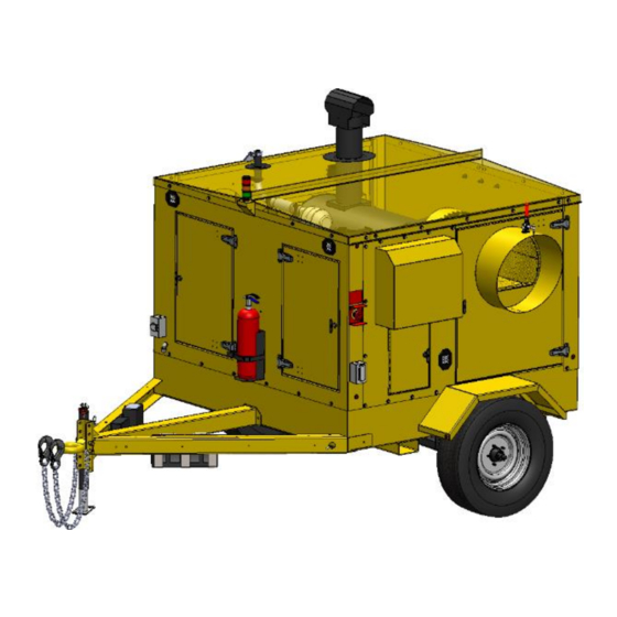
General Description The ES500 is a portable diesel engine generator set with one auxiliary indirect-fired forced-air heater that has a maximum firing rate of approximately 390,000 BTUs/hour. The heater system is intended for outdoor use and is trailer mounted for jobsite portability. The heater has an integrated 82-gallon [310 L] fuel storage tank with secondary containment. -
Page 3: Table Of Contents
ES500 Table of Contents Table of Contents Introduction ........................2 General Description ........................2 Manual Applicability ........................2 Manual Scope ..........................2 Language Translations ........................2 IMPORTANT SAFETY INSTRUCTIONS ................4 Training ............................4 Operating ............................4 Service ............................4 Transporting and Storage .................... -
Page 4: Important Safety Instructions
ES500 IMPORTANT SAFETY INSTRUCTIONS 2 IMPORTANT SAFETY INSTRUCTIONS Never attempt to operate this machine indoors. Exhaust fumes from the engine WARNING and heater can kill. SAVE THESE INSTRUCTIONS. This manual contains important instructions that should be followed during the operation and maintenance of the generator, battery and heater. -
Page 5: Transporting And Storage
ES500 Transporting and Storage 3 Transporting and Storage Dimensions and Weights Machine Weights *: Dry ............ 2540 LB [1153 KG] Wet 102638 ..........3200 [1452] Trailer 102638 Max GVW ......3300 [1497] Trailer 102638 Max Tongue ......330 [150] *All weights are approximate... - Page 6 ES500 Transporting and Storage Figure 1. Machine dimensions PN 102638. Red arrow denotes grounding lug location. 102638 Rev: A Copyright © 2013 Equipment Source, Inc...
-
Page 7: Lifting
Ensure that the trailer is registered with an applicable transport authority before NOTICE towing. ES500 fuel tank is not DOT rated to carry fuel while being transported. Therefore it must be emptied of fuel before transportation. Use the following procedure to prepare the machine for towing: 1. -
Page 8: Storage
ES500 Transporting and Storage Storage Failure to follow the shutdown procedure can cause serious damage to the burner NOTICE assembly. 3.5.1 Short-Term Storage (less than 90 days) 1. Shutdown the machine using the shutdown procedure (Section 4.11 Shutdown) 2. Verify that main breaker and control switches are in the off position 3. -
Page 9: Operation
4.1.1 General Guidelines The ES500 heater is an outdoor heater designed to safely heat enclosures using flexible duct connections. For efficient operation, keep duct lengths as short as possible. Excessive duct lengths will reduce air flow in the heat exchanger and cause the burner to cycle to control the outlet temperature. -
Page 10: Recommended Fuels And Fueling Instructions
Beacon Light The ES500 is equipped with a three beacon light that indicates the status of the heater. The green light turns on whenever the engine is running. The yellow light turns on whenever the fuel level dips below 20%. -
Page 11: Pre-Startup Checklist
ES500 Operation Pre-Startup Checklist Use the following checklist to determine whether the machine can be safely started and operated: 1. Machine is level and on stable ground (per Section 4.4) 2. Wheels are chocked 3. Exhaust vents are free of obstruction 4. -
Page 12: Monitoring And Operation
ES500 Operation 4.10 Monitoring and Operation 4.10.1 Daily Inspection Listen for abnormal sounds Check fluid levels Check containment for accumulation of liquids. Drain water if necessary. Observe burn quality (no smoke should be visible) Check if level and secure ... -
Page 13: Maintenance
ES500 Maintenance 5 Maintenance Some of the following maintenance operations should only be completed by a trained CAUTION technician. Do not attempt to open electrical panels or service the burner unless you are a trained technician. Maintenance Schedule Table 1. Maintenance Schedule... -
Page 14: Burner Maintenance
ES500 Maintenance The fan inlet should be periodically checked for icing when operated in winter conditions. If necessary, open both doors to access inlets to clear ice. Do not attempt to open the access doors unless the heaters are shutdown using the shutdown procedure. -
Page 15: Spark Arrestor Service
ES500 Maintenance Check tire pressure Test brake lights, turn signals and marker lights Test the breakaway battery and charge if necessary Check condition of the safety chains and jack stand Check tire condition and tightness of lug nuts 5.6.2... -
Page 16: Basic Trouble Shooting
NOTICE assemblies. The heater in the ES500 uses Riello 40 F10 burner. There are two internal thermostats (limit switches) on the heater, that control it, and two external (panel mounted) limit switches. If the enclosure cabinet gets too hot, the panel mounted thermostat (A) will shut the heater off. This switch automatically resets itself. -
Page 17: Fan Trouble Shooting
ES500 Basic Trouble Shooting Table 2. Burner Safeties/Controls Safety Purpose Heat exchanger over temperature Air blockage safety: shuts down burner if the See FVOHC-400 manual for location and wiring heat exchanger working air temperature exceeds diagram. 290F [143C]. (A) Enclosure over temperature... -
Page 18: Generator Engine Trouble Shooting
ES500 Basic Trouble Shooting Generator Engine Trouble Shooting Table 5. Engine Trouble Shooting Guide Problem Solution Engine controller fails (no low Check position of battery main disconnect oil pressure light when the key Check condition of battery ... - Page 19 The fan should draw approximately 17-20A if operating correctly. Check/replace the 40A Bosch style exhaust fan relay (see ES500/1000 wiring schematic) in the engine control panel. Replace fan 102638 Rev: A Copyright © 2013 Equipment Source, Inc...
-
Page 20: Electrical Schematics
Figure 5. ES500/1000 Generator Wiring This 20A breaker is only wired to the aft Flagro on the ES1000. Nothing is wired to it on the ES500, since the heater only has one Flagro. 102638 Rev: A Copyright © 2013 Equipment Source, Inc... - Page 21 ES500 Electrical Schematics Figure 6. 12V Engine Control Schematic 102638 Rev: A Copyright © 2013 Equipment Source, Inc...
- Page 22 ES500 Electrical Schematics Figure 7. Heater Wiring Diagram 102638 Rev: A Copyright © 2013 Equipment Source, Inc...
-
Page 23: Maintenance Records
ES500 Maintenance Records 8 Maintenance Records Table 6. Machine Data Machine Serial Number Engine Serial Number Generator Serial Number Trailer Serial Number Table 7. Maintenance Records Date Engine Hours Service Description of work completed Personnel Service Location 102638 Rev: A Copyright ©... - Page 24 ES500 Maintenance Records 102638 Rev: A Copyright © 2013 Equipment Source, Inc...
- Page 25 ES500 Maintenance Records 102638 Rev: A Copyright © 2013 Equipment Source, Inc...
- Page 26 ES500 Appendix A 9 Appendix A THIS PAGE INTENTIONALLY LEFT BLANK 102638 Rev: A Copyright © 2013 Equipment Source, Inc...
- Page 27 ES500 Appendix A Appendix item 1. Flagro (FVO-400) indirect fired space heater manual front page 102638 Rev: A Copyright © 2013 Equipment Source, Inc...
- Page 28 ES500 Appendix A Appendix item 2. Temperature feeler gauge adjustment instructions from FVO-400 manual 102638 Rev: A Copyright © 2013 Equipment Source, Inc...
- Page 29 OPERATING INSTRUCTIONS MANUAL (Please retain for future reference) FVO-400 INDIRECT FIRED SPACE HEATERS CERTIFIED FOR USE IN CANADA AND U.S.A. As per CSA B140.8 Portable Oil Fired Heaters / CSA B140.02003 Oil Burning Equipment Construction Heaters Unattended Type. Issue date October 1, 2008 FLAGRO INDUSTRIES LIMITED ST.
- Page 30 GENERAL HAZARD WARNING: FAILURE TO COMPLY WITH THE PRECAUTIONS AND INSTRUCTIONS PROVIDED WITH THIS HEATER, CAN RESULT IN DEATH, SERIOUS BODILY INJURY AND PROPERTY LOSS OR DAMAGE FROM HAZARDS OF FIRE, EXPLOSION, BURN, ASPHYXIATION, CARBON MONOXIDE POISONING, AND/OR ELECTRICAL SHOCK. ONLY PERSONS UNDERSTAND...
- Page 31 This heater is designed and approved for use as a construction heater under CSA B140.8 Portable Oil Fired Heaters / CSA B140.02003 Oil Burning Equipment. We cannot anticipate every use which may be made of our heaters. CHECK WITH YOU LOCAL FIRE SAFETY AUTHORITY IF YOU HAVE QUESTIONS ABOUT APPLICATIONS.
- Page 32 INSTALLATION: The installation of this heater for use with No.1, No.2, Diesel or Kerosene and shall conform with local codes or, in the absence of codes, with the National Fuel Gas Code ANSI Z223.1/NFPA 54. Installation of the unit shall be in accordance with the regulations of the authorities having jurisdiction or the CSA Standard B139.
- Page 33 FV SERIES CONSTRUCTION HEATER – VENTING REQUIREMENTS 1. VERTICAL FLUE TERMINATIONS VERTICAL FLUE RUN HORIZONTAL FLUE RUN - RISE RATIO 1:10 FLUE OUTLET OF HEATER 2. HORIZONTAL FLUE TERMINATIONS FLUE OUTLET OF HEATER EXTERIOR WALL VENT TERMINATION MUST BE A MINIMUM OF 2FT HIGHER THAN ANY POINT WITHIN 10FT.
- Page 34 DUCTING: Canvas heater duct with a minimum temperature handling of 300 deg F. including wire reinforcement to prevent collapsing. Heater is designed for use with 2 x 12” diameter ducts equipped with pin lock couplings (FV-HD12). Install ducting to outlet on the heater using pin-locks provided on collar of ducting.
-
Page 35: Start-Up Instructions
CAUTION: Do not have any source of ignition near the heater when draining tank. NOTE: No.1 fuel oil or kerosene is recommended for temperatures below -10º C / 8º F 11. Heat Exchanger should be cleaned if smokey conditions continue even after the air adjustments on the burner are made. -
Page 36: Safe Operation Precautions
IF HEATER FAILS TO START: Press manual reset button at rear of burner. (Red button). Check fuel level. There must be 2-4 gallons of fuel in the tank for the heater to start properly. Make sure there are no air locks in fuel lines or filter. Ensure proper power supply and extension cord is being used. - Page 37 COMBUSTION AIR ADJUSTMENTS: NOTE: Proper combustion air adjustment must be achieved using a certified combustion analyzer and smoke tester to ensure complete combustion. The air adjustment should be made to achieve 10% CO and No. 1 or “trace” smoke. (Bacharach Scale) SETTING THE AIR ADJUSTMENT PLATE Regulation combustion air flow is made...
- Page 38 BURNER SET-UP CHART ACTUAL NOZZLE FIRING RATE PUMP PRESSURE TURBULATOR SIZE DAMPER ± 5% SETTING SETTING 2.25 x 45° 4 - 6 2.75 2.00 x 60° * Note – Air damper setting is typically set at 4 for operation in colder temperatures.
- Page 39 In extreme cold conditions, cover the holes on the temperature feeler gauge using foil tape. Ensure that the temperature feeler gauge is readjusted for warmer weather conditions. Failure to do so may result in burning out fan switches- not covered under warranty. POWER SUPPLY INDICATOR LIGHT: The power supply indicator light will help detect any faulty power supplied to the heater such as;...
-
Page 40: Electrical Connections
ELECTRICAL CONNECTIONS It is advisable to leave the control box off the sub-base while completing the electrical connections to the burner. The burner may be controlled using either a DIRECT LINE VOLTAGE control circuit (120V AC 60 cycle) OR a LOW VOLTAGE control (24V AC 60 cycle) using a R8038A Honeywell switching relay or equivalent. - Page 41 APPLICATION FIELD WIRING REMOTE SENSING OF SAFETY LOCKOUT: The SAFETY SWITCH in the 530SE CONTROL BOX is equipped with a contact allowing remote sensing of burner lockout. The electrical connection is made at terminal 4 ( ) on the SUB- BASE.
- Page 42 INSERTION / REMOVAL OF DRAWER ASSEMBLY To remove drawer assembly, loosen SCREW (3), then unplug CONTROL BOX (1) by carefully pulling it back and then up. Remove the AIR TUBE COVER PLATE (5) by loosening the two retaining SCREWS (4). Loosen SCREW (2), and then slide the complete drawer assembly out of the combustion head as shown.
-
Page 43: Electrode Setting
NOZZLE PLACEMENT Remove the NOZZLE ADAPTER (2) from the DRAWER ASSEMBLY by loosening the SCREW (1). Insert the proper NOZZLE into the NOZZLE ADAPTER and tighten securely (Do not over tighten). Replace adapter, with nozzle installed, into drawer assembly and secure with screw (1). -
Page 44: Oil Line Connections
TURBULATOR SETTING Loosen NUT (1), then turn SCREW (2) until the INDEX MARKER (3) is aligned with the correct index number as per the Burner Set-up chart, on page 12. Retighten the RETAINING NUT (1) NOTE: Zero and five are scale indicators only. From left to right, the first line is 5 and the last line 0. - Page 45 PARTS DIAGRAM – FVO-400 FV-408 FV-438 FV-P01 FV-P06 FV-434 FVO-FR FV-405 40-113-D7 GALV & 40-108-8GALV FV-416A FV-436A FV-403 FV-P02 FVO-416H FV-402 FV-406 FV-401 FV-P11 FV-P05 FV-P10 FV-438 FVO-415 FV-407A FV-P08 FV-437 FV-404 FV-448 - 17 -...
- Page 46 FV-446 / FV-447 HC5-64 FV-431 FV-449SI FV-411 FV-409 FV-414B FVO-418 2103-C-CGA FV-421A FV-420A FVO-422A FVO-423B FV-437 FV-433 FV-407A FV-407G FV-433B - 18 -...
- Page 47 PARTS LIST FOR FVO-400 Part Number Part Description FV-401 PRIMARY FAN MOTOR FV-402 16" FAN BLADE FV-403 16" WHEEL FV-404 18" POWER CORD C/W PLUG END FV-405 SS HEAT EXCHANGER 40-113-D7GALV 1/2" X 7" GALVANIZED NIPPLE 40-108-8GALV 1/2" GALVANIZED CAP FV-406 HIGH LIMIT SWITCH (OUTLET) FV-407A...
- Page 48 FV-431 BURNER GASKET FV-433 FEELER GAUGE FV-433B FEELER GAUGE - SOLID FV-434 FRONT FACE PLATE (2 X 12") FV-434A FRONT FACE PLATE (1 X 16") FV-435H OIL BURNER NOZZLE (HI ALTITUDE) (1.75 X 60W) FV-435WC OIL BURNER NOZZLE (1.75 X 60W) FV-435B OIL BURNER NOZZLE (2.00 X 60W) FV-436A...
- Page 49 FVO-3007568 BLEEDER SCREW FVO-C7001010 PUMP FVO-C700-1029 IGNITION MODULE FVO-C7001034 BURNER MOTOR ACCESSORIES FV-HD12 12" X 12-FT HITEX VINYL DUCTING FV-HD12X25 12" X 25-FT HITEX VINYL DUCTING FV-HD16x25 16" X 25-FT HITEX VINYL DUCTING FV-THB THERMOSTAT C/W 25FT CORD/MALE PLUG END (AS OF 2011) FV-VK 6"...
Need help?
Do you have a question about the ES500 and is the answer not in the manual?
Questions and answers