Advertisement
Available languages
Available languages
ADULT ASSEMBLY REQUIRED DUE TO THE PRESENCE OF SMALL PARTS, SHARP
POINTS, SHARP EDGES AS RECEIVED
If you have any questions regarding assembly or if parts are missing, DO NOT return this item to the store
where it was purchased. Please call our toll-free customer service number and have your instructions and parts
list ready to provide the model name, part name or factory number:
Or visit our web site 24 hours a day, 7 days a week for product assistance at
THIS INSTRUCTION BOOKLET CONTAINS IMPORTANT SAFETY INFORMATION.
Thomasville™ is a trademark of HHG IPCo, LLC. ©HHG IPCo, LLC. thomasville.com
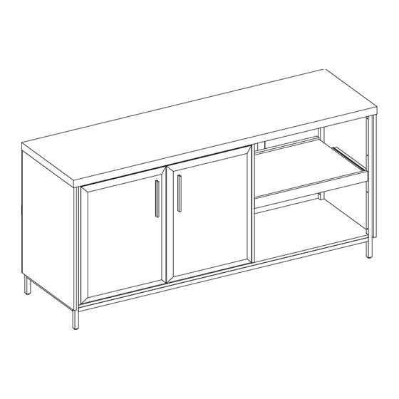
Alderbrook Credenza
Model # OD-ALBK65CR-TV
Pacific Standard Time: 8:30 a.m. - 4:30 p.m., Monday - Friday
www.whalenfurniture.com
Or e-mail your request to parts@whalenfurniture.com
PLEASE READ AND KEEP FOR FUTURE REFERENCE.
Date 2024-06-22
1-866-942-5362
Rev. 0001-A
LOT NUMBER:
DATE PURCHASED: /
/
Advertisement
Table of Contents

Subscribe to Our Youtube Channel
Related Manuals for HHG Thomasville Alderbrook Credenza OD-ALBK65CR-TV


Summary of Contents for HHG Thomasville Alderbrook Credenza OD-ALBK65CR-TV
- Page 1 Or visit our web site 24 hours a day, 7 days a week for product assistance at www.whalenfurniture.com Or e-mail your request to parts@whalenfurniture.com THIS INSTRUCTION BOOKLET CONTAINS IMPORTANT SAFETY INFORMATION. PLEASE READ AND KEEP FOR FUTURE REFERENCE. Date 2024-06-22 Rev. 0001-A Thomasville™ is a trademark of HHG IPCo, LLC. ©HHG IPCo, LLC. thomasville.com...
-
Page 2: Special Note
M A X I M U M R E C O M M E N D E D W E I G H T L O A D S MANUFACTURER: Whalen Furniture Manufacturing CATALOG: Alderbrook Credenza MODEL # OD-ALBK65CR-TV MAXIMUM LOAD 90.7 kg / 200 lb MAXIMUM LOAD 13.6 kg / 30 lb MAXIMUM LOAD 22.7 kg / 50 lb THIS UNIT IS INTENDED ONLY FOR USE WITHIN THE MAXIMUM... - Page 3 IMPORTANT Before you begin: Open, identify and count all parts prior to assembly. Lay out parts on a flat and non-abrasive surface. You will need the parts identified on page 4 and 5 of this instruction manual. NOTE: IT IS VERY IMPORTANT TO USE GLUE WITH DOWELS. EXCESS GLUE CAN BE WIPED OFF WITH DAMP CLOTH.
- Page 4 Parts and Hardware List Please read completely through the instructions and verify that all listed parts and hardware are present before beginning assembly. A- Top Panel (Qty. 1) B- Left Side Panel (Qty. 1) C- Partition Panel (Qty. 1) D- Right Side Panel (Qty. 1) E- Bottom Panel (Qty.
- Page 5 Parts and Hardware List Please read completely through the instructions and verify that all listed parts and hardware are present before beginning assembly. (1) Cam Lock (2) Cam Bolt (3) M8 x 30 mm Wood Dowel (Qty. 2+1 extra) (Qty. 2+1 extra) (Qty.
- Page 6 Assembly Instructions NOTE: Please do not fully tighten all bolts until you finish assembling all parts. Once assembled, go back and fully tighten all bolts. This will make the assembly easier. 1. Unpack the unit and confirm that you have all the hardware and required parts. Assemble the unit on a carpeted floor or the empty carton to avoid any scratch.
- Page 7 Assembly Instructions 4. With the pilot holes as a guide, install one Door Stopper (15) to the Top Front Molding (F) using two 12 mm Pan Head Screws (9). The stopper faces inward. 5. Fasten the Top Front Molding (F) to the Top Panel (A) with four 20 mm Screws (11).
- Page 8 Assembly Instructions Hinge mounting holes. The pilot holes for back panel are oriented at backside. 6. Orient and attach the Partition Panel (C) to the Bottom Panel (E) using two 50 mm Screws (12). 7. Align and attach the Left Side Panel (B) to the Bottom Panel (E) by insert two 30 mm Bolts (5) with the Washers (7 and 8) through the side rail of bottom panel and securely screw into place.
- Page 9 Assembly Instructions 9. Place the Top Panel (A) onto the inserted wood dowels of Partition Panel (C) and secure it in place by engaging 2 Cam Locks (1). Turn the cam locks with a Phillips screwdriver until securely locked onto the cam bolts.
- Page 10 Assembly Instructions The adhesive tapes face outward. 180° The ventilation hole is oriented at the tray compartment. 12. Ask for assistance to turn the assembled unit at its front edges. 13. Unfold the Back Panel (G) and align the pre-drilled holes against the upper lone edge with the pilot holes on the back of Top Panel (A).
- Page 11 Assembly Instructions 90° 15. Ask for assistance to lift the assembled unit upright and position it near the final location. 16. Insert the Shelf Supports (14) into the holes at your desired height. Make sure you place the four Shelf Supports (14) at the same level to level the shelf.
- Page 12 Assembly Instructions 19. Lift the doors upright and attach one Handle (M) to the front side of each Door (J and K) with two Handle Bolts (16) per handle. Depth Adjustment Vertical Adjustment Horizontal Adjustment 20. Pick up the Left Door (J) and align the hinge bases to the pilot holes on the Left Side Panel (B). 21.
- Page 13 Assembly Instructions FRONT Ball bearing cart Ball bearing cart FRONT 25. To insert the Sliding Tray (I) into the open compartment. Extend the Ball Bearing Slide Tracks on the panels all the way forward (including ball bearing cart). Then align the Slide Runners on the tray with the Slide Tracks and push the tray carefully inside until it stops.
- Page 14 Assembly Instructions Wall Wooden Stud Wall Metal bracket Long screw Short screw Connector Steel cable Floor leveler Tools required (not included): Phillips screwdriver, stud finder, tape measure, pencil, power drill and 1/8” drill bit. 27. Position the assembled unit at the desired location and adjust the pre-attached floor levelers to correct tilting and level the doors against a wall.
- Page 15 FURNITURE TIPPING RESTRAINT YOUNG CHILDREN MAY BE INJURED BY TIPPING FURNITURE AND YOU MUST USE THIS TIPPING RESTRAINT TO ATTACH THIS UNIT TO THE WALL, TO PREVENT ACCIDENTS AND/OR INJURIES. THIS HARDWARE, MUST BE PROPERLY INSTALLED (FOLLOW ALL DIRECTIONS IN ORDER ON THIS INSTRUCTIONS), TO PROVIDE PROTECTION AGAINST THE UNEXPECTED TIPPING OF FURNITURE DUE TO IMPROPER USE.
-
Page 16: Care And Maintenance
Care and Maintenance Use a soft, clean cloth that will not scratch the surface when dusting. Gently rub the surface with a soft dry cloth, soft damp cloth, or soft damp cloth with neutral detergent, and then dry it well. ... - Page 17 NUMÉRO DE LOT : DATE D’ACHAT : Bahut Alderbrook Modèle n OD-ALBK65CR-TV ASSEMBLAGE PAR UN ADULTE REQUIS EN RAISON DES PETITES PIÈCES, DES BOUTS POINTUS ET DES BORDS TRANCHANTS Pour toute question sur le montage ou en cas de pièce manquante, NE PAS retourner cet article au point de vente.
- Page 18 C H A R G E S M A X I M A L E S R E C O M M A N D É E S FABRICANT : Whalen Furniture Manufacturing CATALOGUE : Bahut Alderbrook MODÈLE N OD-ALBK65CR-TV CHARGE MAXIMALE 90,7 kg / 200 lb CHARGE MAXIMALE 13,6 kg / 30 lb CHARGE MAXIMALE 22,7 kg / 50 lb...
- Page 19 IMPORTANT FINAL Avant de débuter: ouvrir, identifier et faire le décompte de toutes les pièces avant le montage. Étendre les pièces sur une surface lisse et non abrasive. Les pièces identifiées en pages 4 et 5 du présent guide seront requises.
- Page 20 Liste des pièces et de la quincaillerie Lire toutes les instructions et s’assurer d’avoir toutes les pièces et de la quincaillerie mentionnées avant de débuter le montage. A- Panneau supérieur (Qté. 1) B- Panneau latéral gauche (Qté. 1) C- Panneau de séparation (Qté. 1) D- Panneau latéral droit (Qté.
- Page 21 Liste des pièces et de la quincaillerie Lire toutes les instructions et s’assurer d’avoir toutes les pièces et de la quincaillerie mentionnées avant de débuter le montage. (1) Verrous à came (2) Boulons à came (3) Cheville en bois M8 x 30 mm (Qté.
-
Page 22: Instructions De Montage
Instructions de montage REMARQUE : Veuillez ne pas complètement serrer les boulons avant d’avoir fini le montage de toutes les pièces. Une fois assemblées, revenez en arrière et serrez tous les boulons. Cela facilitera l’assemblage. 1. Déballez l’unité et assurez-vous d’avoir en mains toute la quincaillerie et toutes les pièces requises. Assemblez l’unité... - Page 23 Instructions de montage 4. En utilisant les avant-trous comme guide, installez un butoir de porte (15) sur la moulure avant supérieure (F) avec deux vis à tête plate de 12 mm (9). Assurez-vous que la butée est orientée vers l'intérieur. 5.
- Page 24 Instructions de montage Les trous de montage des charnières. Les avant-trous pour le panneau arrière sont orientés vers l'arrière. 6. Fixez le panneau de séparation (C) au panneau inférieur (E) en utilisant deux vis de 50 mm (12). 7. Alignez et fixez le panneau latéral gauche (B) au panneau inférieur (E) en insérant deux boulons de 30 mm (5) avec des rondelles (7 et 8) à...
- Page 25 Instructions de montage 9. Placez le panneau supérieur (A) sur les chevilles en bois insérées du panneau de séparation (C) et fixez-le en place en engageant 2 serrures à came (1). Utilisez un tournevis cruciforme pour tourner les verrous à came jusqu'à...
- Page 26 Instructions de montage Les bandes adhésives doivent être orientées vers l'extérieur. 180° Le trou de ventilation doit être orienté vers le compartiment du plateau. 12. Demandez de l'aide pour tourner l'unité assemblée sur ses bords avant. 13. Dépliez le panneau arrière (G) et alignez les trous pré-percés le long du bord supérieur avec les avant- trous à...
- Page 27 Instructions de montage 90° 15. Demandez de l'aide pour soulever l'unité assemblée en position verticale et placez-la près de l'emplacement final. 16. Insérez les supports d'étagère (14) dans les trous à la hauteur souhaitée. Assurez-vous que les quatre supports d'étagère (14) sont au même niveau pour niveler l'étagère. 17.
- Page 28 Instructions de montage 19. Soulevez les portes à la verticale et fixez une poignée (M) sur le devant de chaque porte (J et K) avec deux boulons de poignée (16) par poignée. Ajustement de la profondeur Ajustement vertical Ajustement horizontal 20.
- Page 29 Instructions de montage AVANT Chariot à roulement à billes Chariot à roulement à billes AVANT 25. Pour insérer le plateau coulissant (I) dans le compartiment ouvert. Étendez complètement les rails de glissement à roulement à billes sur les panneaux (y compris le chariot à roulement à billes). Ensuite, alignez les glissières sur le plateau avec les rails de glissement et poussez le plateau délicatement à...
- Page 30 Instructions de montage Montant de bois Support de métal Vis longue Vis courte Connecteur Câble d’acier Patin réglable Outils requis (non inclus): tournevis à pointe cruciforme, détecteur de montants, crayon, ruban à mesurer, perceuse électrique et mèche de 1/8 po. 27.
- Page 31 TROUSSE ANTIBASCULE LES JEUNES ENFANTS PEUVENT ÊTRE BLESSÉS PAR UN MEUBLE QUI TOMBE ET LA TROUSSE ANTIBASCULE DOIT ÊTRE UTILISÉE POUR FIXER L'UNITÉ AU MUR AFIN DE PRÉVENIR LES ACCIDENTS ET LES BLESSURES. CE DISPOSITIF DOIT ÊTRE INSTALLÉ CORRECTEMENT (SUIVRE TOUTES LES DIRECTIVES DANS L'ORDRE) AFIN D'OFFRIR UNE PROTECTION CONTRE LA CHUTE INATTENDUE DU MEUBLE SUITE À...
- Page 32 Soin et entretien Utiliser un linge doux et propre qui ne rayera pas la surface lors de l’époussetage. Frottez doucement la surface avec un chiffon doux et sec, un chiffon doux et humide ou un chiffon doux humide avec un détergent neutre, puis séchez-la bien. ...
- Page 33 NÚMERO de LOTE:__________ FECHA de COMPRA: / Aparador Alderbrook Modelo # OD-ALBK65CR-TV ENSAMBLE POR ADULTO REQUERIDO POR LA PRESENCIA DE PARTES PEQUEÑAS, PUNTOS FILOSOS, Y BORDES FILOSOS Si tienen alguna pregunta acerca del ensamble o si alguna parte está faltante, no retorne esté producto a la tienda donde lo compro.
- Page 34 M Á X I M O P E S O R E C O M E N D A D O FABRICANTE: Whalen Furniture Manufacturing CATALOGO: Aparador Alderbrook MODELO # OD-ALBK65CR-TV CARGA MÁXIMA 90.7 kg / 200 lb. CARGA MÁXIMA 13.6 kg / 30 lb. CARGA MÁXIMA 22.7 kg / 50 lb.
- Page 35 IMPORTANTE FINAL Antes de comenzar: Abra, identifique y cuente todas las partes antes del ensamble. Coloque las piezas sobre una superficie plana y no abrasiva. Tendrá las partes identificadas en la página 4 y 5 de este manual de instrucciones. NOTA: ES MUY IMPORTANTE EL USO DE GOMA CON LAS CLAVIJAS DE MADERA.
- Page 36 Lista de partes y material de ferretería Por favor lea completamente las instrucciones y verifique que estén todas las partes y partes de ferretería antes de iniciar el ensamblado. A- Panel superior (Cant. 1) B- Panel izquierdo (Cant. 1) C- Panel divisor (Cant. 1) D- Panel derecho (Cant.
- Page 37 Lista de partes y material de ferretería Por favor lea completamente las instrucciones y verifique que estén todas las partes y partes de ferretería antes de iniciar el ensamblado. (1) Tuerca de fijación (2) Perno de fijación (3) Clavija de madera de M8 x 30 mm (Cant.
- Page 38 Instructivo de ensamble NOTA: Por favor no apriete completamente todos los pernos, hasta que termine con el ensamble de las partes. Después, asegúrese de apretar todos los pernos. Esto hará el ensamble más fácil. 1. Desempacar la unidad y confirmar que se tiene todo el material de ferretería y partes requeridas. Ensamblar la unidad en un piso alfombrado o en el cartón vacío para evitar rasguños.
- Page 39 Instructivo de ensamble 4. Con los agujeros pilotos como guía, instalar un tope para puerta (15) a la moldura superior frontal (F) usando 2 pernos de cabeza redonda de 12 mm (9). El tope apunta hacia adentro. 5. Sujetar la moldura superior frontal (F) al panel superior (A) con cuatro pernos de 25 mm (11).
- Page 40 Instructivo de ensamble Los agujeros de montaje de las bisagras. Los agujeros pilotos para el panel posterior estan orientados para la parte posterior. 6. Orientar y adjuntar el panel divisor (C) al panel inferior (E) usando 2 pernos de 50 mm (12). 7.
- Page 41 Instructivo de ensamble 9. Poner el panel superior (A) sobre las clavijas de madera insertadas del panel divisor (C) y asegurar en su lugar empleando 2 tuercas de fijación (1). Girar las tuercas de fijación con el desarmador estrella hasta que estén atornilladas sobre los pernos de fijación.
- Page 42 Instructivo de ensamble Las cintas adhesivas apuntan hacia afuera. 180° El agujero de ventilación está orientado hacia el compartimiento de la bandeja. 12. Pedir a distancia para poner la unidad ensamblada sobre sus bordes frontales. 13. Desdoblar el panel posterior (G) y alinear los agujeros pre perforados contra el borde superior con los agujeros pilotos en la parte posterior del panel superior (A).
- Page 43 Instructivo de ensamble 90° 15. Pedir asistencia para poner la unidad esnamblada en posición vertical y cerca del lugar final. 16. Insertar los soportes para repisa (14) en los agujeros a su altura deseada. Asegurar de poner cuatro soportes para repisa (14) al mismo nivel para nivelar la repisa. 17.
- Page 44 Instructivo de ensamble 19. Poner las puertas en posición vertical y adjuntar una manija (M) al lado frontal de cada puerta (J y K) con 2 pernos para manija (16) por manija. Ajuste de profundidad Ajuste vertical Ajuste horizontal 20. Tomar la puerta izquierda (J) y alinear las bases de las bisagras a los agujeros pilotos del panel izquierdo (B).
- Page 45 Instructivo de ensamble FRENTE Carrito de baleros Carrito de baleros FRENTE 25. Para insertar el panel deslizadero (I) en el compartimiento abierto. Extender los carriles de la corredera de baleros en los paneles todo el camino hacia enfrente (incluyendo el carrito de baleros). Luego alinear los complementos de corredera en el cajón ensamblado con los carriles de corredera y empujar el cajón hacia adentro hasta que tope.
- Page 46 Instructivo de ensamble Pared Viga de madera Pared Soporte de metal Perno largo Perno corto Conector Cable de acero Nivelador de piso Herramientas requeridas (no incluidas): Desarmador estrella, buscador de vigas, cinta métrica, lápiz, taladro y broca de 1/8 pulgadas. 27.
- Page 47 SISTEMA DE RESTRICCIÓN DE MOVIMIENTO NIÑOS PEQUEÑOS PUEDEN RESULTAR LASTIMADOS POR MUEBLES INCLINADOS Y DEBE INSTALAR EL JUEGO DE RESTRICCIÓN DE MOVIMIENTO CON LA UNIDAD EN FUNCIÓN, PARA PREVENIR LA INCLINACIÓN DE LA UNIDAD, CAUSANDO CUALQUIER ACCIDENTE O DAÑO. ESTÉ JUEGO DEBE SE INSTALADO CORRECTAMENTE (SIGA LAS DIRECCIÓN EN ORDEN DE LAS INSTRUCCIONES), PARA PROVEER PROTECCIÓN EN CONTRA DE LA INCLINACIÓN INESPERADA DEL MUEBLE DEBIDO AL USO INAPROPIADO.
-
Page 48: Mantenimiento Y Cuidados
Mantenimiento y cuidados Una toalla suave y limpia para evitar daños y rayaduras. Frotar gentilmente la superficie con una toalla suave y seca, una toalla suave y húmeda, o una toalla suave y húmeda con un detergente neutral, luego secar bien. ...
Need help?
Do you have a question about the Thomasville Alderbrook Credenza OD-ALBK65CR-TV and is the answer not in the manual?
Questions and answers