Table of Contents
Advertisement
DWG Number GEK121382
Rev B
Released 9/14/2020
Page 1 of 47
GEK121382_B
2020
GE Power
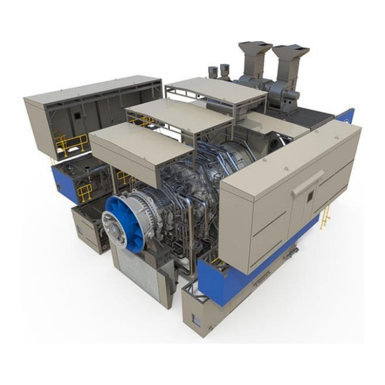
Inspection and Maintenance Guide for 7HA.02 Turbines
Dual Fuel or Gas Only Combustion Inspections
These instructions do not purport to cover all details or variations in equipment nor to provide for every possible contingency to be
met in connection with installation, operation or maintenance. Should further information be desired or should particular problems
arise which are not covered sufficiently for the purchaser's purposes the matter should be referred to General Electric Company. These
instructions contain proprietary information of General Electric Company, and are furnished to its customer solely to assist that
customer in the installation, testing, operation, and/or maintenance of the equipment described. This document shall not be reproduced
in whole or in part nor shall its contents be disclosed to any third party without the written approval of General Electric Company.
© 2020 General Electric Company. All Rights Reserved. This material may not be copied or distributed in whole or in part,
without prior permission of the copyright owner.
GE Proprietary Information - Class II (Internal) US EAR - NLR
Advertisement
Table of Contents

Related Manuals for GE 7HA.02

Summary of Contents for GE 7HA.02
- Page 1 General Electric Company. © 2020 General Electric Company. All Rights Reserved. This material may not be copied or distributed in whole or in part, without prior permission of the copyright owner. GE Proprietary Information - Class II (Internal) US EAR - NLR...
- Page 2 NOT AVOIDED WILL RESULT IN DEATH OR SERIOUS INJURY © 2020 General Electric Company. All Rights Reserved. This material may not be copied or distributed in whole or in part, without prior permission of the copyright owner. GE Proprietary Information - Class II (Internal) US EAR - NLR...
-
Page 3: Table Of Contents
Operation 31: Insulation Installation ..................43 © 2020 General Electric Company. All Rights Reserved. This material may not be copied or distributed in whole or in part, without prior permission of the copyright owner. GE Proprietary Information - Class II (Internal) US EAR - NLR... - Page 4 Figure 30: Single Wall Compressor Discharge Case Inspection Features ............35 © 2020 General Electric Company. All Rights Reserved. This material may not be copied or distributed in whole or in part, without prior permission of the copyright owner. GE Proprietary Information - Class II (Internal) US EAR - NLR...
-
Page 5: List Of Tables
No table of figures entries found. © 2020 General Electric Company. All Rights Reserved. This material may not be copied or distributed in whole or in part, without prior permission of the copyright owner. GE Proprietary Information - Class II (Internal) US EAR - NLR... -
Page 6: Disassembly Procedures
TURBINE TURNING GEAR IS EITHER STATIONARY OR RUNNING IN © 2020 General Electric Company. All Rights Reserved. This material may not be copied or distributed in whole or in part, without prior permission of the copyright owner. GE Proprietary Information - Class II (Internal) US EAR - NLR... -
Page 7: Operation 1: Remove Gt Enclosure Roof
Reference 0333 Mech Outline and MLI 1634. © 2020 General Electric Company. All Rights Reserved. This material may not be copied or distributed in whole or in part, without prior permission of the copyright owner. GE Proprietary Information - Class II (Internal) US EAR - NLR... -
Page 8: Figure 1. Enclosure Maintenance Access Ports
MLI 1634. © 2020 General Electric Company. All Rights Reserved. This material may not be copied or distributed in whole or in part, without prior permission of the copyright owner. GE Proprietary Information - Class II (Internal) US EAR - NLR... -
Page 9: Figure 2. Iso View Of Removable Roof Panels
Figure 3. Plan view of the 3 inspection roof panel sections © 2020 General Electric Company. All Rights Reserved. This material may not be copied or distributed in whole or in part, without prior permission of the copyright owner. GE Proprietary Information - Class II (Internal) US EAR - NLR... -
Page 10: Operation 2: Insulation Removal
1. Remove all insulation stud acorn nuts, nuts, and washers and store for reuse. © 2020 General Electric Company. All Rights Reserved. This material may not be copied or distributed in whole or in part, without prior permission of the copyright owner. GE Proprietary Information - Class II (Internal) US EAR - NLR... -
Page 11: Operation 3: Flame Detectors Removal Mli 1121/0915
4. Remove the flame detectors from combustion chambers 1, 10, 11 and 12. © 2020 General Electric Company. All Rights Reserved. This material may not be copied or distributed in whole or in part, without prior permission of the copyright owner. GE Proprietary Information - Class II (Internal) US EAR - NLR... -
Page 12: Operation 4: Cdm Probe Removal Mli 0726
D. Operation 4: CDM Probe Removal MLI 0726 © 2020 General Electric Company. All Rights Reserved. This material may not be copied or distributed in whole or in part, without prior permission of the copyright owner. GE Proprietary Information - Class II (Internal) US EAR - NLR... -
Page 13: Figure 8. Cdm Probe Assembly Layout
Figure 8. CDM Probe Assembly Layout © 2020 General Electric Company. All Rights Reserved. This material may not be copied or distributed in whole or in part, without prior permission of the copyright owner. GE Proprietary Information - Class II (Internal) US EAR - NLR... -
Page 14: Operation 5: Spark Plugs Removal Mli 1214
Reference Figure 10. © 2020 General Electric Company. All Rights Reserved. This material may not be copied or distributed in whole or in part, without prior permission of the copyright owner. GE Proprietary Information - Class II (Internal) US EAR - NLR... -
Page 15: Operation 6: Flex Hose Removal
CAUTION © 2020 General Electric Company. All Rights Reserved. This material may not be copied or distributed in whole or in part, without prior permission of the copyright owner. GE Proprietary Information - Class II (Internal) US EAR - NLR... - Page 16 6. Store flex hoses to prevent damage; do not stack hoses on top of one another. © 2020 General Electric Company. All Rights Reserved. This material may not be copied or distributed in whole or in part, without prior permission of the copyright owner. GE Proprietary Information - Class II (Internal) US EAR - NLR...
-
Page 17: Figure 11. Piping Arrangement - Fuel Gas
Figure 12. Gas Only Fuel Nozzle End Cover © 2020 General Electric Company. All Rights Reserved. This material may not be copied or distributed in whole or in part, without prior permission of the copyright owner. GE Proprietary Information - Class II (Internal) US EAR - NLR... -
Page 18: Operation 7: Cooling And Sealing Air Piping Removal Mli 0909
NOTE © 2020 General Electric Company. All Rights Reserved. This material may not be copied or distributed in whole or in part, without prior permission of the copyright owner. GE Proprietary Information - Class II (Internal) US EAR - NLR... -
Page 19: Figure 15. Mli 0909 Cooling And Sealing Air Piping
Figure 15. MLI 0909 Cooling and Sealing Air Piping © 2020 General Electric Company. All Rights Reserved. This material may not be copied or distributed in whole or in part, without prior permission of the copyright owner. GE Proprietary Information - Class II (Internal) US EAR - NLR... -
Page 20: Operation 8: Fuel Gas Manifold Removal Mli 0918 / 0962
1. Label False Start Drain Tubing with can number and MLI number for re-installation. © 2020 General Electric Company. All Rights Reserved. This material may not be copied or distributed in whole or in part, without prior permission of the copyright owner. GE Proprietary Information - Class II (Internal) US EAR - NLR... -
Page 21: Operation 10: Head End Module Removal Mli 0512/0513 & Mli 0722
NOTE © 2020 General Electric Company. All Rights Reserved. This material may not be copied or distributed in whole or in part, without prior permission of the copyright owner. GE Proprietary Information - Class II (Internal) US EAR - NLR... - Page 22 Do not attempt to disassemble the Head End Module. Damage to internal components may result. Complete assembly should be sent to a qualified GE Service Center for refurbishment. Reference Figure 18 - Figure 20.
-
Page 23: Figure 18. Head End Module
Figure 19. Head End Module © 2020 General Electric Company. All Rights Reserved. This material may not be copied or distributed in whole or in part, without prior permission of the copyright owner. GE Proprietary Information - Class II (Internal) US EAR - NLR... -
Page 24: Operation 11: Combustion Unibody Module Assembly And Crossfire Tube Removal Mli 0701 / 0703
0701 / 0703 NOTE Contact General Electric Company for Unibody Module and Crossfire Tube removal procedure as it requires special tooling. Refer to GE Field Services for instruction. NOTE For weight and rigging information, refer to weights and center of gravity drawing (MLI 0407) in the Reference Drawing Manual. - Page 25 © 2020 General Electric Company. All Rights Reserved. This material may not be copied or distributed in whole or in part, without prior permission of the copyright owner. GE Proprietary Information - Class II (Internal) US EAR - NLR...
-
Page 26: Figure 21. Crossfire Tube
Figure 22. Unibody Aft Bracket and Side Seal © 2020 General Electric Company. All Rights Reserved. This material may not be copied or distributed in whole or in part, without prior permission of the copyright owner. GE Proprietary Information - Class II (Internal) US EAR - NLR... -
Page 27: Inspections
Perform Borescope inspection as described in GEK 121384. © 2020 General Electric Company. All Rights Reserved. This material may not be copied or distributed in whole or in part, without prior permission of the copyright owner. GE Proprietary Information - Class II (Internal) US EAR - NLR... -
Page 28: Operation 13: Compressor Igv And Vsv Assembly Inspection
© 2020 General Electric Company. All Rights Reserved. This material may not be copied or distributed in whole or in part, without prior permission of the copyright owner. GE Proprietary Information - Class II (Internal) US EAR - NLR... -
Page 29: Electrical Shock Hazard
2, 90ESV-1, 90ESV-2) CAN RESULT IN ELECTRICAL SHOCK. © 2020 General Electric Company. All Rights Reserved. This material may not be copied or distributed in whole or in part, without prior permission of the copyright owner. GE Proprietary Information - Class II (Internal) US EAR - NLR... -
Page 30: Figure 25. Igv Configuration From Mli 4088 Schematic
Figure 25. IGV configuration from MLI 4088 Schematic © 2020 General Electric Company. All Rights Reserved. This material may not be copied or distributed in whole or in part, without prior permission of the copyright owner. GE Proprietary Information - Class II (Internal) US EAR - NLR... -
Page 31: Figure 26. Vsv Configuration From Mli 4088 Schematic
6. Visually inspect all unison ring lock nuts for thread protrusion. © 2020 General Electric Company. All Rights Reserved. This material may not be copied or distributed in whole or in part, without prior permission of the copyright owner. GE Proprietary Information - Class II (Internal) US EAR - NLR... -
Page 32: Figure 27. Typical Inspection Locations For Igv And Vsv Assemblies
Figure 27. Typical inspection locations for IGV and VSV Assemblies © 2020 General Electric Company. All Rights Reserved. This material may not be copied or distributed in whole or in part, without prior permission of the copyright owner. GE Proprietary Information - Class II (Internal) US EAR - NLR... -
Page 33: Figure 28. Inspection Locations For Igv And Vsv Unison Ring Rub Blocks
Remove controls forces previously entered. © 2020 General Electric Company. All Rights Reserved. This material may not be copied or distributed in whole or in part, without prior permission of the copyright owner. GE Proprietary Information - Class II (Internal) US EAR - NLR... -
Page 34: Operation 14: Compressor Discharge Casing (Cdc) Inspection
Single-wall CDC shown at left, Double-wall CDC shown at right. © 2020 General Electric Company. All Rights Reserved. This material may not be copied or distributed in whole or in part, without prior permission of the copyright owner. GE Proprietary Information - Class II (Internal) US EAR - NLR... -
Page 35: Figure 30: Single Wall Compressor Discharge Case Inspection Features
Figure 31: Double Wall Compressor Discharge Case Inspection Features © 2020 General Electric Company. All Rights Reserved. This material may not be copied or distributed in whole or in part, without prior permission of the copyright owner. GE Proprietary Information - Class II (Internal) US EAR - NLR... -
Page 36: Operation 15: Endcovers, Fuel Nozzles And Liquid Cartridge Inspection
Combustion Interval (operational cycle). Do not attempt to disassemble the Head End Assembly. Damage to internal components may result. Complete assembly should be sent to a qualified GE Service Center for refurbishment. E. Operation 16: Spark Plug Inspection and Test... -
Page 37: Operation 17: Flame Detector Inspection And Test
© 2020 General Electric Company. All Rights Reserved. This material may not be copied or distributed in whole or in part, without prior permission of the copyright owner. GE Proprietary Information - Class II (Internal) US EAR - NLR... -
Page 38: Operation 19: Cdm Probe Inspection
A visual inspection of the CDM probe and probe holder is required at every Combustion Inspection. 1. Inspect all the CDM probes per GEK121183. 2. Replace any damaged CDM probe hardware with GE certified parts. I. Operation 20: Combustion Unibody Module Inspection NOTE The Combustion Unibody Module is designed for inspection and refurbishment after one Combustion Interval (operational cycle). - Page 39 © 2020 General Electric Company. All Rights Reserved. This material may not be copied or distributed in whole or in part, without prior permission of the copyright owner. GE Proprietary Information - Class II (Internal) US EAR - NLR...
- Page 40 15. Use special tooling to compress each cross fire tube before installing the adjacent Unibody. © 2020 General Electric Company. All Rights Reserved. This material may not be copied or distributed in whole or in part, without prior permission of the copyright owner. GE Proprietary Information - Class II (Internal) US EAR - NLR...
-
Page 41: Operation 23: Head End Module Installation Mli 0512/0513 & Mli 0722
1. Using new gaskets connect the gas fuel lines between the flanges. © 2020 General Electric Company. All Rights Reserved. This material may not be copied or distributed in whole or in part, without prior permission of the copyright owner. GE Proprietary Information - Class II (Internal) US EAR - NLR... -
Page 42: Operation 25: Cooling And Sealing Air Piping Installation Mli 0909
1. Install new gasket. © 2020 General Electric Company. All Rights Reserved. This material may not be copied or distributed in whole or in part, without prior permission of the copyright owner. GE Proprietary Information - Class II (Internal) US EAR - NLR... -
Page 43: Operation 30: Cdm Probe Installation Mli 0726
M. Operation 34: Reassemble Turbine Compartment Roof Components © 2020 General Electric Company. All Rights Reserved. This material may not be copied or distributed in whole or in part, without prior permission of the copyright owner. GE Proprietary Information - Class II (Internal) US EAR - NLR... -
Page 44: Operation 35: Clean Up, Operate And Leak Check Unit
Check operation of the cool-down/emergency lube oil pump. © 2020 General Electric Company. All Rights Reserved. This material may not be copied or distributed in whole or in part, without prior permission of the copyright owner. GE Proprietary Information - Class II (Internal) US EAR - NLR... - Page 45 Representative. © 2020 General Electric Company. All Rights Reserved. This material may not be copied or distributed in whole or in part, without prior permission of the copyright owner. GE Proprietary Information - Class II (Internal) US EAR - NLR...
- Page 46 Maintenance Manual. It is required that tuning be done following each inspection. © 2020 General Electric Company. All Rights Reserved. This material may not be copied or distributed in whole or in part, without prior permission of the copyright owner. GE Proprietary Information - Class II (Internal) US EAR - NLR...
- Page 47 GEK121382_B © 2020 General Electric Company. All Rights Reserved. This material may not be copied or distributed in whole or in part, without prior permission of the copyright owner. GE Proprietary Information - Class II (Internal) US EAR - NLR...
Need help?
Do you have a question about the 7HA.02 and is the answer not in the manual?
Questions and answers