Table of Contents
Advertisement
Quick Links
Advertisement
Table of Contents

Related Manuals for TRENDnet TPL-305E


Summary of Contents for TRENDnet TPL-305E
-
Page 2: Table Of Contents
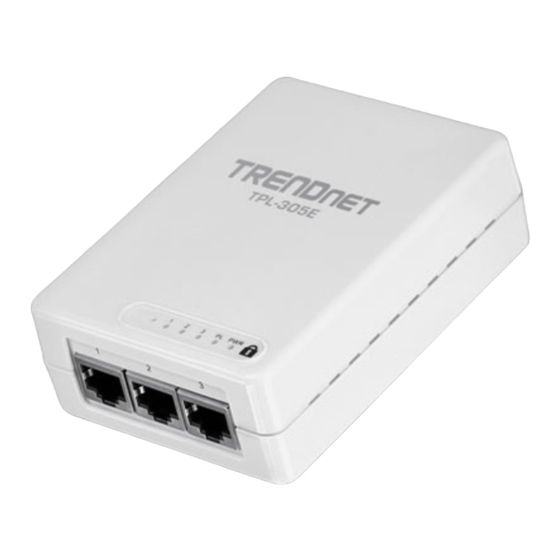
Table of Contents Chapter 1: Product Overview ................3 1.1 Powerline Network Solution ................ 3 1.2 Package Contents ..................3 1.3 System Requirements ................. 4 1.4 Device Label ....................4 1.5 LEDs ......................5 1.6 Ethernet Ports ..................... 6 Chapter 2: Product Installation ................7 2.1 Initial Installation .................. -
Page 3: Chapter 1: Product Overview
® Note: This TPL-305E 3-Port 200Mbps Powerline AV Adapter needs to pair with at least one other HomePlug compatible powerline device. (e.g. TRENDnet Powerline AV products TPL-303E, TPL-304E, TPL-310AP, or another TPL-305E.) -
Page 4: System Requirements
System Requirements CD-ROM drive A Desktop or Laptop PC with Network Adapter Installed Existing 10/100Mbps wired network when TPL-305E is used as a bridge device Additional HomePlug AV powerline adapter ® (e.g. TRENDnet TPL-303E, TPL-304E, TPL-310AP, or another TPL-305E) -
Page 5: Leds
1.5 LEDs The LED panel located on the front of the device consists of the status LEDs, Sync button, and Reset button. Powerline Link/Act LED (PL) Ethernet Link/Act LED (1-3) Power LED (PWR) Reset Button Sync Button... -
Page 6: Ethernet Ports
Color Sequence Definition Green Solid Device powered On PWR (Power) Device powered Off PL (Powerline) Solid Powerline Connected (Connection Quality is Best) Green Blinking Syncing or Powerline Data Transmitting/Receiving (Connection Quality is Best) Note: LED color Solid Powerline Connected (Connection Quality is Better) indicates the Amber strength and... -
Page 7: Chapter 2: Product Installation
TPL-305E powerline adapters, simply plug one of your TPL-305E adapters into a wall power outlet in one room and plug the other TPL-305E adapter into an available wall power outlet in another room to establish connectivity between the two rooms. -
Page 8: Initial Installation
Assuming your router is already installed and configured for Internet connectivity and the TPL- 305E powerline adapters are at factory default settings. 1. Plug one of the TPL-305E powerline adapters into an available wall power outlet in the room where your router is located. -
Page 9: Securing Your Powerline Network
Powerline Configuration Utility in Chapter 4. Note: The default network name/security key assigned to the TPL-305E is “HomePlugAV”. All powerline adapters in the same powerline network must have the same network name/security key in order to establish connectivity. If the network name/security keys are not the same for all powerline adapters on the same powerline network, the adapter will NOT establish connectivity. -
Page 10: Changing The Network Name/Security Key Using The Sync Button
Assuming your TPL-305E powerline adapters are already plugged into wall power outlets and either currently connected or disconnected to each other. 1. Push and hold the Sync button on one of the TPL-305E powerline adapters for 10 seconds and release it. -
Page 11: Adding The Powerline Adapter To An Existing Powerline Network
2.4 Adding the Powerline Adapter to an Existing Powerline Network The procedure describes how to add the TPL-305E 3-Port 200Mbps Powerline AV Adapter to an existing powerline network. Assuming the two TPL-305E powerline adapters are currently connected to each other and the third TPL-305E (Additional) powerline adapter is currently disconnected. -
Page 12: Chapter 3: Overlapping Powerline Networks
Assuming all powerline adapters are TPL-305E adapters and for reference in the diagram and this procedure, the adapters will be labeled Adapter A, B, C, D, and E. Adapters A, B, and C are currently connected together to form one powerline network and Adapters D and E form another powerline network. -
Page 13: Chapter 4: Powerline Configuration Utility
2. Before installing and using the utility, make sure your computer in which you are installing the utility is connected to your network and your TPL-305E adapters are also connected to your network. 3. Make sure all of the TPL-305E powerline adapters are already connected to each other using the procedures in Chapter 2: Product Installation. - Page 14 5. In the Setup Wizard window, click Next. 6. In the License Agreement window, click I Agree. 7. In the Install Options window, click Install.
- Page 15 8. At the Setup Wizard Completion window, click Finish. 9. The TRENDnet Powerline Configuration Utility installation window will appear automatically. At the Setup Wizard window, click Next. 10. In the License Agreement window, check the radio button I Agree, and then click Next.
-
Page 16: Using The Utility
11. In the Select Installation Folder window, click Next. 12. In the Confirm Installation window, click Next. 13. At the Installation Complete window, click Close. 4.2 Using the Utility Double-click the desktop icon to open the Powerline Configuration Utility application. - Page 17 If you have not already done so, please write down the 16-digit Device Password (DPW) and corresponding MAC Address of each TPL-305E powerline adapter as this will be required to apply changes to remote devices discovered in the utility. This is located on the Device Label, please refer to Section 1.4.
- Page 18 4. If successful, the Remote Device will have the Device Password listed next to the device under Password. Note: If the incorrect Device Password is entered, you will receive an error message. Click Enter Password and try entering the password again. 5.
-
Page 19: Chapter 5: Troubleshooting
Use a pin or paperclip and push and hold the Reset button for 1 second on each TPL-305E powerline adapter. All LEDs will turn off and turn back on. This will reset the TPL-305E powerline adapters to the default settings, network name/security key assignment “HomePlugAV”. -
Page 20: Chapter 6: Specifications
Chapter 6: Specifications Hardware Standards IEEE 802.3, IEEE 802.3x, IEEE 802.3u, HomePlug® AV Interface 3 x 10/100Mbps Auto-MDIX RJ-45 ports, Power prong Frequency Band 2 ~ 28 MHz Modulation OFDM Symbol Modulation on link synchronization, 1024/256/64/8 - QAM, QPSK, BPSK, ROBO Carrier Protocol TDMA, and CSMA/CA Speed... - Page 21 Authorization (RMA) number will be issued. An RMA number is required in order to initiate warranty service sup- port for all TRENDnet products. Products that are sent to TRENDnet for RMA service must have the RMA number marked on the outside of return packages and sent to TRENDnet prepaid, insured and packaged appropriately for safe shipment.
- Page 22 Governing Law: This Limited Warranty shall be governed by the laws of the state of California. Some TRENDnet products include software code written by third party developers. These codes are subject to the GNU General Public License ("GPL") or GNU Lesser General Public License ("LGPL").