
Related Manuals for ABB CCS Control Box NA


Summary of Contents for ABB CCS Control Box NA
- Page 1 A B B CH A R G I N G S TATI O N Operation and installation manual CCS Control Box (NA version) for HVC 200/300/360 multi-outlet cabinet...
- Page 2 Manufacturer name and address Contact ABB E-mobility USA ABB E-mobility Inc. 950 W Elliott Rd ABB E-mobility in your country can give you support on the EVSE Tempe AZ 85284 Suite 101 https://new.abb.com/ev-charging United States of America Phone: 800-825-2556 E-mail: US-evci@us.abb.com ABB E-mobility Canada ABB E-mobility Inc.
-
Page 3: Table Of Contents
Table of contents 1. Introduction and general information 4. Transport, handling and unpacking Disclaimer and warranty conditions Transport of the EVSE - Preliminary operation 4.1.1 Move the EVSE with a forklift truck Function and target of this document Unpacking Language 4.2.1 Unpacking procedure How to use this document 4.2.2 Components supplied with the EVSE... - Page 4 “Operation and installation manual” - “CCS Control Box (NA version)” 9. Maintenance and troubleshooting Maintenance schedule for the owner Troubleshooting 10. Technical data 10.1 Technical specification - CCS Control Box 10.1.1 Technical data - CCS Control Box 10.1.2 Cable specifications - CCS Control Box 10.1.3 Cable glands - CCS Control Box 10.1.4 Torque specification - CCS Control Box 10.1.5 Charging interface - CCS Control Box...
-
Page 5: Introduction And General Information
• User Disclaimer and warranty conditions ABB E-mobility shall not be liable for any damages, losses, costs or expenses resulting from the improper handling of the EVSE, in particular resulting from non compliance with the instructions of this document and other applicable regulations and standards (e.g. -
Page 6: Language
“Operation and installation manual” - “CCS Control Box (NA version)” The document is applicable to ABB E-mobility HVC (Heavy Vehicle Charger) EVSE based on the CCS charging standard: • CCS Control Box (NA version) NOTE The CCS Control Box is part of HVC systems and must be connected to the HVC 200-300-360 power cabinet. -
Page 7: Terminology
Owner of an EV, who uses the EVSE to charge the EV NOTE it is possible that not all terms are present in this document. Document revision history Version Date Description November 2023 Initial version NOTE Latest version of the manual is available online (ABB Library ID 9AKK108468A7163) -
Page 8: Safety
“Operation and installation manual” - “CCS Control Box (NA version)” 2. Safety This chapter contains the safety instructions which must obey during installation, commissioning, operation and maintenance of the equipment. Always obey and follow the reading order of instruction exactly as described in this manual to prevent injury or damage to the equipment. -
Page 9: Liability
Safety Liability The manufacturer declares that the equipment complies with the regulations currently in force in the country of installation and has issued the corresponding declaration of conformity. The manufacturer is not liable for damages, losses, costs or expenses incurred by any user of the EVSE (e.g. the installation engineer or owner of the equipment) if such damages, losses, costs or expenses result from a failure to comply with the applicable safety instructions given by the manufacturer, including, but not limited to, the following:... -
Page 10: Intended Use
“Operation and installation manual” - “CCS Control Box (NA version)” Intended use This equipment has the exclusive function of fast EV depot charging and it is intended to be used both in indoor and outdoor environments. NOTE Depot charging (overnight): truck and bus fleets that have short daily operating cycles often rely on overnight charging at the depot when a lower power can be used to charge the vehicles. -
Page 11: Residual Risks
Safety 2.2.2 Residual risks Despite the warnings and safety systems, there are still some residual risks that cannot be eliminated.These risks are listed in the following table with some suggestions to prevent them: Risk analysis and description Suggested action Noise pollution due to installation in unsuitable Reassess the environment or the place of environments or where individuals routinely work installation. -
Page 12: Symbol Description
“Operation and installation manual” - “CCS Control Box (NA version)” Symbol Description Rotating parts that can cause a risk of entrapment Hot surface that gives risk of burn injuries With signal word ‘NOTE’: A note gives more data, to make it easier to do the steps, for example Information about the condition of the EVSE before you start the procedure Requirements for personnel for a procedure General safety instructions for a procedure... -
Page 13: Personal Protective Equipment
Safety Personal protective equipment A Personal Protective Equipment (PPE) is clothing or equipment designed to protect/reduce employees from exposure to work place hazards and the risk of injury. Symbol Description Protecting clothing Safety gloves Safety shoes Safety glasses Safety instructions •... -
Page 14: Safety Instructions During Installation
“Operation and installation manual” - “CCS Control Box (NA version)” 2.5.2 Safety instructions during installation • Make sure that there are any supply voltages on the input cables during the complete installation procedure. • Keep unqualified personnel at a safe distance during installation. •... -
Page 15: Discard The Evse Or Parts Of The Evse
The manufacturer (ABB E-mobility) and its affiliates are not liable for damages and/or losses related to such security breaches, any unauthorized access, interference, intrusion, leakage and/or theft of data or information. -
Page 16: Conformity
“Operation and installation manual” - “CCS Control Box (NA version)” Conformity This manual is compliant with the following directives and applicable regulations: Standard Description UL (Underwriters Laboratories) certification FCC (Federal Communications Commission) Part 15 certification IEC 62262 International standard for impact protection rating IEC 82079-1 International Standard on information/instruction for use of products Directive 2001/95/EC... -
Page 17: Description
Description 3. Description This chapter contains information about the models, details of the equipment, characteristics and technical data, overall dimensions and equipment identification. A description of the equipment characteristics is provided to identify its main components and specify the technical terminology used in the manual. Chapter recipients: •... -
Page 18: Type Plate - Identification Of Equipment
Type plate - Identification of equipment CODE Global ID MODEL CODE Global ID Weight FOR USE WITH ELECTRICAL VEHICLES Refer to manual ABB E-Mobility B.V. Heertjeslaan 6, 2629 JG Delft, The Nederlands MADE IN ITALY Prod. date WW YYYY Ref. Description Country of origin... -
Page 19: System Overview
Description System Overview Ref. Part Function Power distribution board To supply the electrical energy to EVSE HVC 200/300/360 Power cabinet 2 or 4 outputs. Output power 200, 300 or 360 kW C1-C4 Charging interfaces installed on Available Charging Posts for connection with outputs 1-4 HVC-200/300/360 Power Cabinet Colours... -
Page 20: Depot Overview
“Operation and installation manual” - “CCS Control Box (NA version)” Depot Overview Ref. Part Function Power cabinet To change the AC input power into DC output power CCS Control Box To control the charge process The EV of which the batteries need to be charged Parking space Parking space CCS connector... -
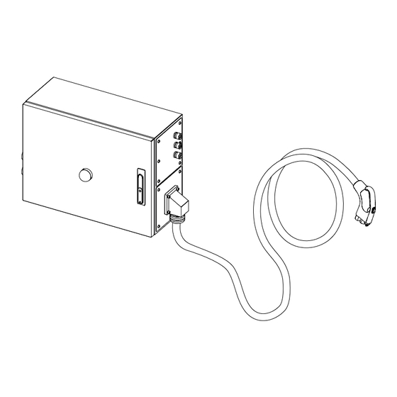
Page 21: Ccs Control Box - Overview
Description CCS Control Box - Overview 3.5.1 Overview - Outside Ref. Part Function Front door To access the internal parts of the EVSE Charging status beacon To show the EVSE status based on the colours Type plate To show the identification and technical data of the box Wall/Structure brackets To install the Control Box on a wall/roof structure Handle lock... -
Page 22: Overview - Inside
“Operation and installation manual” - “CCS Control Box (NA version)” 3.5.2 Overview - Inside Ref. Part Function Protection barrier. If opened, it allows access to the Internal flip cover internal connection and components Cable conduits To arrange and protect the cables inside the box DC SPD DC lines surge protection device DC SPD fuses... - Page 23 Description Standard communication line between Control Box X2, X3 Ethernet connectors and HVC-200/300/360 Power Cabinet Optional “Long distance kit” To convert the communication line from Ethernet to components (Ethernet to fiber optic fiber converter and relay) Internal flip cover fasten points To lock in place the internal flip cover Ref.
-
Page 24: Overview - Cable Glands
“Operation and installation manual” - “CCS Control Box (NA version)” 3.5.3 Overview - Cable glands Ref. Part Function Ext. Emergency button The cable gland is equipped with a multientry gasket that Ext. LED Tower Lights allows to seal till 3 cables (External Emergency button, LED Ext. -
Page 25: Evse Status Beacon
Description EVSE status beacon The EVSE is equipped with a beacon on the front of the box, that indicates the status based on the colours. In the table are described the main status: LEDs color Description The EVSE is in idle mode and ready for use: The beacon of the EVSE is solid green The EVSE is in waiting/getting ready to charge:... -
Page 26: Working Principles
“Operation and installation manual” - “CCS Control Box (NA version)” Working principles Colours Description Bold lines: power connection Thin lines: auxiliary power connection Ethernet line Control signal or monitoring signal CAN bus... -
Page 27: Optionals
Description Optionals 3.9.1 External LED Tower lights A LED Tower lights can be installed externally to view and check the EVSE status from different positions without having to check the beacon on the box itself. Each signal tower module is equipped with a bayonet fixing with integral contact system. The modules are fastened together by aligning the corresponding white marks then with a gentle twist they are locked into place. -
Page 28: External Emergency Stop Button
“Operation and installation manual” - “CCS Control Box (NA version)” 3.9.2 External Emergency stop button The external Emergency stop button (EMO) is used to stop the charge session in case of an emergency (the beacon will become red). The Emergency stop button is equipped with 2 contacts normally closed (NC) Ref. - Page 29 Description Ref. Part Function ABB6AGC084183 Global ID of Long Distance Kit DIN rail Where to install the kit components Ethernet connector Ethernet connector of Control Box CCB (Core Control board) To supply the kit components Relay K1 Relay to power supply the Ethernet to fiber converter DIN rail end stop To lock the DIN rail components in place Fiber optic connectors (B-FOC type)
-
Page 30: Cable Balancer
“Operation and installation manual” - “CCS Control Box (NA version)” 3.9.5 Cable balancer For depot applications where charger footprint is limited, we provide control boxes that can be ceiling mounted to avoid chargers being installed on the ground. For such use cases, cable management also becomes essential for easy usability of the CCS charging cable and connector. -
Page 31: Transport, Handling And Unpacking
Transport, handling and unpacking 4. Transport, handling and unpacking In this section are explained all the transport specification, including handling and unpacking procedures of the EVSE. Chapter recipients: • Owner • Installer... -
Page 32: Transport Of The Evse - Preliminary Operation
“Operation and installation manual” - “CCS Control Box (NA version)” Transport of the EVSE - Preliminary operation A transport company delivers the EVSE close to the site. The movement of the EVSE to its final location is their responsibility. NOTE If you need to store the equipment before installation, obey the ambient conditions for storage. -
Page 33: Move The Evse With A Forklift Truck
Transport, handling and unpacking 4.1.1 Move the EVSE with a forklift truck • Move the forks of the forklift truck in the gaps of the pallet. WARNING Risk of pinching or crushing, the equipment is heavy • Obey the safety instructions that apply to the forklift truck. •... -
Page 34: Components Supplied With The Evse
• Make sure that all parts are delivered according to the order. • If you find damage or the parts are not according to the order, contact the local representative of the manufacturer (ABB EV Infrastructure). 4.2.2 Components supplied with the EVSE... -
Page 35: Access To The Internal Parts
Access to the internal parts 5. Access to the internal parts In this section are illustrated all the acces procedures. Chapter recipients: • Installer... -
Page 36: Access To The Internal Parts - Ccs Control Box
“Operation and installation manual” - “CCS Control Box (NA version)” Access to the internal parts - CCS Control Box Hazardous voltage Make sure that only qualified persons have access to the door key. NOTE There is one unique door key for the Control Box. 5.1.1 Open the lock of the door - CCS Control Box •... -
Page 37: Close The Doors - Ccs Control Box
Access to the internal parts Unscrew the bolts on the 6 internal latches on the lower internal part of the EVSE and extract the cover. 5.1.3 Close the doors - CCS Control Box Hazardous voltage Make sure that only qualified persons have access to the door key. NOTE There is one unique door key for each cabinet. -
Page 38: Installation
“Operation and installation manual” - “CCS Control Box (NA version)” 6. Installation In this section are illustrated all the installation procedure. Chapter recipients: • Owner • Installer Wall/Structure installation of the Control Box The installation of the Control Box can be done on a wall or roof structure: NOTE This type of installation can be done using the supplied wall brackets. -
Page 39: Wall Space Requirements
Installation 6.1.1 Wall space requirements Font view Top view Parameter Description Specification [mm] Space to route the cables inside the box Space to route the cables inside the box Space to install, open and maintain the equipment 1000 Space to install the equipment up to the floor in correspondence Space to route the charging cable to the EV of the charging cable... -
Page 40: Install The Control Box On The Wall/Structure
“Operation and installation manual” - “CCS Control Box (NA version)” 6.1.3 Install the Control Box on the wall/structure • Mark the 4 fastening points using the following measurements as a drilling template Parameter Description Specification [mm] Space between the two holes of the brackets (vertically installed) Space between the two holes of the brackets (vertically installed) 508,6 •... -
Page 41: Electrical Connection
Electrical connection 7. Electrical connection In this section are listed all the electrical connection procedure. Chapter recipients: • Installer... -
Page 42: Electrical Installation Of Ccs Control Box
“Operation and installation manual” - “CCS Control Box (NA version)” 7.1 Electrical installation of CCS Control Box 7.1.1 Protective earth (PE) connection HAZARDOUS VOLTAGE Before carrying out any operation, check that any external switch of voltage sources (downstream to the EVSE) are in OFF position and check for input voltage absence! The Protective Earth (coming from the Power Cabinet) must be connected to point marked with the protective earth symbol and using a cable with an appropriate conductor cross-section for the maximum ground fault Up to 150 meters away... - Page 43 Electrical connection NOTE Any failure of the EVSE not connected to PE is not covered by the warranty. In compliance with standards it is necessary to install a earthing cable in one of the protective earth terminal with a minimum section as indicated in the table below: Cable Cross section PE (Yellow/Green)
-
Page 44: Dc Auxiliary Connection
“Operation and installation manual” - “CCS Control Box (NA version)” 7.1.2 DC auxiliary connection The DC auxiliary power supply is supplied by the dedicated 24V DC output of HVC-200/300/360 Power Cabinet. Power cabinet Control box CCS HVC-200/300/360 24V DC Power Supply 24V DC Power Supply Cable ferrule 6 mm... -
Page 45: Dc Input Power Connection
Electrical connection • Cut the DC cable to the correct length to reach the X1 screw terminal blocks. NOTE The cable inside the cable duct must not be too tight. • Strip the insulation and crimp a ferrule on the positive pole (C) and negative pole (B). - Page 46 “Operation and installation manual” - “CCS Control Box (NA version)” • Open the box and remove the lower internal protective cover. Refer to “5.1. Access to the internal parts - CCS Control Box”. • Unscrew and remove the rings of the DC power input cable glands (D) and (E).
-
Page 47: Interlock And Dc Guard Connection
Electrical connection 7.1.4 Interlock and DC Guard connection The interlock and the DC guard are two control systems that work interconnected with each other. • The system interlock is a current loop that runs between all devices of the system (in this case the Power Cabinet and the CCS Control Box). - Page 48 “Operation and installation manual” - “CCS Control Box (NA version)” • Open the box and open the internal flip protective cover. Refer to “5.1. Access to the internal parts - CCS Control Box”. • Unscrew and remove the rings of the DC power input cable gland (H).
-
Page 49: Ethernet Connection
If an on-site internet connection is available, the charger will be automatically configured to transmit telemetry data to the ABB EVCI Cloud without the need to install any additional devices (the logging functionality is already integrated into the charger by default). ABB’s EVCI cloud platform consists of several solutions for monitoring and management of chargers in real-time. - Page 50 “Operation and installation manual” - “CCS Control Box (NA version)” • Cut the Ethernet cable (from the Power Cabinet) to the correct length to reach the X2 connector. The wire must be route inside the cable ducts. NOTE The cable inside the cable duct must not be too tight.
-
Page 51: External Stop Button, Emergency Button And Led Tower Lights Connection (Optional)
Electrical connection External Stop button, Emergency button and LED Tower lights connection (optional) The connection of the external optional devices must be made on X1 (B) connector passing the cable through the cable gland (A). Connection specifications 0.22 ... 4 mm² wire with non insulated ferrule X1 _ Connecting capacity 0.22 ... - Page 52 “Operation and installation manual” - “CCS Control Box (NA version)” • Cut the cables to the correct length to reach the X1 screw terminal blocks. The wire must be route inside the cable duct. NOTE The cable inside the cable duct must not be too tight.
-
Page 53: Installation Of Long Distance Kit (Optional)
Electrical connection Installation of Long distance kit (optional) In case of installations with distance more than 100 m between Power Cabinet and CCS Control Box, the Long distance communication kit, based on a fiber optic communication line, can be used. When using this kit, ethernet cable between Cabinet and charge post is replaced by glass fiber cable. -
Page 54: Install The Long Distance Kit
“Operation and installation manual” - “CCS Control Box (NA version)” Please note that the fiber optic cable must pass through the M32 gland installed on the Control Box. In alternative: • Order a fiber optic cable with M32 gland assembled on it. •... - Page 55 Electrical connection • Take the wiring harness X3-1 K4-11 indicated and connect it as X3-3 indicated in the picture . ETH to fiber converter X-11 or X12_Depot charge box Ethernet connector X3-1 K4-11 X3-3 K1-11_Interface relay-bottom side X3-3 (US2)_ ETH to fiber converter X3-1 (US1)_ ETH to fiber converter X3-2 (GND)_ ETH to fiber converter J5_CCB2 board...
- Page 56 “Operation and installation manual” - “CCS Control Box (NA version)” ETH to fiber converter X-11 or X12_Depot charge box Ethernet connector • Take the wiring harness indicated and connect it as indicated in the picture . K1-11_Interface relay-bottom side X3-3 (US2)_ ETH to fiber converter X3-2 X3-2 K4-12...
- Page 57 Electrical connection • Insert the fiber optic cable through the cable gland (I). • Remove the protection covers from the optical connectors. • Connect the two fiber cables - Rx. Connect it with Tx coming from power cabinet. - Tx. Connect it with Rx coming from power cabinet.
-
Page 58: Hvc 200/300/360 Reconfiguration For Long Distance Kit
“Operation and installation manual” - “CCS Control Box (NA version)” 7.3.5 HVC 200/300/360 reconfiguration for Long distance kit In order to ensure the communication, using the Long distance kit, the following operation must be performed on the HVC 200/300/360 power cabinet. •... -
Page 59: Ethernet Connectors
Electrical connection • Connect the cable(s) (previously removed from the ARM XL board) to the Ethernet connectors installed on the DIN rail. See table below: -X84 From Ethernet ARM XL board connectors -X85 socket CB4B (Outlet 1) -X84 (-X4:8) socket CB4A (Outlet 2) -X85 (-X5:8) socket CB3B (Outlet 3) -X86 (-X6:8) -
Page 60: Operation And Correct Use
“Operation and installation manual” - “CCS Control Box (NA version)” 8. Operation and correct use This chapter will give instruction on the correct use of the EVSE. Chapter recipients: • Owner • Installer • User... -
Page 61: Prepare For Commissioning
4G LTE bands 2 (1900 MHz), 4 (1700/2100MHz), or 12 (700 MHz). NOTE The Charger supports SIM cards provided by ABB only. Any other types of SIM cards are not supported. The signal strength must be greater than -85 dBm and should be measured with a cellular network signal meter. -
Page 62: Prepare Before Use
“Operation and installation manual” - “CCS Control Box (NA version)” Prepare before use • Appoint a site operator and an installation engineer, if these are other persons than you. • Make sure that the EVSE is installed according to the instructions in Operation and installation manual.. •... -
Page 63: Stop A Charge Session
Operation and correct use 8.3.2 Stop a charge session NOTE The charge session will automatically stop after completing the bulk charge mode (standard setting is 99% for this setup but can be customized). • To manually stop a charge session an external stop button connected to the Control Box should be installed. Otherwise the charging session can be stopped by the Electrical Vehicle control panel. -
Page 64: Maintenance And Troubleshooting
“Operation and installation manual” - “CCS Control Box (NA version)” 9. Maintenance and troubleshooting In this section the user will be istructed on maintenance and cleaning procedures. Preliminary requirements Owner... -
Page 65: Maintenance Schedule For The Owner
Maintenance and troubleshooting Maintenance schedule for the owner Frequency Task Procedure Clean: • Cleaning agent with pH value between 6 and 8 • Remove dirt by hand. Do not use abrasive tools. • Remove rough dirt by rinsing with tap water. Do not apply high-pressure water jets. -
Page 66: Technical Data
“Operation and installation manual” - “CCS Control Box (NA version)” 10. Technical data This chapter contains information about the models, details of the equipment, characteristics and technical data, overall dimensions and equipment identification. A description of the equipment characteristics is provided to identify its main components and specify the technical terminology used in the manual. -
Page 67: Technical Specification - Ccs Control Box
Technical data 10.1 Technical specification - CCS Control Box 10.1.1 Technical data - CCS Control Box CCS Control Box Product information and main features Depot charging (Overnight) Opportunity charging CCS cable integrated Sequential charging Optional Accessory Cable balancer DC Auxiliary Power supply Input connection 1x positive, 1x negative 24V DC (coming from HVC360 power cabinet or external... -
Page 68: Cable Specifications - Ccs Control Box
“Operation and installation manual” - “CCS Control Box (NA version)” 10.1.2 Cable specifications - CCS Control Box NOTE • All cables must be resistant to being placed in the ground using conduit. • All cables must have and isolation that are self-extinguishing and flame retardant according to IEC 60332-1-2. -
Page 69: Cable Glands - Ccs Control Box
Technical data 10.1.3 Cable glands - CCS Control Box Clamping Ref. Part Torque [Nm] range [mm] Ext. Emergency button / Ext. LED Tower Lights /Ext. Charge Stop 13...18 5 Nm button Ethernet 13...18 5 Nm Spare 5...10 DC- In 22...32 10Nm DC+ In 22...32... -
Page 70: Charging Interface - Ccs Control Box
“Operation and installation manual” - “CCS Control Box (NA version)” 10.1.5 Charging interface - CCS Control Box Charging interface Max. Voltage capability [V] Max. current capability [A] CCS1 (air cooled) 1.000V DC 200 A DC... -
Page 71: Attachments
Attachments 11. Attachments In this section additional tecnical drawing, specification, schematics are given. NOTE If you need further information, please contact your local manufacturer service dept. Refer to section “Manufacturer and contact data”... -
Page 72: Overall Dimensions
“Operation and installation manual” - “CCS Control Box (NA version)” 11.1 Overall dimensions 11.1.1 CCS Control Box Overall dimensions of CCS Control Box. NOTE The dimensions are expressed in millimeters. -
Page 73: External Led Tower Lights
Attachments 11.1.2 External LED Tower Lights NOTE The dimensions are expressed in millimeters. Ø Ø... -
Page 74: Connection Diagram
“Operation and installation manual” - “CCS Control Box (NA version)” 11.2 Connection diagram The connection diagram shows all necessary and optional connections of the CCS Control Box. - Page 75 — https://new.abb.com/ev-charging...
Need help?
Do you have a question about the CCS Control Box NA and is the answer not in the manual?
Questions and answers