Advertisement
Advertisement
Table of Contents

Related Manuals for EKF APD-32

Summary of Contents for EKF APD-32
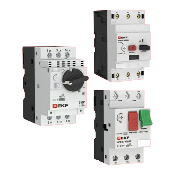
- Page 1 TECHNICAL MANUAL Motor starters APD-32, APD-80, GV2P EKF...
-
Page 2: Technical Data
1 DESCRIPTION The motor starters APD-32, APD-80, GV2P with thermomagnetic release are designed for switching AC circuits with voltages up to 690 V and 50/60 Hz frequency, and for control and protection of three-phase asynchronous motors against overload, phase loss, and short-circuit. - Page 3 Thermal Setpoint adjustment Category АС-3, 50/60 Hz release setpoint range of thermal current, A release Ir, А 380/415 V 500 V 690 V Motor starters APD-32, GV2P 0,16 0,1 – 0,16 0,02 0,03 0,04 0,25 0,16 – 0,25 0,06 0,08 0,11 0,25 –...
-
Page 4: Tripping Characteristics
A Icu kА Ics % kА Icu kА Ics % kА Icu kА Ics % kА Motor starters APD-32, GV2P 4 – 6,3 6 – 10 9 – 14 13 – 18 17 – 23 20 – 25 24 – 32 Motor starters APD-80 16 –... - Page 5 Undervoltage release (RMN) and shunt release (RN) Voltage, V Name operating voltage Insulation Hold voltage Release voltage at 50 Hz voltage Ui Motor starters APD-32, GV2P APD-32-RMN-11 220-240 (0,85...1,1) Un (0,8...0,35) Un APD-32-RMN-11 220-240 (0,7...1,1) Un (0,65...0,2) Un Motor starters APD-80...
-
Page 6: Wiring Diagrams
Insulation voltage Max. number Thermal resistance Name Mounting type Type of contacts Ui, V per APD current Ith, A APD-32-DK-11 on the left side of the APD APD-32-AK-1001 NO+NC in the front, above APD-32-BK-11 control 3.1 WIRING DIAGRAMS Table 6... - Page 7 4 INSTALLATION AND OVERALL DIMENSIONS APD-32 APD32-D, RMN APD32-VK, VKI APD32-VK APD32-PVK Fig. 2 GV2P 44,5 x1 – minimum distance between live parts (ICS max.) 40 mm for Ue 415 V 80 mm for Ue = 440 V 120 mm for Ue = 500, 690 V x2 = 40 mm Fig.
- Page 8 APD-80 х1 – minimum distance between live parts (ICS max) 40 mm for Ue < 500 V 50 mm for Ue < 690 V Fig. 4 POSITION IN SPACE Motor starters shall be mounted and connected by qualified electrical personnel. Motor starters shall be mounted onto 35mm DIN rail.
-
Page 9: Safety Requirements
Service life: 10 years. Manufacturer: OOO Electroresheniya, Otradnaya st., 2b/9, 127273, Moscow, Russia, tel. +7 (495) 788-88-15. MEA regional headquarters: EKF ELECTRICAL SOLUTION FZCO, Office 249, Techno Hub-2, Dubai Silicon Oasis, P.O. box 341079, Dubai, United Arab Emirates, tel. +9 (714) 547-06-18.
Need help?
Do you have a question about the APD-32 and is the answer not in the manual?
Questions and answers