Table of Contents
Advertisement
Quick Links
Advertisement
Table of Contents

Related Manuals for Vaisala WXT530 Series


Summary of Contents for Vaisala WXT530 Series
- Page 1 M211840EN-G User Guide Vaisala Weather Transmitter WXT530 Series...
- Page 2 English versions are This product contains software developed applicable, not the translations. by Vaisala or third parties. Use of the The contents of this document are subject software is governed by license terms and to change without prior notice.
-
Page 3: Table Of Contents
Table of contents Table of contents About this document................... 13 Version information..................13 Related manuals....................13 Documentation conventions................14 Trademarks.......................14 Product overview...................15 WXT530 Series weather transmitters............15 2.1.1 WXT536..................... 17 2.1.2 WXT535 and WXT534................18 2.1.3 WXT533 and WXT532................18 2.1.4 WXT531......................19 Components.................... - Page 4 WXT530 Series User Guide M211840EN-G Installing Vaisala Configuration Tool............49 Installing USB cable driver................50 Power management..................53 Power supplies....................53 Power management..................56 Wiring with 8-pin M12 connector..............59 5.3.1 External wiring..................59 5.3.2 Internal wiring..................62 Wiring with screw terminals................. 65 Data communication interfaces..............68 Connection options..................
- Page 5 Table of contents 7.3.7 Start concurrent measurement (aC)............ 96 7.3.8 Start concurrent measurement with CRC (aCC)......... 97 7.3.9 Send data command (aD)..............98 7.3.10 Examples of aM, aC and aD commands..........99 7.3.11 Continuous measurement (aR).............101 7.3.12 Continuous measurement with CRC (aRC)........102 NMEA 0183 v3.0 protocol................
- Page 6 WXT530 Series User Guide M211840EN-G Analog output....................141 8.7.1 Analog output operation............... 141 8.7.2 Analog output scaling................142 8.7.3 Analog output signal for wind speed channel........143 8.7.4 Analog output signal for wind direction channel......143 8.7.5 Enabling or disabling analog output...........144 Maintenance....................
- Page 7 Table of contents Modbus configuration.................. 186 B.5.1 Updating WXT530 firmware..............186 B.5.2 Changing from CLI mode to Modbus mode........187 B.5.3 Changing from Modbus mode to CLI mode........187 B.5.4 Changing port settings................. 188 B.5.5 Changing Modbus address in CLI mode..........189 B.5.6 Using Modbus with old WXT530............
- Page 8 Termination jumper positions..............69 Figure 24 Service cable connection................72 Figure 25 Analog input connector pins..............135 Figure 26 Analog input settings in Vaisala Configuration Tool......136 Figure 27 WXT531 dimensions..................161 Figure 28 WXT533 and WXT532 dimensions............162 Figure 29 WXT535 and WXT534 dimensions............163 Figure 30 WXT536 dimensions..................
- Page 9 List of figures Figure 40 Wind measurement averaging method..........201 Figure 41 Complete set of accessories..............205 Figure 42 WXT536 with surge protector WSP150..........206 Figure 43 WXT536 with surge protector WSP152..........207...
-
Page 10: List Of Tables
Table 11 Standby power consumption................ 56 Table 12 Economic power management..............58 Table 13 Pinouts for WXT530 series serial interfaces and power supplies..60 Table 14 Screw terminal pinouts................... 60 Table 15 WXT532 mA output option screw terminal pinouts........ 61 Table 16 RS-232 wiring.....................62... - Page 11 List of tables Table 45 Air temperature measurement performance.......... 154 Table 46 Relative humidity measurement performance........154 Table 47 Precipitation measurement performance..........155 Table 48 Wind measurement performance...............155 Table 49 Inputs and outputs..................156 Table 50 WXT536 analog input options..............157 Table 51 WXT530 analog mA output options............
- Page 12 WXT530 Series User Guide M211840EN-G...
-
Page 13: About This Document
Table 2 Related manuals Document code Name M211974EN Vaisala WXT536 Weather Parameter Hub Quick Guide M212051EN Updating WXT530 Series Software through RS-485 or RS-232 Data Port Technical Note M212053EN Updating WXT530 Software through Service Port Technical Note M212492EN Replacing WXT530 Series Bottom Assembly... -
Page 14: Documentation Conventions
Lists tools needed to perform the task. Indicates that you need to take some notes during the task. 1.4 Trademarks Vaisalaâ, BAROCAPâ, HUMICAPâ, RAINCAPâ, and WINDCAPâ are registered trademarks of Vaisala Oyj. Microsoftâ and Windowsâ are either registered trademarks or trademarks of Microsoft Corporation in the United States and other countries. -
Page 15: Product Overview
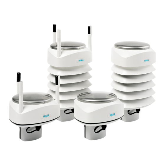
2.1 WXT530 Series weather transmitters WXT531 WXT533 WXT535 WXT536 WXT532 WXT534 The WXT530 series transmitters are suitable for several purposes, such as: • Agro-meteorological applications • Building control systems • Cruisers • Energy applications • Environmental monitoring • Fire weather • Meteorological test beds •... -
Page 16: Table 3 Wxt530 Series Features
WXT530 Series User Guide M211840EN-G Table 3 WXT530 series features Feature Value / Description Transmitter power-up 5 … 32 V DC Communication protocols • SDI-12 • ASCII automatic and polled • NMEA 0183 with query option • Modbus RTU Serial interface options •... -
Page 17: Wxt536
Chapter 2 – Product overview 2.1.1 WXT536 Table 5 WXT536 measurements Sensor Pressure Temperature Humidity Rain Wind speed Wind direction WXT536 ✓ ✓ ✓ ✓ ✓ ✓ WXT536 offers an analog input option. Figure 1 WXT536 Analog input option Analog input option not ordered... -
Page 18: Wxt535 And Wxt534
WXT530 Series User Guide M211840EN-G 2.1.2 WXT535 and WXT534 Table 6 WXT534 and WXT535 measurements Sensor Pressure Temperature Humidity Rain Wind speed Wind direction WXT535 ✓ ✓ ✓ ✓ WXT534 ✓ ✓ ✓ Figure 2 WXT535 and WXT534 2.1.3 WXT533 and WXT532 Table 7 WXT533 and WXT532 measurements... -
Page 19: Wxt531
Chapter 2 – Product overview WXT532 offers an mA output option. Figure 3 WXT533 and WXT532 2.1.4 WXT531 Table 8 WXT531 measurements Sensor Pressure Temperature Humidity Rain Wind speed Wind direction WXT531 ✓... -
Page 20: Components
WXT530 Series User Guide M211840EN-G Figure 4 WXT531 2.2 Components Figure 5 WXT536 components Fixing screw and chassis grounding point Screw cover Top of the transmitter Radiation shield Bottom of the transmitter... -
Page 21: Figure 6 Cut-Away View Of Wxt536
Chapter 2 – Product overview Figure 6 Cut-away view of WXT536 Wind transducers (3 pcs) Precipitation sensor Pressure sensor inside the PTU module Humidity and temperature sensors inside the PTU module Service port... -
Page 22: Optional Features
8-pin M12 connector for power or data cable Alignment direction indicator arrow Fixing screw and chassis grounding point 2.3 Optional features The WXT530 series includes the following optional features: • USB cables • Mounting kit • Bird kit • Vaisala Configuration Tool •... -
Page 23: Usb Cables
Chapter 2 – Product overview More information ‣ Options and accessories (page 166) 2.3.1 USB cables The service cable, while connected between the service port and PC, forces the service port to RS-232 / 19200, 8, N, 1. You need a driver for the USB cable. More information ‣... -
Page 24: Mounting Kit
WXT530 Series User Guide M211840EN-G 2.3.2 Mounting kit The optional mounting kit (212792) helps mounting the transmitter on a pole mast. If you use the mounting kit, you only need to align the transmitter when mounting for the first time. With the mounting kit, WXT530 IP rating is IP66. Without the mounting kit, the rating is IP65. -
Page 25: Surge Protector
• Vaisala Surge Protector WSP150. A compact transient overvoltage suppressor designed for outdoor use. It can be used with all Vaisala wind and weather instruments. Install WSP150 close to the protected instrument (maximum 3 m). • Vaisala Surge Protector WSP152. -
Page 26: Bird Kit
WXT530 Series User Guide M211840EN-G 2.3.4 Bird kit The optional bird kit reduces the interference that birds cause to the wind and rain measurement. The kit consists of a metallic band with spikes pointing upward. The kit is installed on top of the transmitter. -
Page 27: Vaisala Configuration Tool
When the kit is in place, more snow can accumulate on the transmitter, and the snow can melt away more slowly. 2.3.5 Vaisala Configuration Tool Vaisala Configuration Tool is a Windows-based, user-friendly parameter setting software for WXT530 transmitters. It is also fully compatible with WMT52 and WXT520. Figure 9 Vaisala Configuration Tool 2.3.6 Sensor heating... -
Page 28: Backward Compatibility
WXT530 with the latest version of Vaisala Configuration Tool . Because the WXT530 series has several product variants, the old configuration code does not apply to the new WXT530 sensor. You must generate and apply a new order code for it. - Page 29 Chapter 2 – Product overview • Increase the separation between the equipment and receiver. • Connect the equipment into an outlet on a circuit different from that to which the receiver is connected. • Consult the dealer or an experienced radio/TV technician for help. CAUTION! This unit was tested with shielded cables on the peripheral devices.
-
Page 30: Functional Description
✔ ✔ The transmitters use Vaisala WINDCAP sensor technology for wind measurement. The wind sensor has an array of 3 equally spaced ultrasonic transducers on a horizontal plane. The unit determines wind speed and wind directions by measuring the time it takes the ultrasound to travel from one transducer to the other two. -
Page 31: Precipitation Measurement Principle
✔ ✔ ✔ The transmitter uses Vaisala RAINCAP Sensor 2 technology in precipitation measurement. The precipitation sensor comprises of a steel cover and a piezoelectrical sensor mounted on the bottom surface of the cover. The precipitation sensor detects the impact of individual raindrops. The signals from the impact are proportional to the volume of the drops. -
Page 32: Ptu Measurement Principle
WXT530 Series User Guide M211840EN-G Precipitation current intensity is internally updated every 10 seconds and represents the intensity during the 1-minute period before requesting/automatic precipitation message sending (for fast reactions to a rain event, during the first minute of the rain event, the intensity is calculated over the period rain has lasted in 10-second steps instead of a fixed period of 1 minute). -
Page 33: Heating
Chapter 3 – Functional description In case of capacitive sensors, the measurement principle of the transmitter is based on an advanced RC oscillator and reference capacitors against which the capacitance of a sensor is continuously measured. The resistive Pt1000 sensors are measured with a voltage divider circuit incorporating a reference resistor and a stable voltage source. -
Page 34: Analog Input Interface
WXT530 Series User Guide M211840EN-G More information ‣ Supervisor message (page 131) 3.5 Analog input interface WXT536 WXT535 WXT534 WXT533 WXT532 WXT531 ✔ WXT536 offers an analog input option for solar radiation, external temperature, level measurement, and tipping bucket. Tipping bucket and level sensor are not supported by the Modbus protocol. -
Page 35: Installation
Teflon paste, between different kinds of metal. 4.1.1 Maritime installations In maritime installations according to IEC 60945, the WXT530 series belongs to the installation category C, which means that it is exposed to weather. When making maritime installations, note the following: •... - Page 36 Additional protection is needed in regions with frequent, severe thunderstorms, especially when long line cables (> 30 m / 98 ft ) are used. Vaisala recommends using a surge protector, such as WSP150 and WSP152, in all sites with an...
-
Page 37: Unpacking Wxt530
Chapter 4 – Installation 4.3 Unpacking WXT530 The transmitter comes in a custom protective package. The following figure shows the contents of the package. Figure 11 Package contents Protective packaging top Shipping carton Inner box Manual, cables, mounting kit (optional) Installation note Protective packaging bottom Transmitter Bird kit (optional) - Page 38 WXT530 Series User Guide M211840EN-G CAUTION! Be careful not to damage the wind transducers located at the top of the 3 antennas. Dropping the device can break or damage the transducers. If the antenna bends or twists, re-aligning can be difficult or impossible.
-
Page 39: Mounting Wxt530
Chapter 4 – Installation 4.4 Mounting WXT530 The transmitter is easy to install as it does not have any moving parts. The transmitter can be mounted on: • Vertical pole mast • Support arm Install the transmitter upright. The transmitter radiation shield reflects light. If you install the transmitter next to a pyranometer, the pyranometer can give incorrect measurements. - Page 40 WXT530 Series User Guide M211840EN-G 1. Remove the screw cover and insert the transmitter to the pole mast. 2. Align the transmitter so that the arrow points to North. 3. Tighten the fixing screw and replace the screw cover. 4. Connect the sensor cable.
-
Page 41: Mounting Wxt530 On Vertical Pole Mast With Mounting Kit
Chapter 4 – Installation 4.4.2 Mounting WXT530 on vertical pole mast with mounting 2.5‑mm and 5‑mm Allen keys CAUTION! Handle with care. Any impact on the instrument or sensor array may cause damage and lead to incorrect measurements. When mounting a transmitter on a pole mast, you can use an optional mounting kit to ease mounting. - Page 42 WXT530 Series User Guide M211840EN-G 5. Holding the sensor from its body, run the sensor cable through the mounting adapter, and slide the sensor onto the adapter. Do not tighten the fixing screw yet. Fixing screw Mounting accessory between mounting kit and 60 mm tube...
-
Page 43: Mounting Wxt530 On Sensor Support Arm
Chapter 4 – Installation 8. Remove the protective cushion. When removing a transmitter from the pole, turn the transmitter so that it snaps out from the mounting kit. Realignment is not needed when replacing the device. 4.4.3 Mounting WXT530 on sensor support arm 10‑mm wrench If you use the optional mounting kit, you only need to align the sensor when mounting it for the first time. - Page 44 WXT530 Series User Guide M211840EN-G 3. Mount the transmitter on the sensor support arm. Nut M6 DIN 934 Mounting bolt M6 DIN 933 Screw cover Mounting bolt M6 DIN 933 Nut M6 DIN 934...
-
Page 45: Grounding
Chapter 4 – Installation 4.5 Grounding A transmitter is typically grounded by installing it on a mast or a cross arm that provides a good connection to earth ground. As grounding is provided through the fixing screw (or mounting bolt), it is important that it makes a good ground connection. -
Page 46: Aligning Wxt530
WXT530 Series User Guide M211840EN-G 4. Insert the grounding kit through the hole in the seal. Make sure that the nuts are tight so that the connector has a good connection. Seal Fixing screw 5. Connect the other end of the cable to a good grounding point. -
Page 47: Figure 12 Wxt530 North Arrow
Chapter 4 – Installation Figure 12 WXT530 North arrow Wind direction can be referred either to true North, which uses the Earth’s geographic meridians, or to the magnetic North, which is read with a magnetic compass. The magnetic declination is the difference in degrees between the true North and magnetic North. The source for the magnetic declination should be current as the declination changes over time. -
Page 48: Aligning Wxt530 With Compass
WXT530 Series User Guide M211840EN-G Figure 13 Magnetic declination True North Magnetic North Declination 4.6.1 Aligning WXT530 with compass • 2.5‑mm Allen key • Compass Do not remove the instrument or sensor from the mounting kit during alignment. 1. If the transmitter is mounted, loosen the fixing screw on the bottom of the transmitter so that you can rotate it. -
Page 49: Installing Vaisala Configuration Tool
‣ Mounting WXT530 on sensor support arm (page 43) 4.7 Installing Vaisala Configuration Tool 1. Insert the WXT530 driver memory stick in the USB port. 2. Go to the WXT_Series_Conf_Tool folder and run WXTConf-2.41 r.3Setup.exe. 3. When Vaisala Configuration Tool Setup Wizard opens, select Next. -
Page 50: Installing Usb Cable Driver
7. In the Select Additional Tasks window, select Additional Tasks and select Next. 8. In the Ready to Install window, select Install. Installing window opens. 9. Select Launch Vaisala Configuration Tool and select Finish to launch the tool. More information ‣... - Page 51 6. Select Display Vaisala USB Device Finder > Finish. The driver starts. Newer Windows versions might require checking the driver status by opening Windows Device Manager. It should have Vaisala USB Device listed under Ports (COM & LPT). 7. Connect the cable.
- Page 52 There is no reason to uninstall the driver for normal use. However, if you wish to remove the driver files and all Vaisala USB cable devices, uninstall the entry for Vaisala USB Instrument Driver from the program manager tool in the Windows Control Panel.
-
Page 53: Power Management
The maximum size of the fuse or circuit breaker is 2 A. 1.6 A is also enough for guaranteed operation. Overcurrent limitation or protection can also be built into the power supply. This limitation applies to Vaisala cables with 0.25 mm conductors. The minimum conductor cross section area is 0.25 mm for WXT530 series instrument with heating. -
Page 54: Figure 14 Average Operational Current Consumption (With 4 Hz Wind Sensor Sampling)
WXT530 Series User Guide M211840EN-G Figure 14 Average operational current consumption (with 4 Hz wind sensor sampling) The input power supply must be capable of delivering 60 mA (at 12 V) or 100 mA (at 6 V) instant current spikes with duration of 30 ms. These are drawn by the wind sensor (whenever enabled) at 4 Hz rate, which is the default value for wind sampling. -
Page 55: Figure 15 Heating Instant Current And Power Vs Vh (Wxt536, Wxt535, Wxt533, And Wxt532)
Chapter 5 – Power management • 12 … 17 V AC (−10 % … +30 %) max 1.1 A for AC Figure 15 Heating instant current and power vs Vh (WXT536, WXT535, WXT533, and WXT532) Figure 16 Heating instant current and power vs Vh (WXT531) The power supply must meet the values shown in the previous tables. -
Page 56: Power Management
WXT530 Series User Guide M211840EN-G WARNING! Make sure that you prepare or connect only de-energized wires. CAUTION! To avoid exceeding the maximum ratings in any condition, the voltages must be checked with no load at the power supply output. More information ‣... -
Page 57: Figure 17 Ptu Power Consumption In Rs-232, Rs-485, Rs-422, And Sdi-12 Continuous Modes
Chapter 5 – Power management Mode Standby Pt1000 Level Tipping Solar Precipitation bucket radiation Continuous rain RS-232 1.5 mA +0.1 mA +0.4 mA +0.1 mA +0.4 mA +0.4 mA RS-485 RS-422 SDI-21 continuous SDI-12 native 0.1 mA +0.1 mA +0.4 mA +0.1 mA +0.4 mA +0.4 mA... -
Page 58: Figure 18 Ptu Power Consumption In Sdi-12 Native Mode
WXT530 Series User Guide M211840EN-G Figure 18 PTU power consumption in SDI-12 native mode Table 12 Economic power management Measurement Consumption Wind measurement The most consuming operation in the system, with extra variations depending on how the wind is reported. If you need long time averages and measure wind constantly, there are no large differences between requesting periods or modes. -
Page 59: Wiring With 8-Pin M12 Connector
Chapter 5 – Power management Measurement Consumption RS-485 and RS-422 Consume about the same amount of power as RS-232. With long data data interfaces cables the data consumption during data transmission can be much higher, especially when termination resistors are used. On the other hand, the RS-485 driver is in high impedance state when not transmitter. -
Page 60: Figure 19 Pins Of 8-Pin M12 Connector
The following table shows the pin connections for the 8-pin M12 connector and the wire colors of the respective M12 cable (optional, 2 or 10 m). Table 13 Pinouts for WXT530 series serial interfaces and power supplies Wire color M12 pin... -
Page 61: Table 15 Wxt532 Ma Output Option Screw Terminal Pinouts
Chapter 5 – Power management Screw terminal RS-232 SDI-12 RS-485 RS-422 9 HTG+ Vh+ (heating) Vh+ (heating) Vh+ (heating) Vh+ (heating) 8 SGND GND for data GND for data GND for data GND for data 7 RXD Data in (RxD) Data in (Rx) 6 TX+ Data+... -
Page 62: Internal Wiring
WXT530 Series User Guide M211840EN-G Screw terminal mA output 6 GND1 GND Iout1 5 Iout1 Iout1 (wind) 4 NC 3 NC 2 VIN- Vin- (operating) 1 VIN+ Vin+ (operating) 5.3.2 Internal wiring By default, the 8-pin M12 connector is wired for: •... -
Page 63: Table 17 Rs-485 Wiring
Chapter 5 – Power management Internal wiring External wiring Pin # Internal Internal connector pin Internal wiring External wiring connector pin function for RS-232 for RS-232 for RS-232 Shield Table 17 RS-485 wiring Internal wiring External wiring Pin # Internal Internal connector pin Internal wiring External wiring connector pin... -
Page 64: Table 19 Rs-422 Wiring
WXT530 Series User Guide M211840EN-G Internal wiring External wiring Pin # Internal Internal connector pin Internal wiring External wiring connector pin function for SDI-12 for SDI-12 for SDI-12 SGND Communication ground Green Green (GND) HTG+ Vh+ (Heating) Yellow Yellow HTG-... -
Page 65: Wiring With Screw Terminals
Chapter 5 – Power management Internal wiring External wiring Pin # Internal Internal connector pin Internal wiring External wiring connector pin function for mA output for mA output for mA output Iout1 Iout1 Iout1 Blue Blue Gray Gray Iout2 Iout2 Iout2 White White... -
Page 66: Figure 21 Screw Terminal Block
WXT530 Series User Guide M211840EN-G 4. Connect the wires as shown in the following table. 5. Replace the bottom part and tighten the 3 screws. Make sure that the flat cable does not get squeezed or stuck between the top and the funnel for the flat cable and is properly connected. - Page 67 Chapter 5 – Power management Use a shielded cable and ground the external wiring shield. For the SDI-12 mode, the Data in/out (Tx) and Data in/out (Rx) signals must be connected internally by looping pins 5 and 7, or, externally by looping the M12 pins 1 and 7.
-
Page 68: Data Communication Interfaces
600 m (2000 ft) or longer, you must use termination resistors at both ends of the line. The WXT530 series transmitters with serial communication interface have built-in termination options. Plain resistor (R) termination or termination with resistor connected series with capacitor can be selected with jumpers. -
Page 69: Figure 23 Termination Jumper Positions
Chapter 5 – Power management Figure 23 Termination jumper positions NO, no termination R, 121 Ω termination RC, 121 Ω series with 4.7 nF capacitor termination The termination resistors increase power consumption significantly during data transmission. If low power consumption is necessary, connect a 0.1 uF capacitor in series with each external termination resistor or use internal RC termination. -
Page 70: Connection Options
Data in/out lines have not been combined inside the transmitter. 6.2 Connection cables The following table shows the connection cable options for the WXT530 series transmitters. The USB cables connect the transmitter to a PC using a standard USB port. The USB cables also provide operation power to the transmitter when connected. -
Page 71: Connecting With Service Cable
If you use heating, you need a 24 V DC power supply with the 50-meter cable. If you use the USB RS-232/RS-485 cable for a permanent installation, Vaisala recommends that you use the WSP152 surge protector to protect the host PC against surges entering through the USB port. -
Page 72: Figure 24 Service Cable Connection
3. Select the COM port reserved for the USB cable and select the following default communication settings: 19200, 8, N, 1. 4. Use the Vaisala Configuration Tool or a terminal program to make the configuration changes. 5. When removing the service cable, support the transmitter while pulling the 4-pin M8 connector for service port. -
Page 73: Connecting Through M12 Bottom Connector Or Screw Terminal
Chapter 6 – Connection options 6.3.1 Connecting through M12 bottom connector or screw terminal You can check and change the device settings through the 8-pin M12 bottom connector or screw terminal. To do this, you must know the device communication settings, have a suitable cable between the device and the host, and, if needed, use a converter (for example, RS-485/422 to RS-232, if the host is a PC). -
Page 74: Settings Fields
You can add the Id information field in the supervisor data message to provide identifying information in addition to the transmitter address. The information field is set as part of the factory settings. You can only modify it with the Vaisala Configuration Tool. - Page 75 Chapter 6 – Connection options Parameter Description Communication protocol: A = ASCII, automatic a = ASCII, automatic with CRC P = ASCII, polled p = ASCII, polled, with CRC N = NMEA 0183 v3.0, automatic Q = NMEA 0183 v3.0, query (= polled) M = Modbus RTU S = SDI-12 v1.3 R = SDI-12 v1.3 continuous measurement...
-
Page 76: Changing The Communication Settings (Axu)
Description Parameter locking 0 = Parameters can be changed 1 = Parameters locked. Vaisala recommends that you set this parameter to 1 after you have configuration. This prevents accidental changes, for instance, in RS- 485 use when there is interference. - Page 77 Chapter 6 – Connection options A, M, C, I, B, D, The communication setting fields. P, S, L, H, O Input value for the setting <cr><lf> Command terminator in ASCII and NMEA 0183 Command terminator in SDI-12 When changing the serial interface and communication protocol, note the following: Each serial interface requires its specific wiring and/or jumper settings.
- Page 78 WXT530 Series User Guide M211840EN-G You can change several parameters in the same command as long as the command length does not exceed 32 characters (including command terminator characters ! or <cr><lf>).You do not have to type setting fields you do not wish to change.
-
Page 79: Retrieving Data Messages
Chapter 7 – Retrieving data messages 7. Retrieving data messages Each communication protocol has its own section for data message commands. Type the commands in CAPITAL letters. The parameter order in messages is as follows: Wind (M1): Dn Dm Dx Sn Sm Sx PTU (M2): Ta Tp Ua Pa Rain (M3): Rc Rd Ri Hc Hd Hi Rp Hp Supv (M5): Th Vh Vs Vr Id... -
Page 80: Precipitation Counter Reset (Axzru)
WXT530 Series User Guide M211840EN-G The response depends on the communication protocol as shown in the examples. Example (ASCII): 0XZ<cr><lf> 0TX,Start-up<cr><lf> Example (SDI-12): 0XZ!0<cr><lf> (=device address) Example (NMEA 0183): 0XZ<cr><lf> $WITXT,01,01,07,Start-up*29 7.1.2 Precipitation counter reset (aXZRU) This command resets the rain and hail accumulation and duration parameters Rc, Rd, Hc, and Command format in ASCII and NMEA 0183: aXZRU<cr><lf>... -
Page 81: Precipitation Intensity Reset (Axzri)
Chapter 7 – Retrieving data messages Example (NMEA 0183): 0XZRU<cr><lf> $WITXT,01,01,10,Rain reset*26<cr><lf> 7.1.3 Precipitation intensity reset (aXZRI) This command resets the rain and hail intensity parameters Ri, Rp, Hi, and Hp. Command format in ASCII and NMEA 0183: aXZRI<cr><lf> Command format in SDI-12: aXZRI! Device address XZRI... -
Page 82: Measurement Reset (Axzm)
WXT530 Series User Guide M211840EN-G 7.1.4 Measurement reset (aXZM) This command interrupts all ongoing measurements except rain measurement and restarts them. Command format in ASCII and NMEA 0183: aXZM<cr><lf> Command format in SDI-12: aXZM! Device address Measurement break command <cr><lf> Command terminator in ASCII and NMEA 0183... - Page 83 Chapter 7 – Retrieving data messages Abbreviation Name Unit Status Wind speed average m/s, km/h, mph, knots #, M, K, S, N Wind speed maximum m/s, km/h, mph, knots #, M, K, S, N Wind direction minimum #, D Wind direction average #, D Wind direction maximum #, D...
-
Page 84: Device Address (?)
WXT530 Series User Guide M211840EN-G V = heating is on at 50 % duty cycle and the heating temperature is between the high and middle control limits. W = heating is on at 100 % duty cycle and the heating temperature is between the low and middle control limits. -
Page 85: Wind Data Message (Ar1)
Chapter 7 – Retrieving data messages <cr><lf> Command terminator Response: a<cr><lf> Device address <cr><lf> Response terminator Example: 0<cr><lf> 0<cr><lf> 7.2.4 Wind data message (aR1) This command requests the wind data message. Command format: aR1<cr><lf> Device address Wind message query command <cr><lf> Command terminator Example of the response (the parameter set is configurable): 0R1,Dn=236D,Dm=283D,Dx=031D,Sn=0.0M,Sm=1.0M, Sx=2.2M<cr><lf>... -
Page 86: Pressure, Temperature And Humidity Data Message (Ar2)
WXT530 Series User Guide M211840EN-G 7.2.5 Pressure, temperature and humidity data message (aR2) This command requests a pressure, temperature, and humidity data message. Command format: aR2<cr><lf> Device address Pressure, temperature and humidity message query command <cr><lf> Command terminator Example of the response (the parameter set is configurable): 0R2,Ta=23.6C,Ua=14.2P,Pa=1026.6H<cr><lf>... -
Page 87: Supervisor Data Message (Ar5)
Chapter 7 – Retrieving data messages Precipitation message query command Rain accumulation (M = mm) Rain duration (s = s) Rain intensity (M = mm/h) Hail accumulation (M = hits/cm Hail duration (s = s) Hail intensity (M = hits/cm Rain peak intensity (M = mm/h) Hail peak intensity (M = hits/cm <cr><lf>... -
Page 88: Combined Data Message (Ar)
WXT530 Series User Guide M211840EN-G The content of the parameter Id is a text string which you can modify with the Vaisala Configuration Tool. The field can include customer-specific, additional information. For more information on changing the settings, see the Vaisala Configuration Tool online help for the Info field in the Device Settings window. -
Page 89: Polling With Crc
Chapter 7 – Retrieving data messages Example of the response (you can select the parameters included from the full parameter set of the commands aR1, aR2, aR3, and aR5): 0R0,Dx=005D,Sx=2.8M,Ta=23.0C,Ua=30.0P,Pa=1028.2H, Rc=0.00M,Rd=10s,Th=23.6C<cr><lf> 7.2.10 Polling with CRC Use the same data query commands as in the previous sections but type the first letter of the command in lower case and add a correct three-character CRC before the command terminator. -
Page 90: Automatic Mode
WXT530 Series User Guide M211840EN-G atX,Use chksum GoeIU~<cr><lf> Device address (default = 0) tX,Use chksum Text prompt Correct three-character CRC for the ar1 command Three-character CRC for the response message <cr><lf> Response terminator Example of the other data query commands with CRC (when the device address is 0):... -
Page 91: Automatic Composite Data Message (Ar0)
Chapter 7 – Retrieving data messages 0R1,Dm=027D,Sm=0.1M<cr><lf> 0R2,Ta=74.6F,Ua=14.7P,Pa=1012.9H<cr><lf> 0R3,Rc=0.10M,Rd=2380s,Ri=0.0M,Hc=0.0M,Hd=0s,Hi=0.0M<cr><lf> 0R5,Th=76.1F,Vh=11.5N,Vs=11.5V,Vr=3.510V<cr><lf> Example (with CRC): 0r1,Sn=0.1M,Sm=0.1M,Sx=0.1MGOG<cr><lf> 0r2,Ta=22.7C,Ua=55.5P,Pa=1004.7H@Fn<cr><lf> 0r3,Rc=0.00M,Rd=0s,Ri=0.0MIlm<cr><lf> 0r5,Th=25.0C,Vh=10.6#,Vs=10.8V,Vr=3.369VO]T<cr><lf> Stop the automatic output by changing the communication protocol to polled mode (aXU,M=P). You can also use polling commands aR1, aR2, aR3, and aR5 in ASCII automatic protocol for requesting data. -
Page 92: Address Query Command (?)
When using SDI-12 in the native mode together with specific data loggers, there is the possibility of intermittent communication problems and rain accumulation measurement problems. If such problems occur, Vaisala recommends using SDI-12 in the continuous mode. More information ‣ Sensor and data message settings (page 116) 7.3.1 Address query command (?) -
Page 93: Acknowledge Active Command (A)
Chapter 7 – Retrieving data messages 7.3.2 Acknowledge active command (a) This command checks that a device responds to a data recorder or another SDI-12 device. It asks device to acknowledge its presence on the SDI-12 bus. Command format: Device address Command terminator Response: a<cr><lf>... -
Page 94: Send Identification Command (Ai)
WXT530 Series User Guide M211840EN-G Device address = the new address (or the original address, if the device is unable to change it) <cr><lf> Response terminator Example (changing address from 0 to 3): 0A3!3<cr><lf> 7.3.4 Send identification command (aI) This command queries the device for the SDI-12 compatibility level, model number, firmware version, and serial number. -
Page 95: Start Measurement Command (Am)
Chapter 7 – Retrieving data messages 7.3.5 Start measurement command (aM) This command asks the device to make a measurement. The measured data is not sent automatically. You must request it with the Send data command aD. The host device is not allowed to send any commands to other devices on the bus until the measurement is completed. -
Page 96: Start Measurement Command With Crc (Amc)
WXT530 Series User Guide M211840EN-G Device address The measurement completing time in seconds The number of the measured parameters available (maximum number is <cr><lf> Response terminator When the measurement takes less than one second, part two of the response is not sent. -
Page 97: Start Concurrent Measurement With Crc (Acc)
Chapter 7 – Retrieving data messages Command format: aCx! Device address Start concurrent measurement command The desired measurement 1 = Wind 2 = Temperature, humidity, and pressure 3 = Precipitation 4 = Analog input 5 = Supervisor If x is left out, the query refers to combined data message in which the user can request data from several sensors with just one command. -
Page 98: Send Data Command (Ad)
WXT530 Series User Guide M211840EN-G Use this command when there are several devices on the same bus and simultaneous measurements are needed from the devices but a three-character CRC is added to the response data strings before <cr><lf>. To request the measured data, use the Send data command aD. -
Page 99: Examples Of Am, Ac And Ad Commands
Chapter 7 – Retrieving data messages In SDI-12 v1.3 Continuous measurement mode (aXU,M=R) the sensor makes measurements at configurable update intervals. The aD command following the aM, aMC, aC, or aCC command always returns the latest updated data. Thus in aXU,M=R mode issuing consecutive aD commands can result in different data strings if the values are updated between the commands. - Page 100 WXT530 Series User Guide M211840EN-G 0D0!0+23.6+29.5+1009.5<cr><lf> Example 3: Start a precipitation measurement and request the data: 0M3!00006<cr><lf> (6 parameters available immediately, thus the device address is not sent) 0D0!0+0.15+20+0.0+0.0+0+0.0<cr><lf> Example 4: Start a supervisor measurement with CRC and request the data: 0MC5!00014<cr><lf>...
-
Page 101: Continuous Measurement (Ar)
Sensor and data message settings (page 116). For using Continuous measurement commands for all WXT530 series parameters (wind, PTU, precipitation, and supervisor) the select the respective protocol (aXU,M=R). The M=S selection requires use of aM, aMC, aC, aCC, and aD commands, only the precipitation data can be retrieved continuously (using aR3 command). -
Page 102: Continuous Measurement With Crc (Arc)
WXT530 Series User Guide M211840EN-G Command terminator Response: a+<data fields><cr><lf> Device address <data fields> The measured parameters in selected units, separated with '+' marks (or '-' marks in case of negative parameter values). The maximum number of parameters to be measured with one request is 15. -
Page 103: Device Address (?)
Chapter 7 – Retrieving data messages 7.4.1 Device address (?) This command queries the address of the device on the bus. Command format: ?<cr><lf> Device address query command <cr><lf> Command terminator Response: b<cr><lf> Device address (default = 0) <cr><lf> Response terminator. Example: ?<cr><lf>... -
Page 104: Mwv Wind Speed And Direction Query
WXT530 Series User Guide M211840EN-G <cr><lf> Response terminator Example: 0<cr><lf> 0<cr><lf> 7.4.3 MWV wind speed and direction query Use the MWV query command to request the wind speed and direction data. To use the MWV query, the NMEA Wind formatter parameter in the wind sensor settings must be set to W. -
Page 105: Xdr Transducer Measurement Query
Chapter 8. The checksum typed in the query depends on the device identifier characters. To find the correct checksum in the WXT530 series transmitters, type any three characters after the $-- WIQ,MWV command. Example If you type the command $--WIQ,MWVxxx<cr><lf>(xxx arbitrary characters) , the... - Page 106 WXT530 Series User Guide M211840EN-G Device type identifier (WI = weather instrument) Defines the message as Query Transducer measurement command Checksum delimiter Two-character checksum for the query command <cr><lf> Command terminator The response includes the parameters activated in the data messages.
-
Page 107: Table 26 Transducer Ids Of Measurement Parameters
Chapter 7 – Retrieving data messages The checksum to be typed in the query depends on the device identifier characters and can be asked from the WXT530 series, see the following example. Example: Typing the command $--WIQ,XDRxxx<cr><lf> (xxx arbitrary characters) the transmitter responds $WITXT,01,01,08,Use chksum 2D*72<cr><lf>... - Page 108 WXT530 Series User Guide M211840EN-G Measurement Transducer ID Type Hail accumulation Hail duration Hail current intensity Rain peak intensity Hail peak intensity Heating temperature Heating voltage Supply voltage 3.5 V reference voltage Information field Aux. rain (tipping bucket) Solar radiation Ultrasonic level sensor Aux.
- Page 109 Chapter 7 – Retrieving data messages $WIXDR,V,0.02,M,0,Z,30,s,0,R,2.7,M,0,V,0.0,M,1,Z,0,s,1,R,0.0,M,1, R,6.3,M,2,R,0.0,M,3*51<cr><lf> Supervisor data $WIXDR,C,20.4,C,2,U,12.0,N,0,U,12.5,V,1,U,3.460,V,2,G,HEL/___,,4*2D The structure of the wind sensor response message: Start of the message Device type (WI = weather instrument) Transducer measurement response identifier Transducer ID 0 type (wind direction) Transducer ID 0 data (min wind direction) Transducer ID 0 units (degrees, min wind direction) Transducer ID for min wind direction Transducer ID 1 type (wind direction)
- Page 110 WXT530 Series User Guide M211840EN-G Transducer ID 2 units (m/s, max wind speed) Transducer ID for max wind speed Checksum delimiter Two-character checksum for the response <cr><lf> Response terminator The structure of the pressure, temperature and humidity sensor response message:...
- Page 111 Chapter 7 – Retrieving data messages Device type (WI = weather instrument) Transducer measurement response identifier Transducer ID 0 type (Accumulated rainfall) 0.02 Transducer ID 0 data (Accumulated rainfall) Transducer ID 0 units (mm, Accumulated rainfall) Transducer ID for Accumulated rainfall Transducer ID 0 type (Rain duration) Transducer ID 0 data (Rain duration) Transducer ID 0 units (s, Rain duration)
- Page 112 WXT530 Series User Guide M211840EN-G Transducer ID 3 units (hits/cm , Hail peak intensity) Transducer ID for Hail peak intensity Checksum delimiter Two-character checksum for the response <cr><lf> Response terminator The structure of the supervisor response message: Start of the message...
-
Page 113: Txt Text Transmission
Chapter 7 – Retrieving data messages <cr><lf> Response terminator Table 27 Transducer table Transducer Type Units Field Comments Temperature C = Celsius F = Fahrenheit Angular displacement D = degrees (wind direction) Wind speed K = km/h S = mph, non- standardized M = m/s N = knots... -
Page 114: Automatic Mode
WXT530 Series User Guide M211840EN-G $WITXT,xx,xx,xx,c--c*hh<cr><lf> Start of the message Talker identifier (WI = weather instrument) Text transmission identifier. Total number of messages, 01 to 99 Message number. Text identifier (see text message table) c---c Text message (see text message table) Checksum delimiter Two-character checksum for the query command. -
Page 115: Automatic Composite Data Message (Ar0)
Chapter 7 – Retrieving data messages 7.4.7 Automatic composite data message (aR0) When automatic composite data messaging is selected, the transmitter sends composite data messages at user-configurable intervals. The message structure is the same as with the composite data query command aR0 and contains a user configurable set of wind, pressure, temperature, humidity, precipitation, and supervisor data. -
Page 116: Sensor And Data Message Settings
• ASCII • NMEA 0183 • SDI-12 You can also modify sensor and data message settings with the Vaisala Configuration Tool. WXT530 supports also Modbus RTU. More information ‣ Vaisala Configuration Tool (page 27) ‣ Error messaging/text messages (page 151) ‣... -
Page 117: Setting Fields
Chapter 8 – Sensor and data message settings aWU,R=[R],I=[I],A=[A],G=[G],U=[U],D=[D],N=[N],F=[F]<cr><lf> The response in SDI-12: aXWU,R=[R],I=[I],A=[A],G=[G],U=[U],D=[D],N=[N],F=[F]<cr><lf> where [R][I][A][G][U][D][N] are the setting fields. Example (ASCII and NMEA 0183, device address 0): 0WU<cr><lf> 0WU,R=01001000&00100100,I=60,A=10,G=1,U=N,D= -90,N=W,F=4<cr><lf> Example (SDI-12, device address 0): 0XWU!0XWU,R=11111100&01001000,I=10,A=3,G=1,U=M,D=0,N=W,F=4<cr><lf> More information ‣ Configuring wind direction offset (page 48) 8.1.2 Setting fields Parameter Description... -
Page 118: Table 29 Wind Parameters Bits 9-16
WXT530 Series User Guide M211840EN-G Description 5th bit Sm Speed average 6th bit Sx Speed maximum 7th bit output mode 8th bit spare & delimiter Bits 9-16 determine the parameters in the data message obtained with the following commands: • ASCII: aR0, ar0 •... -
Page 119: Changing The Settings (Awu)
Chapter 8 – Sensor and data message settings Parameter Description Speed unit: M = m/s, K = km/h, S = mph, N = knots Direction offset: -180 ... 180°, see Wind Direction Offset on page 51. NMEA wind formatter: T = XDR (transducer syntax), W = MWV (wind speed and angle) Defines whether the wind message is sent in XDR or MWV format. - Page 120 WXT530 Series User Guide M211840EN-G <cr><lf> Command terminator in ASCII and NMEA 0183 Command terminator in SDI-12 If averaging time [A] is greater than update interval [I], it is a multiple of the update interval and at maximum 12 times greater. Example: If I = 5 s, A = 60 s.
-
Page 121: Pressure, Temperature, And Humidity Sensors
Chapter 8 – Sensor and data message settings Changing the measurement interval to 10 seconds: 0XWU,I=10!0<cr><lf> In SDI-12 mode a separate enquiry (0XWU!) must be given to check the data. 8.2 Pressure, temperature, and humidity sensors WXT536 WXT535 WXT534 WXT533 WXT532 WXT531 ✔... -
Page 122: Setting Fields
WXT530 Series User Guide M211840EN-G Example (ASCII and NMEA 0183, device address 0) 0TU<cr><lf> 0TU,R=11010000&11010000,I=60,P=H,T=C,N=T<cr><lf> Example (SDI-12, device address 0) 0XTU!0XTU,R=11010000&11010000,I=60,P=H,T=C,N=T<cr><lf> More information ‣ Setting fields (page 122) 8.2.2 Setting fields Parameter Description Parameter selection: This field consists of 16 bits defining the PTU parameters included in the data messages. -
Page 123: Table 31 Ptu Parameters Bits 9-16
Chapter 8 – Sensor and data message settings Description 8th bit Spare & Delimiter Tp temperature value is used in pressure calculation, it does not express the air temperature. Bits 9-16 determine the PTU parameters included in the composite data message obtained with the following commands: •... -
Page 124: Changing The Settings (Atu)
WXT530 Series User Guide M211840EN-G 8.2.3 Changing the settings (aTU) You can change the following settings: • Parameters included in the data message • Update interval • Pressure unit • Temperature unit Change the setting with the following command. Command format in ASCII and NMEA 0183: aTU,R=x,I=x,P=x,T=x<cr><lf>... -
Page 125: Precipitation Sensor
Chapter 8 – Sensor and data message settings Character '&' is not allowed in the command. Changing the update interval: 0TU,I=30<cr><lf> 0TU,I=30<cr><lf> The response after the change: 0R2<cr><lf> 0R2,Ta=23.9C,Ua=26.7P<cr><lf> Example (SDI-12, device address 0) Changing the temperature unit to Fahrenheit: 0XTU,U=F!0<cr><lf>... -
Page 126: Setting Fields
WXT530 Series User Guide M211840EN-G Precipitation sensor settings command in SDI-12 <cr><lf> Command terminator in ASCII and NMEA 0183 Command terminator in SDI-12 The response in ASCII and NMEA 0183: aRU,R=[R],I=[I],U=[U],S=[S],M=[M],Z=[Z],X=[X],Y=[Y]<cr> <lf> The response in SDI-12: aXRU,R=[R],I=[I],U=[U],S=[S],M=[M],Z=[Z],X=[X],Y=[Y]<cr><lf> where [R][I][U][S][M][Z][X][Y] are the setting fields. -
Page 127: Table 33 Precipitation Parameters Bits 9-16
Chapter 8 – Sensor and data message settings Description 2nd bit Rd Rain duration 3rd bit Ri Rain intensity 4th bit Hc Hail amount 5th bit Hd Hail duration 6th bit Hi Hail intensity 7th bit Rp Rain peak 8th bit Hp Hail peak &... - Page 128 WXT530 Series User Guide M211840EN-G Parameter Description Precipitation units: M = metric (accumulated rainfall in mm, Rain duration in s, Rain intensity in mm/h) I = imperial (the corresponding parameters in units in, s, in/h) Hail units: M = metric (accumulated hailfall in hits/cm2, Hail event duration in s, Hail intensity in...
-
Page 129: Changing The Settings (Aru)
Chapter 8 – Sensor and data message settings Parameter Description Hail accumulation limit: 100 … 65535. Sets the hail accumulation counter resetting limit. When the value exceeds the limit, the counter is reset to zero. If the hail unit aRU,S=x is metric, the limit corresponds the range between 10.0 … 6553.5 hits/ cm2. - Page 130 WXT530 Series User Guide M211840EN-G R, I, U, S, M, Z, Precipitation sensor setting fields X, Y Input value for the setting <cr><lf> Command terminator in ASCII and NMEA 0183 Command terminator in SDI-12 Examples (ASCII and NMEA 0183): Changing the precipitation units to imperial: 0RU,U=I<cr><lf>...
-
Page 131: Supervisor Message
Chapter 8 – Sensor and data message settings 8.4 Supervisor message 8.4.1 Checking the settings (aSU) Use this command to check the current supervisor settings. Command format in ASCII and NMEA 0183: aSU<cr><lf> Command format in SDI-12: aXSU! Device address Supervisor settings command in ASCII and NMEA 0183 Supervisor settings command in SDI-12 <cr><lf>... -
Page 132: Table 34 Supervisor Parameters Bits 1-8
WXT530 Series User Guide M211840EN-G Table 34 Supervisor parameters bits 1-8 Description 1st bit (most left) Th Heating temperature 2nd bit Vh Heating voltage 3rd bit Vs Supply voltage 4th bit Vr 3.5 V reference voltage 5th bit Id Information field... -
Page 133: Changing The Settings (Asu)
Chapter 8 – Sensor and data message settings Parameter Description Heating control enable: Y = enabled, N = disabled Heating enabled: The control between full and half heating power is on as described in Heating on page 34. Heating disabled: Heating is off in all conditions. -
Page 134: Composite Data Message (Ar0)
WXT530 Series User Guide M211840EN-G 0SU,S=N,H=N<cr><lf> 0SU,S=N,H=N<cr><lf> Example (SDI-12, device address 0): Changing the update interval to 10 seconds: 0XSU,I=10!0<cr><lf> In SDI-12 mode a separate enquiry (0XSU!) must be given to check the data content. 8.5 Composite data message (aR0) You can define the parameters to be included in the composite data message in the parameter selection fields of each parameter (aWU,R, aTU,R, aRU,R, and aSU,R). -
Page 135: Analog Input
Chapter 8 – Sensor and data message settings 0RU,R=&00000000<cr><lf> 0RU,R=11111100&00000000<cr><lf> The final composite data message query and response in ASCII: 0R0<cr><lf> 0R0,Dm=009D,Sm=0.2M,Ta=23.3C,Ua=37.5P,Pa=996.8H,Id=HEL___<cr><lf> 8.6 Analog input The following figure shows the pins of the analog input connectors. Figure 25 Analog input connector pins Table 36 Analog input signals Signal M12 pin... -
Page 136: Figure 26 Analog Input Settings In Vaisala Configuration Tool
Pyranometer WS IN 0 … 2.5/0 … 5/0 … 10 V input Level sensor The following figure shows the analog input settings in Vaisala Configuration Tool. Figure 26 Analog input settings in Vaisala Configuration Tool Table 37 Analog input setting definitions Setting... -
Page 137: Enabling And Disabling Analog Input
Aux. rain counter limit Used only when L = based on limit is selected. Resets the rain counter when it reaches this value. The same unit as the gain G has. WXT530 series settings: 0IU,R=11111000&11111000,I=60,A=3.0 0IB,G=100000.0 0IS,M=1,G=1.0 0IP,A=1.0 0IA,M=M,G=0.2... -
Page 138: Common Sensor Settings (Aiu)
WXT530 Series User Guide M211840EN-G 8.6.2 Common sensor settings (aIU) Update interval [I] The update interval in seconds. This parameter defines the measurement interval for analog inputs: • Pt1000 • Solar radiation • Aux rain The range: 0.5 … 3600. 8.6.3 Aux input averaging time [A] The Aux input averaging time in seconds. -
Page 139: Getting Data Messages
Chapter 8 – Sensor and data message settings 12th bit Sr solar radiation 13th bit Rt pt1000 resistance 14th bit 15th bit 16th bit (most right) 8.6.5 Getting data messages You can get data messages with the aR4 command. An example response: 0R4,Tr=111.3C,Ra=0.0M,Sl=0.001208V,Sr=0.000029V Pt1000 (C = Celsius, F = Fahrenheit) Aux rain accumulation (M = mm) -
Page 140: Solar Radiation Sensor Settings [Aib]
WXT530 Series User Guide M211840EN-G The initial tip counter overflows if it reaches 65536 and it starts from 0. If the tipping bucket resolution is 0.2 mm per tip, the gain is 0.2, and the maximum rain amount before overflow is 65536 ×... -
Page 141: Aux.temperature Sensor Settings [Aip]
Chapter 8 – Sensor and data message settings Parameter selection [aIU,R= (bit 3 and bit 11)] The bits enable normal and composite messages. You can select the parameters with the aIU command. 8.6.9 Aux.temperature sensor settings [aIP] You can set the temperature settings for the temperature unit with the aTU,U= command. Averaging time [A] The averaging time in seconds, resolution 0.5 s. -
Page 142: Analog Output Scaling
WXT530 Series User Guide M211840EN-G Example commands to set 4 … 20 mA operation: Parameter Description aSU,a=0.333333<cr><lf> Wind speed gain aSU,b=4 <cr><lf> Wind speed offset aSU,c=0<cr><lf> Wind speed minimum aSU,d=22<cr><lf> Wind speed maximum aSU,e=2<cr><lf> WS error indication aSU,f=0.044444<cr><lf> Wind direction gain aSU,g=4<cr><lf>... -
Page 143: Analog Output Signal For Wind Speed Channel
Chapter 8 – Sensor and data message settings Parameter 4 … 20 mA 0 … 20 mA Command example option (max. option (max. (4 … 20 mA) 60 m/s) 60 m/s) aSU,g=4<cr><lf> Aout2, wind direction offset 4 mA 0 mA aSU,h=0<cr><lf>... -
Page 144: Enabling Or Disabling Analog Output
WXT530 Series User Guide M211840EN-G 4 mA = 0 degree 20 mA = 360 degree (0,044444 mA/°) Error indication sets output to 2 mA Analog interfaces setup, configuration 2: Current output degree 0 ... 20 mA, offset 0 mA 0 mA = 0 degree 20 mA = 360 degree (0,055556 mA/°) -
Page 145: Maintenance
Do not use solvents or abrasive sponges when cleaning painted surfaces. 9.2 Cleaning radiation shield Vaisala recommends that you clean the radiation shield once a year. 1. Clean the radiation shield with a soft cloth. Do not paint the radiation shield. - Page 146 WXT530 Series User Guide M211840EN-G • 3-mm Allen key In demanding applications, Vaisala recommends changing the PTU module every 2 years. 1. Turn off the power.
- Page 147 Chapter 9 – Maintenance 2. Loosen the 3 mounting screws at the bottom assembly of the transmitter and pull them out. Fixing screws Top of transmitter PTU module Latch Flat cable O-ring 3. Turn out the top of the transmitter. 4.
- Page 148 WXT530 Series User Guide M211840EN-G 6. Connect the new PTU module. CAUTION! Avoid touching the white filter cap. 7. Turn the top back in. Make sure the flat cable does not get stuck or squeezed between the top and the funnel for the flat cable and it is properly connected.
-
Page 149: Troubleshooting
Chapter 10 – Troubleshooting 10. Troubleshooting Table 41 Data validation Problem Possible causes Action(s) Wind measurement failure. Blockage (trash, leaves, Remove the blockage, and Both the speed and direction branches, bird, snow, ice) check that the wind units are replaced by a # sign between the wind transducers. -
Page 150: Table 42 Communication Problems
WXT530 Series User Guide M211840EN-G Table 42 Communication problems Problem Possible causes Action(s) No response to any Wrong wiring or operation voltage Check the wiring and operation commands. not connected. Baud rate/start bits/ voltage. See Power management parity/stop bit settings do not (page 53).Connect the service... -
Page 151: Self-Diagnostics
Check the communication in expected format. not be the one you want. protocol of the device by using the Vaisala Configuration Tool or any terminal with command aXU,M! (SDI-12) aXU,M<cr><lf> (ASCII/ NMEA) and change it if needed. Some parameters are... -
Page 152: Table 43 Error Messaging/Text Messages
WXT530 Series User Guide M211840EN-G 0XP!0TX,Unknown cmd error<cr><lf> 0xUabc!0TX,Use chksum CCb<cr><lf> (wrong checksum applied to the 0xU command) Table 43 Error messaging/text messages Text message Text message Definition identifier (NMEA 0183 v3.0 protocol only) Unable to measure The requested parameters are not activated in the error message. -
Page 153: Rain And Wind Sensor Heating Control
Chapter 10 – Troubleshooting More information ‣ Troubleshooting (page 149) ‣ Sensor and data message settings (page 116) 10.1.2 Rain and wind sensor heating control The supervisor message shows you continuously monitored information about rain and wind sensor heating (heating temperature Th and heating voltage Vh). The heating temperature should stay above 0 °C when the heating is on (except in extremely cold conditions where the heating power is not sufficient). -
Page 154: Technical Specifications
WXT530 Series User Guide M211840EN-G 11. Technical specifications 11.1 WXT530 specifications Table 44 Barometric pressure measurement performance Property Description/Value Observation range 500 … 1100 hPa Accuracy (for sensor element) at ±0.5 hPa at 0 … +30 °C (+32 … +86 °F) 600 … 1100 hPa ±1 hPa at −52 …... -
Page 155: Table 47 Precipitation Measurement Performance
Chapter 11 – Technical specifications Table 47 Precipitation measurement performance Description/Value Property Collecting area 60 cm (9.3 in Rainfall Output resolution 0.01 mm (0.001 in) Better than 5 %, weather-dependent Field accuracy for daily accumulation Units available mm, in Duration Counting each 10‑second increment whenever droplet detected Duration output resolution 10 s... -
Page 156: Table 49 Inputs And Outputs
WXT530 Series User Guide M211840EN-G Property Description/Value Available variables Average, maximum, and minimum Accuracy ±3 % at 10 m/s (22 mph) Output resolution 0.1 m/s (km/h, mph, knots) Units available m/s, km/h, mph, knots Wind direction Azimuth 0 … 360°... -
Page 157: Table 50 Wxt536 Analog Input Options
Chapter 11 – Technical specifications Property Description/Value Startup Automatic, < 5 seconds from power on to the first valid output Wind 10‑second average with 2‑minute interval at 4 Hz sampling rate, RS‑232 19200 bps with jumper wires, PTU 10‑second interval, Pt1000, level, tipping bucket, and solar radiation 5‑second interval. -
Page 158: Table 53 Mechanical Specifications
WXT530 Series User Guide M211840EN-G Property Description/Value Operating pressure 500 … 1100 hPa 0 … 60 m/s (0 … 134 mph) Wind IP rating Without mounting kit: IP65: Dust-tight. Protected from water jets from any direction. With mounting kit: IP66: Dust-tight. Protected from powerful water jets from any direction. -
Page 159: Table 55 Electromagnetic Compatibility
Chapter 11 – Technical specifications CAUTION! Any temporary object (such as snow, ice, or a bird) that blocks the observation path between the ultrasonic transducer heads may lead to inaccurate or incorrect measurements. Extreme operating conditions can alter the performance temporarily. CAUTION! Make sure that you power up the sensor after installation. - Page 160 WXT530 Series User Guide M211840EN-G Applicable Description Level tested Performance standard IEC 60945 Electric fast transient 3 kV IEC 60945 Surge 2 kV IEC 60945 Conducted RF immunity 10 V IEC 60945 Conducted low frequency interference immunity IEC 60945 Extreme power supply −10 % +30 %...
-
Page 161: Figure 27 Wxt531 Dimensions
Chapter 11 – Technical specifications 115 [4.52] 115 [4.52] Ø 30 [1.18] mm [in] Figure 27 WXT531 dimensions... -
Page 162: Figure 28 Wxt533 And Wxt532 Dimensions
WXT530 Series User Guide M211840EN-G Ø 114 [4.48] 115 [4.52] Ø 30 [1.18] mm [in] Figure 28 WXT533 and WXT532 dimensions... -
Page 163: Figure 29 Wxt535 And Wxt534 Dimensions
Chapter 11 – Technical specifications 115 [4.52] 115 [4.52] Ø 30 [1.18] mm [in] Figure 29 WXT535 and WXT534 dimensions... -
Page 164: Figure 30 Wxt536 Dimensions
WXT530 Series User Guide M211840EN-G Ø 114 [4.48] 115 [4.52] Ø 30 [1.18] [in] Figure 30 WXT536 dimensions... -
Page 165: Type Label
Figure 31 WXT530 mounting kit (212792) dimensions Mounting kit with adapter sleeve for Ø 26.7 mm (1.05 in) mast tube Mounting kit without adapter sleeve for Ø 30 mm (1.18 in) mast tube 11.2 Type label All WXT530 series transmitters can be identified from the type label. -
Page 166: Options And Accessories
• W = wind 11.3 Options and accessories Table 56 Options and accessories Description Order code Vaisala Configuration Tool and USB service cable SP 220614 Cable USB RS-232/RS-485 1.4 m USB M12 SP 220782 Cable 2 m shielded 8-pin M12 SP 222287... - Page 167 Chapter 11 – Technical specifications Description Order code Vaisala surge protector with connectors for 220782 and WSP152 CBL210679 Nokeval converter 229104 Nokeval programming kit 229110 WXT radiation shield set SP 218817SP WXT PTU module SP WXTPTUSP WXT bottom connector kit SP...
-
Page 168: Appendix A. Networking
After that, the transmitters on the bus do not respond to the commands not assigned to them nor to the data messages sent by the other transmitters. Example (a bus with three WXT530 series transmitters): WXT530 #1 communication settings: 0XXU,A=0,M=S,C=1,B=1200,D=7,P=E,S=1, L=25... -
Page 169: Serial Interface
Appendix A – Networking If simultaneous measurements of the different units are needed, Start concurrent measurement commands aC and aCC must be used for all devices. If the measurements are to be performed consecutively for only one unit at a time, in addition to these also Start measurement commands aM and aMC can be used. -
Page 170: Nmea 0183 V 3.0 Query
WXT530 Series User Guide M211840EN-G 0R0<cr><lf> 1R0<cr><lf> 2R0<cr><lf> A.3.4 NMEA 0183 v 3.0 query The NMEA 0183 query messages do not contain device address information. Individual query commands cannot be directed to different transmitters. Instead, a specific time slot method can be used for receiving data from several transmitters on the bus, just with a single query command. -
Page 171: Nmea 0183 V 3.0 Query With Ascii Query Commands
Appendix A – Networking $WIXDR,A,316,D,0,A,326,D,1,A,330,D,2,S,0.1,M,0,S,0.1,M,1,S,0.1, M,2*57<cr><lf> $WIXDR,C,24.0,C,0,C,25.2,C,1,H,47.4,P,0,P,1010.1,H, 0*54<cr><lf> $WIXDR,V,0.000,I,0,Z,10,s,0,R,0.01,I,0,V,0.0,M,1,Z,0,s,1,R,0.0,M, 1*51<cr><lf> $WIXDR,C,25.8,C,2,U,10.7,N,0,U,10.9,V,1,U,3.360,V,2*7D<cr><lf> For the transducer IDs, see NMEA 0183 v3.0 protocol (page 102). The maximum transducer ID is 3 when the transmitter address is 0. Assigning address 4 for the second and address 8 for the third transmitter on the bus the following responses to the XDR query $--WIQ,XDR*2D<cr><lf>... - Page 172 WXT530 Series User Guide M211840EN-G WXT530 #1 communication settings: 0XU,A=0,M=Q,C=3,I=0,B=4800,D=8,P=N,S=1,L=25 WXT530 #2 communication settings: 0XU,A=1,M=Q,C=3,I=0,B=4800,D=8,P=N,S=1,L=25 WXT530 #3 communication settings: 0XU,A=2,M=Q,C=3,I=0,B=4800,D=8,P=N,S=1,L=25 The query for WXT530 #1 and the response: 0R<cr><lf> $WIXDR,A,316,D,0,A,326,D,1,A,330,D,2,S,0.1,M,0,S,0.1,M,1,S,0.1, M,2*57<cr><lf> $WIXDR,C,24.0,C,0,C,25.2,C,1,H,47.4,P,0,P,1010.1,H, 0*54<cr><lf> $WIXDR,V,0.000,I,0,Z,10,s,0,R,0.01,I,0,V,0.0,M,1,Z,0,s,1,R,0.0,M, 1*51<cr><lf> $WIXDR,C,25.8,C,2,U,10.7,N,0,U,10.9,V,1,U,3.360,V,2*7D<cr><lf> The query for WXT530 #2 and the response: 1R<cr><lf>...
-
Page 173: Appendix B. Modbus Protocol
WXT530 default Modbus settings CLI is the command line interface, such as ASCII, NMEA, and SDI-12. Vaisala WXT530 Configuration Tool works only in the CLI mode. To use Vaisala WXT530 Configuration Tool, change from the Modbus mode to the CLI mode first. -
Page 174: Register Maps
For example, 1 minute for average values. B.2 Register maps To avoid errors in transmission, Vaisala recommends implementing the retry functionality for Modbus master software. If the sensor does not respond to the first Modbus query command, the same query is sent again. -
Page 175: Holding Registers
Appendix B – Modbus protocol The register values are expressed as 16-bit integers with the use of suitable scaling factors (SF), if needed. The measurement values are multiplied with a scaling factor and mapped to the 16-bit registers as an integer. The register value ranges are: •... -
Page 176: Input Registers
WXT530 Series User Guide M211840EN-G B.2.2 Input registers Input registers (device status and measurement values) Table 60 Device status Register values Reg. Address Description High byte Low byte 0x0000 Device WXT530 WXT531: 01 SW version Value = last identification model digits of SW... - Page 177 Appendix B – Modbus protocol Measurement range Reg. Addr. Quantity Reg. min. Reg. max. Error value 0x000E Relative air Instant 3000 12000 32767 pressure (hPa) 0x000F Min. 0x0010 Max. 0x0011 Avg. 0x0012 Wind direction Instant 3599 32767 (°) 0x0013 Min. 0x0014 Max.
-
Page 178: Table 62 Measurement Values In Metric Units (°C, M/S, Mm, Mm/H)
WXT530 Series User Guide M211840EN-G Table 62 Measurement values in metric units (°C, m/s, mm, mm/h) Measurement range Reg. Addr. Quantity (Unit) Reg. Reg. Error value 0x001F Air temperature (°C) Instant -500 32767 0x0020 Min. 0x0021 Max. 0x0022 Avg. 0x0023 Dew point (°C) -
Page 179: Table 63 Measurement Values In Imperial Units (°F, Mph, In, In/H)
Appendix B – Modbus protocol Accumulated value between 2 consecutive requests Table 63 Measurement values in imperial units (°F, mph, in, in/h) Measurement range Reg. Addr. Quantity Reg. Reg. Error min. max. value 0x0033 Air temperature Instant -580 1400 32767 (°F) 0x0034 Min. -
Page 180: Table 64 Other Measurement Values
WXT530 Series User Guide M211840EN-G Measurement range Reg. Addr. Quantity Reg. Reg. Error min. max. value 0x0046 Precipitation Instant 65530 65535 10000 U intensity (in/h) Scaling factor Signed / Unsigned Continuous accumulated value Precipitation accumulation saturates to maximum value. Write 0x3247 to Modbus register address 0x0007 to reset the precipitation counters. - Page 181 Appendix B – Modbus protocol Measurement range Reg. Addr. Quantity Reg. min Reg. max Error value 0x0058 Wind speed Instant 1458 32767 (knots) 0x0059 Min. 0x005A Max. 0x005B Avg. 0x005C Reserved 0x005D Wind speed 2700 32767 (km/h) 0x005E Wind speed 1458 32767 (knots)
-
Page 182: Derived Parameters And Sampling
WXT530 Series User Guide M211840EN-G Measurement range Reg. Addr. Quantity Reg. min Reg. max Error value 0x006F Reserved Scaling factor Signed / Unsigned B.2.3 Derived parameters and sampling Table 65 Temperature Temperature Description Update Averaging period interval Wet bulb temperature Temperature of moist or icy surface 1 ... -
Page 183: Table 67 Pressure
Appendix B – Modbus protocol Humidity Description Update Averaging period interval Specific enthalpy Parameter of state of the humid in 1 ... 10 min 1 ... 10 min / 1 min steps air. Specific enthalpy (heat [kJ/kg] Change in holding capacity) is composed of the register address components of the mixture and... -
Page 184: Supported Wxt536 Analog Inputs And Sampling
WXT530 Series User Guide M211840EN-G B.2.4 Supported WXT536 analog inputs and sampling Table 70 External analog inputs External analog input Description Update Averaging period interval Global radiation Thermopile pyranometer connected 1 ... 10 min 1 ... 10 min / 1 min steps to WXT536 analog input [W/m²]... -
Page 185: Diagnostics
The regular and extended categories provide additional identification and an optional description. Table 73 Read device identification Object ID Object name Description Category 0x00 Vendor name Basic/M Vaisala 0x01 Product code Basic/M 6U4B2P1A1A1B 0x02 Software version Basic/M 3.85 0x03 Vendor URL Regular/O www.vaisala.com... -
Page 186: Modbus Configuration
Write multiple holding registers [16d] Read device identification [43d][14d] B.5 Modbus configuration You can change the following settings that affect Modbus operation with Vaisala WXT530 Configuration Tool: • User port • Modbus address • Heating control You can configure the settings for WXT536 analog inputs, such as global radiation and external temperature, only in the CLI mode or with Vaisala WXT530 Configuration Tool. -
Page 187: Changing From Cli Mode To Modbus Mode
B.5.2 Changing from CLI mode to Modbus mode Before changing to the Modbus mode, save the settings with Vaisala Configuration Tool. You can use Vaisala Configuration Tool (version 2.62 or newer) to change between the Modbus and ASCII protocol. Alternatively use a terminal software as follows. -
Page 188: Changing Port Settings
1. Set the computer terminal software (such as Tera Term) communication parameters to 19200 8N1 and select and open a COM port in the terminal software. You can find the COM port reserved for the connected USB cable with Vaisala Instrument Finder provided with the drivers. The reserved COM ports are also listed in the Ports section of Windows Device Manager. -
Page 189: Changing Modbus Address In Cli Mode
Appendix B – Modbus protocol B.5.5 Changing Modbus address in CLI mode You can use Vaisala Configuration Tool (version 2.62 or newer) to change between Modbus and ASCII protocol. Alternatively use a terminal software as follows. 1. To change the communication settings, change to the CLI mode. -
Page 190: Appendix C. External Sensors
WXT530 Series User Guide M211840EN-G Appendix C. External sensors C.1 Connecting ultrasonic level sensor to WXT536 Table 75 Ultrasonic level connections Level sensor connections Ultrasonic level sensor Pin function Function AGND Analog ground WSIN 0 ... 2.5 V DC Ultrasonic level sensor input+ AGND = - 0 ... -
Page 191: Connecting Pyranometer To Wxt536
Appendix C – External sensors Figure 33 Ultrasonic level sensor settings Set the following parameters: • In Aux. level range, select 2.5 V. • In Aux. level gain, type 4.208 and select OK. The Aux. level gain is defined as follows: Max.measurementrange −... -
Page 192: Figure 34 Solar Radiation Sensor Setting In Configuration Tool
WXT530 Series User Guide M211840EN-G Table 76 Pyranometer connections Solar radiation connections Pyranometer Pin function Function Positive Solar radiation sensor input + 0 ... 25 mV Negative Solar radiation sensor input - After wiring the sensor and connecting it to WXT536, you can configure the analog input through Vaisala Configuration Tool. -
Page 193: Connecting Temperature Sensor To Wxt536
Appendix C – External sensors Solar radiation gain = 1 µV / 5µv/W/m = 200 000 W/m In Solar radiation gain, type 200 000 and select OK. In above example the WXT536 limits the maximum solar measurement output to 25 mV / 5 µv/W/m = 5000 W/m , which is sufficient in normal outdoor use. -
Page 194: Figure 36 Temperature Sensor Setting
WXT530 Series User Guide M211840EN-G Table 77 Wiring temperature sensor to WXT536 Sensor connections Pin function PTI+ Pt1000 measuring current Current feed Pt1000 input + Sense + Pt1000 input - Sense - AGND Common ground for Pt1000 After wiring the sensor cable and connecting it to WXT536, you can configure the analog input with Vaisala Configuration Tool. -
Page 195: Connecting Rain Gauge To Wxt536
After wiring the sensor and connecting it to WXT536, you can configure the analog input through Vaisala Configuration Tool. To open the configuration window, select Settings > Analog inputs. -
Page 196: Figure 38 Rain Sensor Setting
WXT530 Series User Guide M211840EN-G Figure 38 Rain sensor setting... -
Page 197: Appendix D. Sdi-12 Protocol
Appendix D – SDI-12 protocol Appendix D. SDI-12 protocol SDI-12 is a standard for interfacing data recorders with microprocessor-based sensors. The name stands for serial/digital interface at 1200 baud. More information of the complete SDI-12 standard text is available from the SDI-12 website: http://www.sdi-12.org. D.1 SDI-12 electrical interface The SDI-12 electrical interface uses the SDI-12 bus to transmit serial data between SDI-12 data recorders and sensors. -
Page 198: Figure 39 Timing Diagram
WXT530 Series User Guide M211840EN-G Figure 39 Timing diagram The exception to this is the time between the stop bit of one character and the start bit of the next character. The maximum time for this is 1.66 ms, with no tolerance. -
Page 199: Appendix E. Crc-16 Computation
Appendix E – CRC-16 computation Appendix E. CRC-16 computation The computation of the CRC is performed on the data response before parity is added. All operations are assumed to be on 16-bit unsigned integers. The least significant bit is on the right. -
Page 200: Appendix F. Wind Measurement Averaging Method
WXT530 Series User Guide M211840EN-G Appendix F. Wind measurement averaging method The following figures represent the wind measurement averaging for different selections of communication protocol, wind measurement update interval (I), and averaging time (A). Scalar averaging is used for both wind speed and wind direction. -
Page 201: Figure 40 Wind Measurement Averaging Method
Appendix F – Wind measurement averaging method Case 1 I > A, all comm unication p rotocols other than SDI-12 (aXU,M=S). In this example I=5 sec and A=3 sec. time 1 sec Case 2 I < A, all comm unication p rotocols other than SDI-12 (aXU,M=S). In this example I=2 sec and A=5 sec. time 1 sec Case 3... -
Page 202: Appendix G. Factory Configurations
WXT530 Series User Guide M211840EN-G Appendix G. Factory configurations The factory configurations are read-only settings which cannot be modified. For each settings command, the following information is shown: • Command to retrieve the settings (ends to ! character) • Example response from the transmitter •... -
Page 203: Ptu Configuration Settings
Appendix G – Factory configurations Table 80 Wind configuration settings Field character Field name Description Strategy A = All N = North E = East S = South Pulse length N = Normal, auto A = Adjusted on half S = Short E = Extended T = Test Single transducer mode... -
Page 204: Supervisor Settings
WXT530 Series User Guide M211840EN-G Table 82 Rain configuration settings Field character Field name Description p, n Positive and negative gain 0.1 … 25.5 (p = 1.0, n = 1.0) Bypass all hits Y = Enabled, N = Disabled (default) Wind filter bypass 0, 1 …... -
Page 205: Appendix H. Complete Set Of Accessories
Appendix H – Complete set of accessories Appendix H. Complete set of accessories Figure 41 Complete set of accessories... -
Page 206: Figure 42 Wxt536 With Surge Protector Wsp150
Mounting accessory between mounting kit and 60 mm tube (WMSFIX60) Cable USB RS-232/RS-485 1.4 m USB M12 (220782) USB service cable delivered with Vaisala Configuration Tool (220614) Cable 2 m shielded 8-pin M12 (222287) Cable 40 m shielded 12-pin, open end wires (217020) -
Page 207: Figure 43 Wxt536 With Surge Protector Wsp152
Appendix H – Complete set of accessories Figure 43 WXT536 with surge protector WSP152 Cable with connectors on both ends (CBL210679) WSP152 surge protector USB cable (220782) Operating and heating power... -
Page 208: Appendix I. Configuration Parameters
WXT530 Series User Guide M211840EN-G Appendix I. Configuration parameters Table 84 General parameters Parameter Factory Range Info Command SU,R Supervisor Order 1 = Th Heating Format:1111000011000000 settings option temperature The first 8 are for defined* combined data message 1 = Vh Heating voltage... - Page 209 Appendix I – Configuration parameters Parameter Factory Range Info Command XU,M Protocol Order A = ASCII, automatic selection option a = ASCII, automatic with defined P = ASCII, polled p = ASCII, polled with CRC N = NMEA, automatic Q = NMEA, query S = SDI-12, R R = SDI, continuous measurement...
-
Page 210: Table 85 Pressure, Temperature And Humidity Parameters
WXT530 Series User Guide M211840EN-G Table 85 Pressure, temperature and humidity parameters Parameter Factory Range Info Command TU,R PTU data Order 1 = Pa Air pressure Format:110100001101000 controls option 1 = Ta Air temperature defined The first 8 are for 0 = Tp internal... -
Page 211: Table 86 Wind Parameters
Appendix I – Configuration parameters Table 86 Wind parameters Parameter Factory Range Info Command WU,R Wind data Order 1 = Dn Direction minimum Format:1111110001001000 controls option The first 8 are for 1 = Dm Direction average defined combined data message 1 = Dx Direction maximum and the last 8 for composite data message. -
Page 212: Table 87 Precipitation Parameters
WXT530 Series User Guide M211840EN-G Parameter Factory Range Info Command WU,N NMEA format T = XDR W = MWV WU,F Sampling rate 1, 2, 4 Hz Table 87 Precipitation parameters Parameter Factory Range Info Command RU,R Precipitation 1 = Rc Rain amount... -
Page 213: Table 88 Auxiliary Sensor Parameters
Appendix I – Configuration parameters Table 88 Auxiliary sensor parameters Parameter Factory Range Info Command IU,R Auxiliary Order 1 = Tr pt1000 temperature Format: 1111100011111000 sensor option The first 8 are for 1 = Ra Aux. rain amount controls defined combined data message 1 = Sl Ultrasonic level and the last 8 for sensor... - Page 214 WXT530 Series User Guide M211840EN-G Parameter Factory Range Info Command IA,M Reset mode M = resets rain when (cumulative pulse amount exceeds rain amount 65535. When gain is 0.2, resetting) it resets at 65536*0.2 = 13107 (mm) L = resets when reaching...
-
Page 215: Table 89 Analog Ma Output Parameters
Appendix I – Configuration parameters Table 89 Analog mA output parameters Parameter Factory Range Info Command IU,R Auxiliary Order 1 = Tr pt1000 temperature Format: sensor option 0000001000000000 1 = Ra Aux. rain amount definitions defined 1 = mA output is in use 1 = Sl Ultrasonic level 0 = mA output is off sensor... - Page 216 WXT530 Series User Guide M211840EN-G Parameter Factory Range Info Command SU,f Wind direction Order 0.000000001 … 1000000 4 … 20 mA = 0.044444 gain option 0 … 20 mA = 0.055556 defined SU,g Wind direction Order 0 … 24 4 … 20 mA = 4...
-
Page 217: Appendix J. Dnv Certificate
Appendix J – DNV certificate Appendix J. DNV certificate... -
Page 218: Appendix K. Recycling Instructions
M211840EN-G Appendix K. Recycling instructions These recycling instructions guide you on the end-of-life treatment of this Vaisala product. As waste regulations and infrastructure vary in each country, these instructions only indicate the different components to be separated and common ways to handle them. Always follow local requirements when disposing of the product. -
Page 219: Index
122 order codes............70 air terminal...............35 USB RS-232/RS-485........... 23 aligning..............46, 48 USB service cable...........23, 71 alignment direction indicator, see North arrow Vaisala USB cable..........50 ambient temperature..........33 changing analog input..............17 averaging time............. 119 connector pin............135 communication settings........76 enabling/disabling.......... - Page 220 WXT530 Series User Guide M211840EN-G CLI mode..............187 communication settings........ 73, 76 combined data message, see composite compass, see aligning message compass safe distance..........35 commands compatibility............28 ?................92 components............20 (?)..............84, 103 composite data message...... 91, 115, 134 a..............84, 93, 103 concurrent measurement........
- Page 221 84, 103 humidity..............86 disposal..............218 humidity sensor..........20, 121 DNV certificate............217 document version........... 13 input registers............176 driver, see Vaisala USB Instrument Driver installation site............35 installing earthing, see grounding maritime..............35 economic power management......56 pyranometer............39 error............
- Page 222 WXT530 Series User Guide M211840EN-G measurement failure..........149 NMEA commands..........121 measurement interval......... 138 North..............46, 48 measuring North arrow............. 39 humidity..............32 precipitation............31 operating voltage..........153 pressure..............32 optional features............ 22 PTU................32 options............15, 22, 166 temperature............32 order codes............166 memory stick............
- Page 223 139 single transducer mode........202 reset mode............. 139 snow accumulation, see heating resetting hail accumulation........ 80 software, see Vaisala Configuration Tool resetting rain accumulation........ 80 solar radiation..........34, 140 resetting software..........79 starting measurement........95, 96 retrieving data messages........79 storage..............
- Page 224 WXT532..........15, 18, 34, 141 USB cable driver..........23, 50 WXT533............... 15, 18 WXT534............... 15, 18 WXT535............... 15, 18 Vaisala Configuration Tool..... 49, 71, 116, 135 WXT536............... 15, 17 Vaisala USB Instrument Driver......50 components............20 voltage range............53 volts / user unit.............140 XDR................
-
Page 225: Warranty
Recycling Recycle all applicable material according to local regulations. Technical support Contact Vaisala technical support at helpdesk@vaisala.com. Provide at least the following supporting information as applicable: • Product name, model, and serial number • Software/Firmware version •... - Page 228 www. v aisala.com...
Need help?
Do you have a question about the WXT530 Series and is the answer not in the manual?
Questions and answers