Table of Contents
Advertisement
Quick Links
Advertisement
Table of Contents

Related Manuals for Vaisala WAT12


Summary of Contents for Vaisala WAT12
- Page 1 M210309EN-B User Guide Analog Wind Transmitter WAT12...
- Page 2 Vaisala Oyj Vanha Nurmijärventie 21, FI-01670 Vantaa, Finland P.O. Box 26, FI-00421 Helsinki, Finland +358 9 8949 1 Visit our Internet pages at www.vaisala.com. © Vaisala 2021 No part of this document may be information contained in this document. reproduced, published or publicly...
-
Page 3: Table Of Contents
Signal output.................... 16 3.4.3 Powering....................18 3.4.4 Optional heating power................19 3.4.5 Wiring examples..................19 Mounting thermostat switch................. 23 Mounting WAT12 on top of pole mast............23 Mounting wind sensor to WAT12..............25 Alignment......................25 Verification...................... 26 Maintenance....................27 Periodic maintenance..................27 4.1.1 Testing proper operation................27 Replacing consumables................. - Page 4 Figure 17 Mounting thermostat switch inside WAT12 junction box.....23 Figure 18 Standard connection for thermostat switch..........23 Figure 19 Mounting WAT12 on top of pole mast............24 Figure 20 Installing WAA151 and WAV151 to WAT12..........25 Figure 21 Dimensions in mm (inches)................31...
- Page 5 List of tables List of tables Table 1 Document versions (English)................5 Table 2 Related manuals....................5 Table 3 Jumper setting for 1 … 5 mA current loop............13 Table 4 I/O connectors..................... 15 Table 5 Power line resistance with 24 V DC power supply........18 Table 6 Jumper selectable reference sources for testing........
- Page 6 WAT12 User Guide M210309EN-B...
-
Page 7: About This Document
Chapter 1 – About this document 1. About this document 1.1 Version information This document provides information on Analog Wind Transmitter WAT12. Table 1 Document versions (English) Document code Date Description M210309EN-B January 2021 Added a note about WHP151 and WHP25. Updated specifications. - Page 8 WAT12 User Guide M210309EN-B Tip gives information for using the product more efficiently. Lists tools needed to perform the task. Indicates that you need to take some notes during the task.
-
Page 9: Product Overview
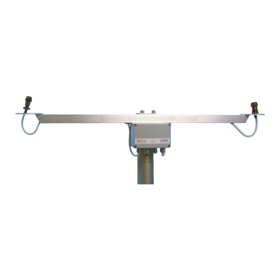
Flange for mounting Vaisala wind vane WAT12 consists of a printed circuit board unit in a junction box and a cross arm for mounting the wind sensors. A 4-wire cable for the wind speed and direction signals and power supply is needed between the transmitter and the receiving end. -
Page 10: Esd Protection
Any modification voids your warranty. 2.2.1 ESD protection Electrostatic Discharge (ESD) can damage electronic circuits. Vaisala products are adequately protected against ESD for their intended use. However, it is possible to damage the product by delivering electrostatic discharges when touching, removing, or inserting any objects in the equipment housing. -
Page 11: Installation
Additional protection is needed in regions with frequent, severe thunderstorms, especially when long line cables (>30 m (98 ft)) are used. Vaisala recommends using a surge protector, such as WSP150, in all sites with an elevated risk of a lightning strike. -
Page 12: Figure Recommended Mast Location In Open Area
WAT12 User Guide M210309EN-B Figure 1 Recommended mast location in open area Any object of height (h) does not remarkably disturb wind measurement at a minimum distance of 10 × h. There must be at least 150 m (500 ft) open area in all directions from the mast. -
Page 13: Installing Wat12
1.5 × W. 3.2 Installing WAT12 1. To remove WAT12 cover, remove the 4 screws holding the cover. 2. Select the current output span and direction and speed scaling. For examples on selecting scales and ranges, see the figures in... -
Page 14: Jumper Settings
M210309EN-B 7. Attach the unit on the top of a pole mast with the mounting clamp as shown in Mounting WAT12 on top of pole mast (page 23). 8. Mount the sensors onto the cross arm. Mounting wind sensor to WAT12 (page 25) and Vaisala Anemometer WAA151 User Guide and Vaisala Wind Vane WAV151 User Guide. -
Page 15: Figure 4 Jumpers For Setting 4
Chapter 3 – Installation For example, you can set the wind speed output 1 ... 5 mA which corresponds to speed values 0 ... 51.2 m/s and to direction values 0 ... 540 degrees. This range does not change the scaling of 360 degrees corresponding to one full turn, rather it allows to calculate the average direction during northerly winds. -
Page 16: Connections
Figure 6 Jumpers for setting 0 ... 10 mA, 0° ... 540°, 0 ... 51.2 m/s 3.4 Connections WAT12 provides the line cable entry through a gland for a cable with a diameter 7 ... 10 mm. For better protection against RF interference, bend the cable shield. -
Page 17: Figure 7 Cable Shield Bent Over Plastic Sleeve And O-Ring
Chapter 3 – Installation Figure 7 Cable shield bent over plastic sleeve and o-ring WAT12 has 3 I/O connectors X1: For the anemometer cable X2: For the power and signal cable X3: For the wind vane cable Table 4 I/O connectors Connector Description Plug-in connector with screw terminals (5 pcs) for the anemometer cable. -
Page 18: Sensor Wiring
The signal and sensor power outputs are also current limited. Typically, only a 4-wire shielded cable is required for the line between WAT12 and the receiving end. Two of the 4 wires provide the operating power for the system. The other 2 are for the current source outputs from the WAT12 transmitter;... -
Page 19: Figure 9 Typical System With 24 V Dc Power Supply And 5 Ma
Chapter 3 – Installation Figure 9 Typical system with 24 V DC power supply and 5 mA signal currents The following figure shows wiring for high-noise environment. Make sure that you also ground the cable at the power supply. Figure 10 Wiring for high-noise environment The following figure shows wiring for long distance with the 5 mA loop current. -
Page 20: Powering
Figure 12 Long distance wiring with 4 wires 3.4.3 Powering WAT12 accepts a wide range of input power 12 ... 28 V DC. When the 5 mA loop current is selected, the total current consumption is less than 40 mA including the sensors and the loop current. -
Page 21: Optional Heating Power
Chapter 3 – Installation 3.4.4 Optional heating power WAT12 also provides the sensors with a throughput for optional heating power. The heating power connection requires an extra pair of wires. Since the heating elements in the shafts of WAA151 and WAV151 typically consume some 500 mA, the heating power is most conveniently supplied from a local power source. -
Page 22: Figure 14 Basic Wiring With Waa151 And Wav151 Sensors
Twisted pairs (GL) F VIO 4-20mA Wind direction Wind speed 4-20mA Power supply +12...28 VDC SHIELD HTNG HTNG SHIELD **) current scale is jumper selectable in WAT12 Vin- Vin- Vin+ Vin+ WAA151 F BLK Spare HTNG HTNG E BLU Fout SHIELD Figure 14 Basic wiring with WAA151 and WAV151 sensors... -
Page 23: Figure 15 Wiring With Whp151 Mains Power Supply
Chapter 3 – Installation Figure 15 Wiring with WHP151 mains power supply... -
Page 24: Figure 16 Wiring With Whp25 Mains Power Supply And Wa25 Sensors
WAT12 User Guide M210309EN-B Figure 16 Wiring with WHP25 mains power supply and WA25 sensors... -
Page 25: Mounting Thermostat Switch
3.6 Mounting WAT12 on top of pole mast The following figure shows mounting WAT12 on the top of a Ø 60 mm pole mast, with the standard mounting clamp. The arrow on the cover of the junction box must point to north. -
Page 26: Figure 19 Mounting Wat12 On Top Of Pole Mast
WAT12 User Guide M210309EN-B Figure 19 Mounting WAT12 on top of pole mast WARNING! A long cable between different units (sensors, transmitters, power supplies, and displays) can cause a lethal surge voltage, if a lightning strikes in the vicinity. Always ground the mast equipment case close to the... -
Page 27: Mounting Wind Sensor To Wat12
Figure 20 Installing WAA151 and WAV151 to WAT12 WAA151 cup assembly WAV151 tail assembly Cross arm WAT12 Connector Mounting flange South North 3.8 Alignment After mounting WAT12 to the mast, make sure that the WAV151 end of the cross arm is pointing to north. -
Page 28: Verification
WAT12 User Guide M210309EN-B 3.9 Verification If the signal cable from WAT12 is connected to the data collection system and the system is powered up, make sure that the wind readings react correctly. • To test the anemometer, rotate the cups manually. -
Page 29: Maintenance
Speed 0.0 m/s, 0.8 m/s, 51.2 m/s 1. To remove WAT12 cover, remove the 4 screws holding the cover. 2. To enable the test stage, remove the jumper J5 from the jumper block X4. 3. Select one of the direction and speed alternatives with jumpers J1, J2, J3, and J4. -
Page 30: Replacing Consumables
When replacing the component board, pay attention to ESD protection. When you replace the thermostat switch, see Mounting thermostat switch (page 23). Table 8 Spare parts Spare part Order code Component Board for WAT12 16637WA Thermostat switch 16923WA Mains power supply WHP151 Mains power supply... -
Page 31: Troubleshooting
Chapter 5 – Troubleshooting 5. Troubleshooting 5.1 Troubleshooting WAT12 Table 9 Common problems and their remedies Problem Probable cause Remedy Data is not received by the data Improper or loose connections. Check wiring and tighten the collecting system. screw terminals. Shaft heating of the sensors is Improper or loose connections. -
Page 32: Technical Data
WAT12 User Guide M210309EN-B 6. Technical data 6.1 WAT12 specifications Table 10 Operating environment Property Description/Value Operating temperature –55 ... +55 °C (-67 ... +131 °F) Storage temperature –60 ... +70 °C (-76 ... +158 °F) Operating humidity 0 ... 100 %RH Table 11 Inputs and outputs... -
Page 33: Figure 21 Dimensions In Mm (Inches)
Chapter 6 – Technical data Property Description/Value Full-scale options (jumper selectable) For direction: 0 ... 360° / 0 ... 540° For speed: 0 ... 51.2 m/s (0 ... 115 mph) / 0 ... 76.8 m/s (0 ... 172 mph) Signal cable Min. -
Page 35: Warranty
Please see the applicable supply contract or Conditions of Sale for details of the warranty for each product. Technical support Contact Vaisala technical support at helpdesk@vaisala.com. Provide at least the following supporting information as applicable: • Product name, model, and serial number •... - Page 38 www. v aisala.com...
Need help?
Do you have a question about the WAT12 and is the answer not in the manual?
Questions and answers