Table of Contents
Advertisement
Quick Links
INSTALLATION MANUAL
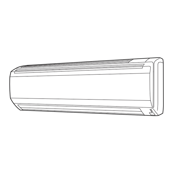
VRF system indoor unit (Wall mounted type)
For authorized service personnel only.
MANUEL D'INSTALLATION
Appareil intérieur à système VRF (Type montage mural)
Pour le personnel agréé uniquement.
MANUAL DE INSTALACIÓN
ASUB18TLAV2
ASUB24TLAV2
Unidad interior del sistema VRF (Tipo montado en pared)
Únicamente para personal de servicio autorizado.
PART No. 9373370512-01
Advertisement
Table of Contents

Subscribe to Our Youtube Channel
Related Manuals for Fujitsu Airstage ASUB18TLAV2


Summary of Contents for Fujitsu Airstage ASUB18TLAV2
- Page 1 INSTALLATION MANUAL VRF system indoor unit (Wall mounted type) For authorized service personnel only. MANUEL D’INSTALLATION Appareil intérieur à système VRF (Type montage mural) Pour le personnel agréé uniquement. MANUAL DE INSTALACIÓN ASUB18TLAV2 ASUB24TLAV2 Unidad interior del sistema VRF (Tipo montado en pared) Únicamente para personal de servicio autorizado.
-
Page 2: Table Of Contents
INSTALLATION MANUAL 1.2. SPECIAL PRECAUTIONS PART No. 9373370512-01 VRF system indoor unit (Wall mounted type) When Wiring Contents ELECTRICAL SHOCK CAN CAUSE SEVERE PERSONAL INJURY OR DEATH. ONLY A QUALIFIED, EXPERIENCED ELECTRICIAN SHOULD ATTEMPT TO WIRE THIS SYSTEM. • Do not supply power to the unit until all wiring and tubing are completed or reconnected SAFETY PRECAUTIONS ................... -
Page 3: About This Product
2. ABOUT THIS PRODUCT Name and shape Q’ty Application Air cleaning For installation, refer to the filter “CLEANING AND CARE” in 2.1. Precautions for using R410A refrigerant the operation manual WARNING Air cleaning filter holder Do not introduce any substance other than the prescribed refrigerant into the refrigera- tion cycle. -
Page 4: Installation Work
3. INSTALLATION WORK 3.3. Installing the unit Correct initial installation location is important because it is difficult to move unit after it is WARNING installed. Install the air conditioner in a location which can withstand a load of at least 5 times the 3.1. -
Page 5: Pipe Installation
Drain hose Wall hook bracket Drain cap Insert the drain cap until it butts against the drain port. Insert the drain hose until it butts Tapping screw (big) against the drain port. 3.3.2. Cutting the hole in the wall for the connecting piping 3.3.4. -
Page 6: Pipe Requirement
4.3.3. Pipe connection 4.2. Pipe requirement CAUTION CAUTION Be sure to install the pipe against the port on the indoor unit and the outdoor unit cor- rectly. If the centering is improper, the flare nut cannot tightened smoothly. If the flare Refer to the installation manual for the outdoor unit for description of allowable pipe nut is forced to turn, the threads will be damaged. -
Page 7: Access To The Control Box
[For (D) Left bottom piping, (E) Left piping and (F) Center piping, (G) Left rear 6. ACCESS TO THE CONTROL BOX piping] • Preset the end of the pipe. To access the control box with “7. ELECTRICAL WIRING” or “8. FIELD SETTING”, •... -
Page 8: Electrical Wiring
A. Current breaker requirements 7. ELECTRICAL WIRING • MCA: Minimum Circuit Ampacity MAX. CKT. BKR Model • MAX. CKT. BKR : Maximum Circuit (Fuse capacity) WARNING Breaker ASUB18TLAV2 0.53 A Electrical work must be performed in accordance with this Manual by a person certified 15 A under the national or regional regulations. -
Page 9: Unit Wiring
7.3.2. Transmission cable 7.3. Unit wiring 1-3/16 in (30 mm) • Before attaching the cable to terminal block. 7.3.1. Power supply cable Conduit connector Shielded cable 1-3/8 in (35 mm) 6-7/8 in (175 mm) (no film) • When the 2 cables are attached. GOOD PROHIBITED Earth... -
Page 10: Wiring
7.4. Wiring 7.5. Optional parts wiring Connect the end of the connection cable fully into the terminal block. 7.5.1. Layout of the indoor unit PCB Controller PCB Power indicator CN65 CN820 lamp (green) CNA04 DIP switch (SET 2) CNA02 CNB01 CNA01 CNA03 (The grommet edging is not used.) -
Page 11: External Input And External Output (Optional Parts)
When connected to Dry contact terminals of multiple indoor units with a connected unit, 7.6. External input and external output (Optional parts) insulate each indoor unit with relay, etc. as shown on below example. 7.6.1. External input P.C.B • Indoor unit can be Operation/Stop, Emergency stop or Forced stop by using indoor unit PCB CNA01 or CNA02. -
Page 12: Field Setting
● Forced thermostat off function 8.1. Setting the address [“Edge” input only] 8.1.1. Manual address setting method Function Connector Input signal Command • The indoor unit address and the refrigerant circuit address can also be set up through setting the wireless remote controller OFF →... -
Page 13: Custom Code Setting
Adjust the cool air trigger tempera- 00 Standard 8.2. Custom code setting Cool air ture. To lower the trigger tempera- 01 Adjust (1) temperature ture, use setting 01. To raise the Selecting the custom code prevents the indoor unit mix-up. trigger 02 Adjust (2) trigger temperature, use setting 02. - Page 14 Temperature conditions when the external heater is ON/OFF Function Function Setting number Default Details number Temperature (t) = Room temperature - set temperature 00 Setting 0 Set value of function: 61 01 Setting 1 01 to 09 02 Setting 2 03 Setting 3 04 Setting 4 t <...
-
Page 15: Finishing
• Refrigerant address example Check that: (Example) ADDRESS : 30 When connected from the (G) left rear, the drain hose is at the bottom left of the wall 1 cycle 12 sec pipe. OPERATION indicator (View from indoor) 1.0s 1.0s 1.0s 1.0s 1.0s... -
Page 16: Test Run
10. TEST RUN 12. ERROR CODES If you use a wired type remote controller, error codes will appear on the remote controller 10.1. Test run using Outdoor unit (PCB) display. If you use a wireless remote controller, the lamp on the photodetector unit will output error codes by way of blinking patterns.
Need help?
Do you have a question about the Airstage ASUB18TLAV2 and is the answer not in the manual?
Questions and answers