Table of Contents
Advertisement
Quick Links
Owner's Manual & Safety Instructions
Save This Manual
operating, inspection, maintenance and cleaning procedures. Write the product's serial number in the
back of the manual near the assembly diagram (or month and year of purchase if product has no number).
Keep this manual and the receipt in a safe and dry place for future reference.
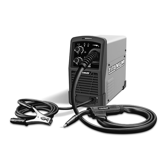
EASY-FLUX125
56355
Email our technical support at: productsupport@harborfreight.com
When unpacking, make sure that the product is intact
and undamaged. If any parts are missing or broken,
please call 1-888-380-0318 as soon as possible.
©
Copyright
2019 by Harbor Freight Tools
No portion of this manual or any artwork contained herein may be reproduced in
any shape or form without the express written consent of Harbor Freight Tools.
Diagrams within this manual may not be drawn proportionally. Due to continuing
improvements, actual product may differ slightly from the product described herein.
Tools required for assembly and service may not be included.
Keep this manual for the safety warnings and precautions, assembly,
Visit our website at: http://www.harborfreight.com
®
. All rights reserved.
Read this material before using this product.
Failure to do so can result in serious injury.
SAVE THIS MANUAL.
19l
Advertisement
Table of Contents

Related Manuals for Titanium EASY-FLUX125


Summary of Contents for Titanium EASY-FLUX125
- Page 1 (or month and year of purchase if product has no number). Keep this manual and the receipt in a safe and dry place for future reference. EASY-FLUX125 56355 Visit our website at: http://www.harborfreight.com Email our technical support at: productsupport@harborfreight.com...
-
Page 2: Table Of Contents
table of contents Safety ............2 Welding Tips ..........20 Specifications ..........7 Maintenance ..........24 Setup ............8 Parts List and Diagram ......27 Basic Welding ..........12 Warranty ............ 28 WaRning SyMBOlS and dEFinitiOnS This is the safety alert symbol. It is used to alert you to potential personal injury hazards. - Page 3 Fume and gas Safety INHALATION HAZARD: Welding and plasma cutting produce toxic fumes. 1. Exposure to welding or cutting exhaust 3. Keep head out of fumes. fumes can increase the risk of developing Do not breathe exhaust fumes. certain cancers, such as cancer of the 4.
-
Page 4: Electrical Safety
Electrical Safety ElEctRic SHOcK can Kill. 1. turn off, disconnect power, and 6. do not expose welders to rain or wet conditions. discharge electrode to ground before setting Water entering a welder will increase down torch/electrode holder and before service. the risk of electric shock. -
Page 5: Maintenance
Welder use and care 1. do not use the welder if the switch does not turn 4. Store idle welders out of the reach of it on and off. Any welder that cannot be controlled children and do not allow persons unfamiliar with the switch is dangerous and must be repaired. -
Page 6: Extension Cords
grounding tO pREVEnt ElEctRic SHOcK and dEatH FROM incORREct gROunding WiRE cOnnEctiOn: check with a qualified electrician if you are in doubt as to whether the outlet is properly grounded. do not use the Welder if the power cord or plug is damaged. if damaged, have it repaired by a service facility before use. -
Page 7: Specifications
Symbology Wire Feed (Speed) Inches Per Minute American Wire Gauge Workpiece Ground Cable Electric Shock Hazard. Torch Cable Do not touch energized parts. Overheat Shutdown Indicator Inhalation Hazard. Keep head out of fumes and use proper ventilation. Cooling Fan Read manual before Housing Ground Point setup and/or use. -
Page 8: Setup
Setup Read the EntiRE iMpORtant SaFEty inFORMatiOn section at the beginning of this manual including all text under subheadings therein before set up or use of this product. tO pREVEnt SERiOuS inJuRy FROM accidEntal OpERatiOn: turn the power Switch off and unplug the Welder before setup. note: Remove the protective foam and cardboard from the Welder before setup. - Page 9 Feed tensioner idler arm 6. Turn the Feed Tensioner knob counterclockwise to loosen it enough to pull it down to remove tension. The spring-loaded Idler Arm will move up as shown. Feed Roller 7. Feed Roller instructions: Knob Check that the Feed Roller is turned to properly match the wire size marked on the Wire Spool: a.
- Page 10 iMpORtant Securely hold onto the end of the welding wire and keep tension on it during the following steps. if this is not done, the welding wire will unravel and unspool which can cause tangling and feeding problems. HOld WiRE Feed Wire Wire...
- Page 11 15. Point the Gun away from all objects. Flux gun Press and hold the Cold Feed Switch until the wire feeds through the end of the Gun two inches. the wire liner may come out with the welding wire. this is normal, just turn off the Welder and push the wire liner back into the gun.
-
Page 12: Basic Welding
Basic Welding Read the EntiRE iMpORtant SaFEty inFORMatiOn section at the beginning of this manual including all text under subheadings therein before welding. tO pREVEnt SERiOuS inJuRy: protective gear must be worn when using the Welder; minimum shade number 10 full face shield (or welding mask), ear protection, welding gloves, sleeves and apron, NIOSH-approved respirator, and fire resistant work clothes without pockets should be worn when welding. -
Page 13: Front Panel Controls
Front panel controls alarm indicator power indicator Voltage Knob Flux gun Wire Speed Knob ground clamp Item 56355 For technical questions, please call 1-888-380-0318. Page 13... -
Page 14: Weld Settings
interior controls idler arm Feed tensioner Wire Spool Spool Knob Wire inlet Feed cold Feed liner Roller Knob Switch Weld Settings Refer to the Settings Chart on the inside of the Welder door for Flux-Cored and MIG Weld settings. The chart is only intended to show general guidelines for different wire sizes and for different thicknesses of material. -
Page 15: Duty Cycle (Duration Of Use)
Duty Cycle (Duration of Use) avoid damage to the Welder by not welding For example, a welder with a 40% duty cycle at 90 A for more than the prescribed duty cycle time. welding current must be allowed to rest for at least The Duty Cycle defines the number of minutes, within a 6 minutes after every 4 minutes of continuous welding. -
Page 16: Setting Up The Weld
Setting up the Weld 1. Make practice welds on pieces of scrap the same thickness as your intended workpiece to practice technique before welding anything of value. Clean the weld surfaces thoroughly with a wire brush or angle grinder; there must be no rust, paint, oil, or other materials clamps on the weld surfaces, only bare metal. - Page 17 5. Turn the Power Switch off and do not touch the Gun’s Trigger and before connecting power Power Cord: Plug the Power Cord into a Switch properly grounded, GFCI protected 120 V AC (20 amp rated) receptacle that matches the plug and turn the Power Switch ON.
-
Page 18: Basic Welding Technique
Basic Welding technique 1. Press (and hold) Trigger and contact the area to be welded with electrode wire to ignite arc. stringer bead weave bead 2. For a narrow weld, you can usually draw the wire in a steady straight line. This is called a stringer bead. - Page 19 note: If Welder is used too long, the Overload Indicator lights up and the unit automatically shuts down. The Welder automatically returns to service after cooling off. Should this occur, rest the Flux Gun on an electrically non- Flux gun Overload conductive, heat-proof surface, such as a indicator...
-
Page 20: Welding Tips
Welding tips A typical flux-cored wire (FCAW) weld before cleaning. A good way to test welding technique is to examine a weld bead weld’s appearance after it has cooled and the slag slag spatter has been removed. Then, better welding can be learned by adjusting your weld technique to remedy any problems found. - Page 21 Weld diagnosis Workpiece Heat control / Weld penetration EXcESS pEnEtRatiOn OR inadEQuatE pEnEtRatiOn pROpER pEnEtRatiOn BuRn-tHROugH not hot enough ideal heat too hot How to increase workpiece heat How to reduce workpiece heat and increase penetration: and limit penetration: (to weld tHicKER workpieces properly) (to weld tHinnER workpieces properly) a.
- Page 22 Weld problems Penetration (Workpiece Heat Control) EXcESS pEnEtRatiOn OR pROpER pEnEtRatiOn inadEQuatE pEnEtRatiOn BuRn-tHROugH Weld is visible underneath and Weld does not penetrate the Weld droops on top and bulges slightly on top. joint fully, just on the surface. underneath, or falls through entirely, making a hole.
- Page 23 porosity Excessive Spatter Small cavities or holes in the bead. Fine spatter is normal. Spatter that is grainy and large is a problem. VIEW VIEW pOSSiBlE cauSES and SOlutiOnS pOSSiBlE cauSES and SOlutiOnS 1. dirty workpiece or welding wire: Clean workpiece down to bare metal. 1.
-
Page 24: Maintenance
Maintenance tO pREVEnt SERiOuS inJuRy, FiRE and BuRnS: unplug the Welder, rest the Flux gun on a heat-proof, electrically non-conductive surface, and allow all parts of the Welder to cool thoroughly before service. 1. BEFORE EacH uSE, inspect the general 2. -
Page 25: Troubleshooting
troubleshooting iMpORtant! Be cERtain to shut off the Welder, disconnect it from power, and discharge the Flux gun to ground before adjusting, cleaning, or repairing the unit. problem possible causes likely Solutions 1. Insufficient wire feed tension. 1. Increase wire feed tension properly. Follow step 16 on page 11. - Page 26 Troubleshooting (continued) iMpORtant! Be cERtain to shut off the Welder, disconnect it from power, and discharge the Flux gun to ground before adjusting, cleaning, or repairing the unit. problem possible causes likely Solutions 1. Tripped thermal protection device. 1. If the Alarm Indicator is illuminated without an error code, Welder has overheated and shut down.
-
Page 27: Parts List And Diagram
parts list and diagram part description part description Strap Front Housing Door Latch Ground Cable Door Flux Gun Wire Feed Mechanism Knob Spool Knob Front Panel Middle Panel Front PCB Power Switch Torch Cable Support Cable Grommet Left Panel Power Cord Output Transformer Main Control Board Cold Feed Switch... -
Page 28: Please Read The Following Carefully
plEaSE REad tHE FOllOWing caREFully THE MANUFACTURER AND/OR DISTRIBUTOR HAS PROVIDED THE PARTS LIST AND ASSEMBLY DIAGRAM IN THIS MANUAL AS A REFERENCE TOOL ONLY. NEITHER THE MANUFACTURER OR DISTRIBUTOR MAKES ANY REPRESENTATION OR WARRANTY OF ANY KIND TO THE BUYER THAT HE OR SHE IS QUALIFIED TO MAKE ANY REPAIRS TO THE PRODUCT, OR THAT HE OR SHE IS QUALIFIED TO REPLACE ANY PARTS OF THE PRODUCT.
Need help?
Do you have a question about the EASY-FLUX125 and is the answer not in the manual?
Questions and answers
How to replace the liner in the welder the flux core liner from titanium