Table of Contents
Advertisement
Quick Links
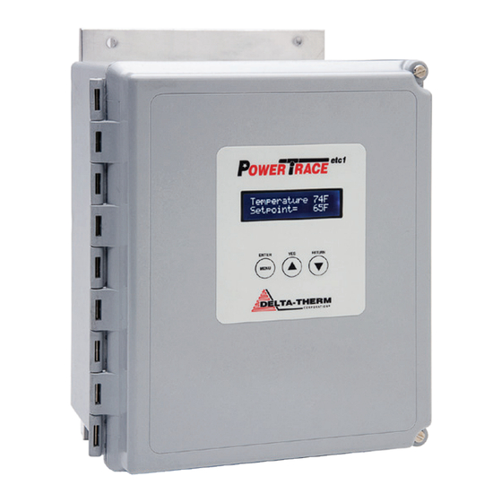
PowerTrace etc1
DELTA-THERM Corporation, 6711 Sands Rd Suite A, Crystal Lake, IL 60014
Contents
seCtIon 1.
Overview
1.1 Precautions ........................................................................................ 2
1.2 Base model components ................................................................... 2
1.3 Operation ........................................................................................... 2
1.4 Default Settings ................................................................................. 2
seCtIon 2. iNSTALLiNG
2.1 installing the PowerTrace control panel ............................................ 3
2.2 installing the 100-Ohm platinum rTD ............................................... 4
2.3 electrical connections ....................................................................... 5
2.4 wiring contacts for remote alarm ...................................................... 6
seCtIon 3. PrOGrAMMiNG
3.1 LeD display settings ......................................................................... 7
3.2 Programming setpoint temps and alarms ......................................... 8
3.3 Ground fault alarm ...........................................................................11
3.4 LeD screen alarm displays and resetting alarms .............................11
3.4 Locking the keypad ..........................................................................11
seCtIon 4. TeSTiNG AND TrOuBLe ShOOTiNG
3.1 Maintenance ....................................................................................12
3.2 System function test ........................................................................12
3.3 Trouble shooting and Technical Support ..........................................12
www.Delta-Therm.com
Installation Instructions
PowerTrace etc1 Control
(847) 526-2407 Fax (847) 526-4456
1
page
(800) 526-7887
Advertisement
Table of Contents

Related Manuals for Delta-Therm PowerTrace etc1

Summary of Contents for Delta-Therm PowerTrace etc1
-
Page 1: Table Of Contents
4. TeSTiNG AND TrOuBLe ShOOTiNG 3.1 Maintenance ..................12 3.2 System function test ................12 3.3 Trouble shooting and Technical Support ..........12 www.Delta-Therm.com DELTA-THERM Corporation, 6711 Sands Rd Suite A, Crystal Lake, IL 60014 (800) 526-7887 (847) 526-2407 Fax (847) 526-4456... -
Page 2: Section 1. Overview
The uL Listing is for hazardous locations C1D2 Groups A, B, C, & D. The eTC-277 model is uL pending as of this printing. The PowerTrace etc1 is intended to control heat trace cable in the application of pipe trac- 1.3 oPeRAtIon ing or tank tracing. -
Page 3: Section 2. Installation
Section 2. Installation 2.1 InstALLIng the The PowerTrace etc1 control panel can be installed outdoors or indoors. Locate per PoweRtRACe etC1 building plans or other suitable location as directed. Mount the PowerTrace control panel ContRoL PAneL to unistrut type brackets using the external mounting holes on the enclosure to allow air circulation around all surfaces for cooling. -
Page 4: Installing The 100-Ohm Platinum Rtd
Detail 3. Attach rTD sensor to pipe and route the rTD sensor wire to the terminal block inside of the PowerTrace control panel. DELTA-THERM Corporation, 6711 Sands Rd Suite A, Crystal Lake, IL 60014 (800) 526-7887 (847) 526-2407 Fax (847) 526-4456... -
Page 5: Electrical Connections
LOAD 1 LINE/NEU LOAD 2/NEU Detail 5. wire heat trace cable and power feed to junction box, then to PowerTrace control panel. DELTA-THERM Corporation, 6711 Sands Rd Suite A, Crystal Lake, IL 60014 (800) 526-7887 (847) 526-2407 Fax (847) 526-4456... -
Page 6: Wiring Contacts For Remote Alarm
FITTING REQUIRES A 1-1/8" DIAMETER HOLE. ALARM CONTACTS NEUTRAL 24 VAC TO 120VAC LINE 120V 0.5A MAX Detail 6. wire alarm contacts. DELTA-THERM Corporation, 6711 Sands Rd Suite A, Crystal Lake, IL 60014 (800) 526-7887 (847) 526-2407 Fax (847) 526-4456... -
Page 7: Led Display Settings
Section 3. Programming 3.1 LeD DIsPLAy settIngs The banner heading “Delta-Therm Corp heat Trace CTL” is displayed after applying power to the control panel. After the banner heading is displayed the LeD screen will display the temperature as detected by the rTD and the control panel setpoint temperature. -
Page 8: Programming Setpoint Temps And Alarms
Detail 10. Press the “YeS/up” arrow button to raise setpoint temperature. Press the “reTurN/down” arrow button to lower setpoint temperature. Press eNTer/MeNu button to move on to next parameter. DELTA-THERM Corporation, 6711 Sands Rd Suite A, Crystal Lake, IL 60014 (800) 526-7887 (847) 526-2407 Fax (847) 526-4456... - Page 9 Detail 12. Press the “YeS/up” arrow button to raise the high Temp Alarm Setpoint. Press the “reTurN/down” arrow button to lower The high Temp Alarm Setpoint. Press eNTer/MeNu button to move on to next parameter. DELTA-THERM Corporation, 6711 Sands Rd Suite A, Crystal Lake, IL 60014 (800) 526-7887 (847) 526-2407 Fax (847) 526-4456...
- Page 10 Detail 14. To return to main display press the “reTurN/down” arrow button. Current mon. off ENTER RETURN Detail 15. when current monitoring is disabled this message will be displayed. DELTA-THERM Corporation, 6711 Sands Rd Suite A, Crystal Lake, IL 60014 (800) 526-7887 (847) 526-2407 Fax (847) 526-4456...
-
Page 11: Ground Fault Alarm
Move the dipswitch into the left position to enable the keypad. Move the dipswitch into in the right position to disable the keypad. DELTA-THERM Corporation, 6711 Sands Rd Suite A, Crystal Lake, IL 60014 (800) 526-7887 (847) 526-2407 Fax (847) 526-4456... -
Page 12: Maintenance
4. Activate by setting setpoint above the temperature at the rTD, verify readings. 5. return setpoint to required value. 4.3 tRoUBLe-shootIng 1. verify that the heat trace cable and PowerTrace etc1 are the same voltage. AnD teChnICAL sUPPoRt 2. 0°F or 1023°F temperature is displayed: check rTD & rTD wiring.
Need help?
Do you have a question about the PowerTrace etc1 and is the answer not in the manual?
Questions and answers