Table of Contents
Advertisement
Quick Links
Advertisement
Table of Contents

Related Manuals for Ezurio Sona NX611


Summary of Contents for Ezurio Sona NX611
- Page 1 User / Integration Guide Sona™ NX611 Modules v0.3...
-
Page 2: Revision History
11 June 2024 Ezurio branding. Sue White Dave Drogowski Updated Renderings with current labels and updated regulatory 06 August 2024 Brian Petted Brian Petted statements. Pete Scharpf https://www.ezurio.com/ Americas: +1-800-492-2320 © Copyright 2024 Ezurio Europe: +44-1628-858-940 All Rights Reserved Hong Kong: +852-2762-4823... -
Page 3: Table Of Contents
FCC and ISED Modular Certification Requirements ..................................17 Federal Communication Commission Interference Statement ............................. 17 Innovation, Science and Economic Development, Canada (ISED) Statement ........................19 Sona NX611 SIP Certified Module Host Board Requirements ................................21 SONA™ NX611 M.2 2230 Module Mounting Guidelines .................................. 23 Regulatory ................................................ 24 https://www.ezurio.com/... -
Page 4: Introduction
SONA™ NX611 M.2 2230 Module Note: Data in this document is drawn from several sources and is subject to change. Figure 1: Sona NX611 SIP Module Figure 2: Sona NX611 M.2 1216 SMT Module Figure 3: Sona NX611 M.2 2230 Module https://www.ezurio.com/ Americas: +1-800-492-2320 ©... -
Page 5: Sona™ Nx611 Sip Module
User /Integration Guide 2 SONA™ NX611 SIP Module This section describes the hardware footprint, mechanical drawing and hardware pinout of the Sona NX611 SIP module. It provides details and pin assignments critical to hardware integration of the module. SONA™ NX611 SIP Module PCB Footprint Module dimensions of the Sona NX611 SIP wireless module are 11 x 11 x 1.69 mm. -
Page 6: Sona™ Nx611 Sip Module Mechanical Drawing
The last digit of Wi-Fi MAC address is assigned to either 0, 2, 4, 6, 8, A, C, E. The Bluetooth MAC address is the Wi-Fi MAC address plus 1. https://www.ezurio.com/ Americas: +1-800-492-2320 © Copyright 2024 Ezurio Europe: +44-1628-858-940 All Rights Reserved Hong Kong: +852-2762-4823... -
Page 7: Sona™ Nx611 Sip Module Pinout
Sona NX611 User /Integration Guide SONA™ NX611 SIP Module Pinout Table 1: Sona NX611 SIP Module Pinout Pin Name Description Number Ground VIO_SD SDIO Power Supply Ground SD_CMD SD Command/response (input/output) SD_CLK SD Clock input SD_DAT[1] SD Data line bit[1]... - Page 8 GPIO[27] GPIO[29]/JTAG_TMS JTAG controller select (input) GPIO[31]/JTAG_TDO JTAG test data signal (output) GPIO[28]/JTAG_TCK JTAG test clock signal (input) GPIO[30]/JTAG_TDI JTAG test data signal (input) Ground https://www.ezurio.com/ Americas: +1-800-492-2320 © Copyright 2024 Ezurio Europe: +44-1628-858-940 All Rights Reserved Hong Kong: +852-2762-4823...
-
Page 9: Sona™ Nx611 1216 Module
User /Integration Guide 3 SONA™ NX611 1216 Module This section describes the hardware footprint, mechanical drawing and hardware pinout of the Sona NX611 M.2 1216 module. It provides details and pin assignments critical to hardware integration of the module. SONA™ NX611 M.2 1216 Module PCB Footprint Module dimensions of the Sona NX611 M.2 1216 wireless module are 12 x 16 x 1.72 mm. -
Page 10: Sona™ Nx611 M.2 1216 Module Mechanical Drawing
The last digit of Wi-Fi MAC address is assigned to either 0, 2, 4, 6, 8, A, C, E. The Bluetooth MAC address is the Wi-Fi MAC address plus 1. https://www.ezurio.com/ Americas: +1-800-492-2320 © Copyright 2024 Ezurio Europe: +44-1628-858-940 All Rights Reserved Hong Kong: +852-2762-4823... -
Page 11: Sona™ Nx611 M.2 1216 Module Pinout
Sona NX611 User /Integration Guide SONA™ NX611 M.2 1216 Module Pinout Table 2: Sona NX611 M.2 1216 Module Pinout PCIe M.2 Name Pin Name NX611 Description Number UIM_POWER_SRC/GPIO1 UNUSED UIM_POWER_SNK UNUSED UIM_SWP UNUSED 3.3V 3.3V 3.3V 3.3V Ground Ground RESERVED... - Page 12 PCM_CLK/I2S_SCK Ground Ground W_DISABLE2# IND_RST_BT LED_2# UNUSED LED_1# UNUSED RESERVED/VIO_1.8 VIO_1.8 RESERVED UNUSED Ground Ground USB_D- UNUSED USB_D+ UNUSED Ground Ground 3.3V 3.3V 3.3V 3.3V https://www.ezurio.com/ Americas: +1-800-492-2320 © Copyright 2024 Ezurio Europe: +44-1628-858-940 All Rights Reserved Hong Kong: +852-2762-4823...
- Page 13 (Shared WiFi and Bluetooth, single trace Pad variant) Ground Ground Ground Ground Ground Ground Ground Ground Ground Ground WL_C1 UNUSED Ground Ground Ground Ground Ground Ground Ground Ground Ground Ground https://www.ezurio.com/ Americas: +1-800-492-2320 © Copyright 2024 Ezurio Europe: +44-1628-858-940 All Rights Reserved Hong Kong: +852-2762-4823...
-
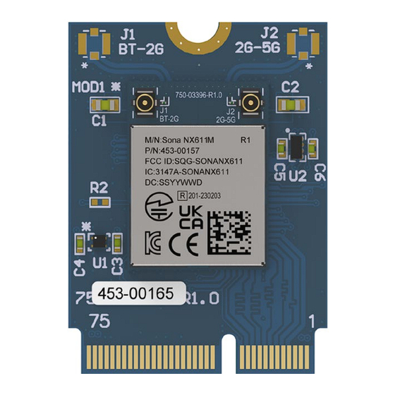
Page 14: Sona™ Nx611 M.2 2230 Module
The last digit of Wi-Fi MAC address is assigned to either 0, 2, 4, 6, 8, A, C, E. The Bluetooth MAC address is the Wi-Fi MAC address plus 1. https://www.ezurio.com/ Americas: +1-800-492-2320 © Copyright 2024 Ezurio Europe: +44-1628-858-940 All Rights Reserved Hong Kong: +852-2762-4823... -
Page 15: Sona™ Nx611 M.2 2230 Module Pinout
Sona NX611 User /Integration Guide SONA™ NX611 M.2 2230 Module Pinout Table 3: Sona NX611 M.2 2230 Module Pinout Pin # PCIe M.2 Name Pin Name NX611 3.3 V 3.3 V USB_D+ USB_D+ 3.3 V 3.3 V USB_D- USB_D- LED_1# (I)(OD) LED_1# (I)(OD) PCM_CLK/I2S_SCK (I/O)(0/1.8V) - Page 16 RESERVED/VIO 1.8V RESERVED RESERVED UIM_SWP/PERST1# UIM_SWP/PERST1# RESERVED RESERVED UIM_POWER_SNK/CLKREQ1# UIM_POWER_SNK/CLKREQ1# UIM_POWER_SRC/ UIM_POWER_SRC/ GPIO_1/PEWAKE1# GPIO_1/PEWAKE1# RESERVED RESERVED 3.3 V 3.3 V RESERVED RESERVED 3.3 V 3.3 V https://www.ezurio.com/ Americas: +1-800-492-2320 © Copyright 2024 Ezurio Europe: +44-1628-858-940 All Rights Reserved Hong Kong: +852-2762-4823...
-
Page 17: Fcc And Ised Modular Certification Requirements
Ezurio provides a FCC Modular Certified reference design. It is a controlled impedance PCB that uses microstrip trace design to route RF signals from the module to the coaxial connectors. Please use the latest CAD files from the Ezurio web site when incorporating the Sona™ module into a new design. CAD files are provided in native Altium as well as Gerber and PDF formats. - Page 18 Contains FCC ID: SQG-SONANX611 Information on Test Modes and Additional Testing Requirements Test tool: The NXP LabTool shall be used to set the module to transmit continuously. Please contact Ezurio for further information and usage conditions. Additional Testing, Part 15 Subpart B Disclaimer The module is only FCC authorized for the specific rule parts listed on the grant, and that the host product manufacturer is responsible for compliance toany other FCC rules that apply to the host not covered by the modular transmitter grant of certification.
-
Page 19: Innovation, Science And Economic Development, Canada (Ised) Statement
émetteur), l'autorisation du Canada n'est plus considéré comme valide et l'ID IC ne peut pas être utilisé sur le produit final. Dans ces circonstances, l'intégrateur OEM sera chargé de réévaluer le produit final (y compris l'émetteur) et l'obtention d'une autorisation distincte au Canada. https://www.ezurio.com/ Americas: +1-800-492-2320 © Copyright 2024 Ezurio Europe: +44-1628-858-940 All Rights Reserved Hong Kong: +852-2762-4823... - Page 20 Le manuel de l'utilisateur final doit inclure toutes les informations réglementaires requises et avertissements comme indiqué dans ce manuel. https://www.ezurio.com/ Americas: +1-800-492-2320 © Copyright 2024 Ezurio Europe: +44-1628-858-940 All Rights Reserved Hong Kong: +852-2762-4823...
-
Page 21: Sona Nx611 Sip Certified Module Host Board Requirements
Module, Sona NX611 SIP, 1 RF Trace Pin The reference design for the Ezurio Sona NX611 SIP Module has been integrated into the Sona NX611 Development Board. It is 6-layer PCB with a total thickness of 0.79mm. The reference design includes designs for the singe port version as well as the dual port version. - Page 22 Table 6: RF Critical Components BOM L4, L9 0.6nH Murata LQP03TN0N6B02D J6, J7 I-PEX 20449-001E Taoglas 20449.001E-01 * RF Critical Components That Cannot be Substituted https://www.ezurio.com/ Americas: +1-800-492-2320 © Copyright 2024 Ezurio Europe: +44-1628-858-940 All Rights Reserved Hong Kong: +852-2762-4823...
-
Page 23: Sona™ Nx611 M.2 2230 Module Mounting Guidelines
1.8 mm, 2.3 mm and 3.2 mm connector heights and the JAE (https://www.jae.com/en/) SM3 series provides 1.2 mm, 2.15 mm, 3.1 mm and 4.1 mm connector heights. Because the Sona NX611 M.2 module is a single-side component module, we recommend the following part numbers which have 2.3 mm and 3.1 mm connector height: Figure 12: Sona NX611 M.2 2230 Stand-off and Connector... -
Page 24: Regulatory
Table 8: SONA™NX61X countries with certification (M.2 1216 Module and M.2 2230 Module) Country/Region Regulatory ID USA (FCC) SQG-SONANX611M Canada (ISED) 3147A-SONANX611M Japan (MIC) Australia New Zealand https://www.ezurio.com/ Americas: +1-800-492-2320 © Copyright 2024 Ezurio Europe: +44-1628-858-940 All Rights Reserved Hong Kong: +852-2762-4823...
Need help?
Do you have a question about the Sona NX611 and is the answer not in the manual?
Questions and answers