
Related Manuals for Hotjet ZETXe


Summary of Contents for Hotjet ZETXe
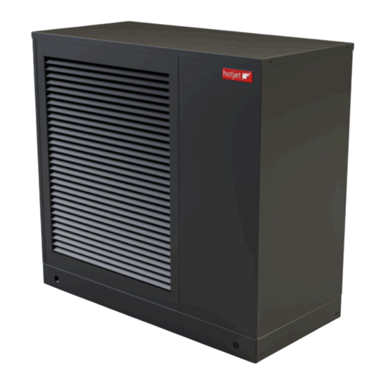
- Page 1 INSTALLATION INSTRUCTIONS FOR HOTJET ZETXe HEAT PUMP Monobloc heat pumps Air/water system for heating and cooling 7ZETXe 10ZETXe 15ZTEXe Please read this manual carefully before putting this equipment into operation/use!
-
Page 2: Table Of Contents
10.4 View and spare parts......................................22 10.5 Declaration of conformity.....................................24 10.6 Hydraulic integration......................................30 10.7 Annex 1: Electrical diagram of 7 ZETXe................................31 10.8 Annex 2: Electrical diagram of 10 ZETXe................................33 10.9 Annex 3: Electrical diagram of 15 ZETXe................................35 2/36... -
Page 3: Safety Instructions
DANGER: Do not place the heat pump in areas that may be flooded with water. Thank you for purchasing the Hotjet heat pump. To ensure it DANGER: The equipment should not be installed near the occurrence of flammable liquids and serves you well for as long as possible, familiarize yourself with the manual. -
Page 4: Warranty, Post-Warranty Conditions And Liability For Defects
Warranty, post-warranty conditions and liability for defects For a complaint to be recognized, it is necessary for the customer to inform the supplier - HOTJET CZ s.r.o. - in cooperation with the seller in a timely manner. Warranty conditions are specified in the document "Terms and Conditions of Sale and Delivery." Although the device's integrity has been verified several times during the manufacturing process, malfunctions can still occur. -
Page 5: Storage
- If you disconnect the heat pump from the heating system or ATTENTION: When handling the pump with the electrical power supply, it must be stored at temperatures pallet removed, use the openings in the base of the above 0°C to protect it from freezing residual water in the heat pump. -
Page 6: Technical Parameters
NOTE: The ZETXe heat pump is primarily designed for household use. NOTE: For air-to-water heat pumps, it is important to ensure a minimum heating water temperature of 18°C for the defrosting mode. -
Page 7: Technical Data Zetxe
Technical data ZETXe Technical specification of HOTJET ZETXe Model 7 ZETXe 10 ZETXe 15 ZETXe Performance data Heating capacity [kW] / Power input [kW] / Heating factorr [COP] Nominal performance (min. / max.) 6,0 (0,9-8,0) 8,0 (2,0-10,7) 10,0 (3,0-14,5) Nominal performance / COP pro A7/W35 1) - pro 60Hz... - Page 8 Width x depth x height 1 271 x 600 x 1 136 Weight of outdoor unit Electrical data Compressor power supply V/ Ph/ Hz 230/1~/50 400/3~/50 400/3~/50 Switchboard power supply with RVS V/ Ph/ Hz 230/1~/50 230/1~/50 230/1~/50 Power supply for electric bivalence V/ Ph/ Hz 400/3~/50 400/3~/50...
-
Page 9: Dimension Drawing
5.1 Dimension drawing Position Description Dimension Heating water output from Ø 28 mm the heat pump Heating water input to the Ø 28 mm heat pump Cable grommet max. Ø 34 mm Condensate drain ex G1” Nuts for anchoring or silentblocks 15ZETXe 70 mm... -
Page 10: Temperature Operating Range Zetxe
Volumetric flow rate of number temperature [C°] of heating water [C°] heating water [ �� A-23 Minimal A-23 Maximal Maximal Maximal Maximal Minimal The ZETXe heat pump is fully capable of operating at temperatures throughout the entire operating range. 10/36... -
Page 11: Installation Instructions
This section of the documentation is intended for qualified installation and service technicians as a guide for proper installation, operation, and maintenance of the HOTJET heat pump. It is important to study it carefully, as failure to follow the instructions provided may result in heat pump malfunction, material damage, burns, or electrical shock. -
Page 12: Placement On The Roof
- The heat pump must be accessible from all sides. INSTALLATION WITH CONDENSATE DRAINAGE Legenda TV output TV input Cable harness Flexible hose UV resistant insulation Protector Concrete base Piping Sifon Sewer pipe Silent blocks/building feet Pic. 11 ZETXe mounted on a concrete base using a siphon. 12/36... -
Page 13: Safe Distances From Light Wellsí
Gravel Sewer pipe DN100 Silent blocks/building feet Pic. 12 ZETXe mounted on a concrete base with the use of each. NOTE: This sketch serves as a rough guide. 6.10 Safe distances from light wellsí - To ensure compliance with the safety concept of the equipment, the following minimum distance from light shafts applies. -
Page 14: Assembly
Assembly 7.2 Connectors WARNING: Foreign objects such as rust, sand, or DANGER: Connector damage is possible. sealing material can negatively impact the operational safety of the heat pump. It is important - Tighten the connector's screw closure by hand to ensure that the heat pump is not exposed to these risks. only, without using any tools. -
Page 15: Creating A Plug Connection
7.5 Connection to the heating system 7.3 Creating a plug connection - Thread and secure hydraulic couplings onto the heating connections, following the procedure outlined in Chapter 7.3 - Stretch the O-ring of the pipe until it reaches the specified "Creating a Socket Connection"... -
Page 16: Protection Against Frost
7.6 Protection against frost 7.7 Rules for outdoor sensor placement - Once the heat pump is fully installed and powered, its - The coldest wall of the house is typically oriented to the control monitors the temperatures in the condenser. If the north. -
Page 17: Water Treatment Without Chemicals
ATTENTION: Heat pump systems components from Hotjet CZ s.r.o. require filling Depending on the materials used, it is essential to fill the and operation with deionized water (completely heating system with demineralized soft water or fully desalinated). We also recommend using a deionized water. -
Page 18: Cable Connection
ATTENTION: Cable laying instructions considering possible malfunctions of the heating system. - Thoroughly check the correct connection of all cables and connectors. - Route wiring from busbars separately from cables with voltages exceeding 50 V to prevent electromagnetic interference with the controller. - Ensure that electrical cables are not hot to the touch. -
Page 19: Commissioning
compressor activation (it automatically shuts off after a few seconds) and the fan. Also, check the values of all Commissioning temperature sensors in this menu. WARNING: Before starting the heat pump, - To reset the lowered outdoor temperature, use the disconnect the power supply to the heating "Consumption Diagnostics"... -
Page 20: Maintenance
Perform the following routine checks and cleaning tasks 10. Maintenance regularly: Lift and remove the rear grille of the heat pump. Remove leaves and other debris from the As part of regular maintenance, a comprehensive system ventilation grille and fins of the evaporator. status check should be conducted to ensure safety and Check the condensate drainage function and maintain energy supplies. -
Page 21: Switch Settings
10.3 Switch settings ATTENTION:Everything is already set from the factory, if any problem arises, please contact a service technician. WARNING: Risk of electric shock. WARNING: Ensure that the heat pump is disconnected from the power supply to prevent possible electric shock. When replacing the slide switch, it is essential to ensure that all electrical power is disconnected and the equipment is turned off. -
Page 22: View And Spare Parts
10.4 View and spare parts Pic. 25 Heat pump parts part.2 Position Description Frequency converter Evaporator temperature sensor Evaporator Chokes Air temperature sensor Terminal block Pic. 24 Heat pump parts part 1. SEC board 22/36... - Page 23 Obr. 26 Díly chladícího boxu Position Description Position Description Capacitor High pressure sensor Expansion valve High Pressure Pressure Pressure Switch Low pressure sensor Low pressure temperature sensor Filter High pressure temperature sensor Separator Heating water outlet temperature sensor 4-way valve Heating water inlet temperature sensor Compressor Subcooling temperature sensor...
-
Page 24: Declaration Of Conformity
10.5 Declaration of conformity 24/36... - Page 25 25/36...
- Page 26 26/36...
- Page 27 27/36...
- Page 28 28/36...
- Page 29 29/36...
-
Page 30: Hydraulic Integration
10.6 Hydraulic integration Basic diagram of a heat pump connection to a direct heating circuit.Typical wiring diagram - does not replace the installation project. Legend control parts B - Temperature sensor K25/K26 - Water flow immersion heater Q3 - Three-way diverting valve Q9 - Circulating pump Legend used parts BO - Boiler... -
Page 31: Annex 1: Electrical Diagram Of 7 Zetxe
10.7 Annex 1: Electrical diagram of 7 ZETXe 31/36... - Page 32 32/36...
-
Page 33: Annex 2: Electrical Diagram Of 10 Zetxe
10.8 Annex 2: Electrical diagram of 10 ZETXe 33/36... - Page 34 34/36...
-
Page 35: Annex 3: Electrical Diagram Of 15 Zetxe
10.9 Annex 3: Electrical diagram of 15 ZETXe 35/36... - Page 36 36/36...
Need help?
Do you have a question about the ZETXe and is the answer not in the manual?
Questions and answers