Advertisement
9005013COM (Taupe and White)
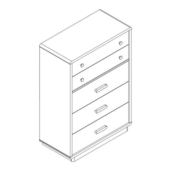
Cosmo Living Valencia Tall Dresser
Date of Purchase: ____/____/_____
Lot Number:
THIS INSTRUCTION BOOKLET CONTAINS IMPORTANT SAFETY INFORMATION. PLEASE READ AND KEEP FOR FUTURE REFERENCE.
Do Not Return This Product!
Call: 1-800-489-3351 (toll free)
Visit: www.ameriwoodhome.com
WARNING
–
–Anchor unit to stud in wall (if instructed to)
–Do not allow children climb on unit
–
Contact Us!
Helpful Hints
B349005XXXCOM00SW
Easy
Follow Ameriwood Home
042024SW
Tough
Advertisement
Table of Contents

Related Manuals for Ameriwood HOME Cosmo Living Valencia 9005013COM


Summary of Contents for Ameriwood HOME Cosmo Living Valencia 9005013COM
- Page 1 THIS INSTRUCTION BOOKLET CONTAINS IMPORTANT SAFETY INFORMATION. PLEASE READ AND KEEP FOR FUTURE REFERENCE. Do Not Return This Product! Call: 1-800-489-3351 (toll free) Visit: www.ameriwoodhome.com Easy Tough WARNING Follow Ameriwood Home – –Anchor unit to stud in wall (if instructed to) –Do not allow children climb on unit –...
-
Page 2: Helpful Hints
Contact Us! Contact Us! Do NOT return this product! Call us! Visit ameriwoodhome.com 1-800-489-3351 Helpful Hints PEOPLE NEEDED FOR ASSEMBLY: 2 - Compression Wood Dowels are tapped in with a hammer. - Make sure to always face the point between (+) & (-) on top of the Cam Locks towards the outer edge. -
Page 3: Before You Start
Before You Start Read through each step carefully and follow the proper order. Separate and count all your parts and hardware. Give yourself enough room for the assembly process. Have the following tools: Phillips Head Screwdriver and Hammer. ... - Page 4 Before You Start Please Note: You may need to lightly tap the wood dowels with a hammer into the holes during your assembly process. Insert wood dowel completely into the hole. Not Actual Size Wood Dowel Actual Size Wood Dowel will extend out approximately 3/8”.
-
Page 5: Board Identification
Board Identification Not actual size TOP PANEL LEFT SIDE PANEL RIGHT SIDE PANEL FRONT MOLDING COUNTERWEIGHT BOTTOM PANEL BACK PANEL FRONT STRETCHER BACK STRETCHER... - Page 6 Board Identification Not actual size SIDE STRETCHER LEFT SIDE STRETCHER RIGHT UPPER DRAWER FACE UPPER SIDE DRAWER (LEFT) UPPER SIDE DRAWER (RIGHT) UPPER BACK DRAWER BOTTOM DRAWER FACE BOTTOM SIDE DRAWER (LEFT) BOTTOM SIDE DRAWER (RIGHT)
- Page 7 Board Identification Not actual size BOTTOM BACK DRAWER DRAWER BOTTOM DRAWER SUPPORT For any replacement part, see page 9.
- Page 8 Board Identification Not actual size...
-
Page 9: Part Number Reference
Part Number Reference Each part has a unique part number. Please refer to the appropriate part number when Before throwing any packaging, please verify all contents and make sure you have received all the part listed above. 9005013COM LABEL PART NAME (Taupe and White) TOP PANEL T9005013010SW... -
Page 10: Part List
Part List Actual Size For any replacement hardware, see page 12. TSW0002 TSW0004 TSW0007 TSW0001 Cam Lock DOWEL SCREW Cam Bolt 15-10 M8 X 30 CBS 3.5 x 14 TSW3006 TSW0008 TSW0015 HANDLE SCREW SCREW NAIL CBS 4 x 38... - Page 11 Part List Not Actual Size x5 SETS TSW3003 TSW3004 TSW1003 HANDLE ROUND KNOB DRAWER SLIDE 300 MM x1 SET TSW2004 ANTI TIPPING KIT...
- Page 12 Hardware Number Reference Each part has a unique part number. Please refer to the appropriate part number when contacting customer service for replacement parts. Before throwing any packaging, please verify all contents and make sure you have received all the part listed above. 9005013COM MODEL# (Taupe and White)
-
Page 13: Finished Edge
Step 1 Insert Cam Bolts (A) x 4 to Top Panel (1). Attach Anti Tipping Kit (K) to Top Panel (1) and use (Kc) to tighten. “Note : this (Kc) will be tighten in step 29”. FINISHED EDGE... - Page 14 Step 2 Insert Cam Bolts (A) x 3, Cam Locks (B) x 4 and Wood Dowels (C) x 4 to Left Side Panel (2). Insert Cam Bolts (A) x 3, Cam Locks (B) x 4 and Wood Dowels (C) x 4 to Right Side Panel (3).
- Page 15 Step 3 x5 SETS Attach Drawer Slides (J) CR x 5 to Right Side Attach Drawer Slides (J) CL x 5 to Left Side Panel (3), secure with Screws (D) x 15 as illustrated. Panel (2), secure with Screws (D) x 15 as illustrated. Use these holes : Use these holes : Slide CL , Screw position on Panel (2)
- Page 16 Step 4 Insert Cam Locks (B) x 2 and Wood Dowels (C) x 2 to Panel (5). Insert Cam Locks (B) x 2 and Wood Dowels (C) x 2 to Panel (4).
- Page 17 Step 5 Insert Cam Bolts (A) x 2 and Wood Dowels (C) x 2 to Panel (8). Insert Cam Bolt (A) x 1 and Cam Lock (B) x 1 to Panel (10) and Panel (11). Insert Cam Locks (B) x 2 to Panel (9).
- Page 18 Step 6 Attach Panel (10) and Panel (11) to Panel (9), tighten the Cam Locks clockwise. Important!, Ensure the small holes facing up!
- Page 19 Step 7 Attach Panel (8) to Panel (10) and Panel (11), tighten the Cam Locks clockwise. Dowel facing up...
- Page 20 Step 8 Attach Panel (8), panel (9), panel (10) and panel (11) to Bottom Panel (6), secure with Screw (E) x 10 as illustrated. FINISHED EDGE Curve facing up...
- Page 21 Step 9 Turn over the Panel (6), insert Cam Bolts (A) x 4. Pro Tip : Second person is recomended for ease of assembly on this step...
- Page 22 Step 10 Attach Panel (5) x 2 and Panel (4) to Left Side Panel (2), tighten the Cam Locks clockwise. FINISHED EDGE FINISHED EDGE Pro Tip : Second person is recomended for ease of assembly on this step...
- Page 23 Step 11 Attach Right Side Panel (3) to Panel (4) and Panel (5), tighten the Cam Locks clockwise. FINISHED EDGE FINISHED EDGE Pro Tip : Second person is recomended for ease of assembly on this step...
- Page 24 Step 12 Attach Bottom Panel (6) to Left Side Panel (2) and Right Side Panel (3), tighten the Cam Locks clockwise. FINISHED EDGE FINISHED EDGE FINISHED EDGE Pro Tip : Second person is recomended for ease of assembly on this step...
- Page 25 Step 13 Attach Top Panel (1) to Left Side Panel (2) and Right Side Panel (3), tighten the Cam Locks clockwise. FINISHED EDGE FINISHED EDGE FINISHED EDGE Pro Tip : Second person is recomended for ease of assembly on this step...
- Page 26 Step 14 IMPORTANT ! THE BACK PANEL IS A STRUCTURAL PART OF THIS UNIT AND MUST BE INSTALLED PROPERLY. With the assistance of second person, carefully turn the unit upside down. Attach Back Panel (7) with Nails (F) x 20. Ensure the unit is rectangle. Distance from corner to corner must be equal. UNFINISHED EDGE Pro Tip : Second person is recomended for ease of assembly on this step...
- Page 27 Step 15 Insert Cam Bolts (A) x 25 to Panel (12) x 2 and Panel (16) x 3.
- Page 28 Step 16 Insert Cam Locks (B) x 25 to Panel (13) x 2, Panel (14) x 2, Panel (17) x 3, Panel (18) x 3 and Panel (21) x 5.
- Page 29 Step 17 Attach Panel (13) and Panel (14) to the Panel (12), tighten the Cam Locks clockwise.
- Page 30 Step 18 Attach Panel (21) to the Panel (12), tighten the Cam Locks clockwise.
- Page 31 Step 19 Insert Drawer Bottom (20) through the grooves of Panel (13) and (14) then slot into groove of Panel (12) as illustrated.
- Page 32 Step 20 Line up the groove of Panel (15) with Panel (20), secure with screws (E) x 5 as illustrated.
- Page 33 Step 21 x2 SETS Attach Drawer Slide (J) DL to Panel (13), secure with Screws (D) x 3 as illustrated. Attach Drawer slide (J) DR to Panel (14), secure with Screws (D) x 3 as illustrated. Use these holes : Use these holes : (DR) (DL)
- Page 34 Step 22 Attach Knobs (I) x 2 onto Panel (12), secure with Screws (G) x 2 as illustrated.
- Page 35 Step 23 Attach Panel (17) and Panel (18) to the Panel (16), tighten the Cam Locks clockwise.
- Page 36 Step 24 Attach Panel (21) to the Panel (16), tighten the Cam Locks clockwise.
- Page 37 Step 25 Insert Drawer Bottom (20) through the grooves of Panel (17) and (18) then slot into groove of Panel (16) as illustrated.
- Page 38 Step 26 Line up the groove of Panel (19) with Panel (20), secure with Screws (E) x 5 as illustrated.
- Page 39 Step 27 x3 SETS Attach Drawer Slide (J) DL to Panel (17), secure with Screws (D) x 3 as illustrated. Attach Drawer Slide (J) DR to Panel (18), secure with Screws (D) x 3 as illustrated. Use these holes : (DR) Use these holes : (DL)
- Page 40 Step 28 Attach Handle (H) onto Panel (16), secure with Screws (G) x 2 as illustrated.
- Page 41 Step 29 For Masonry, Concrete, or other wall materials: Consult your local hardware store for appropriate anchors to securely IMPORTANT: THIS UNIT MUST BE SECURE TO THE WALL TO HELP PREVENT TIPOVER. FOLLOW THESE INSTRUCTIONS TO INSTALL THE ANTI-TIPPING SAFETY BRACKET PROVIDED WITH THIS PRODUCT.
- Page 42 Step 30 Carefully insert Drawers into the unit as illustrated.
- Page 43 Maximum Loads This unit has been designed to support the maximum loads shown. Exceeding these load limits could cause sagging, instability, product collapse, and/or serious injury. 50 lbs 23 kg 25 lbs. 11 kg each drawer 27 lbs. 12 kg each drawer Warning: Risk of serious injury to person - do not place a television on this furniture.
- Page 44 We would like to extend a big “Thank You” to all to assemble this our customers for taking the of our customers for taking the time to assemble Seeds product, and to give us your valuable this Ameriwood Home product, and to give us your feedback. valuable feedback...
- Page 45 Español Cubierta Delantera futuro. No Regrese este producto! Comuniquese con nuestro amistoso equipo de servicio al cliente para obtener ayuda. Llamenos al: 1-800-489- Visitar: www.ameriwoodhome.com PRECAUCION Este mueble puede volcarse y causar graves heridas y/o muerte. Anclar el mueble a un poste de madera en la pared (si esto se requiere). No Permita que los niños monten el mueble.
- Page 46 Español Página 11 Paso 3 - Inserte el Bolt(1) x4, el Lock(2) x8, el Dowel(3) x12 en el panel lateral(B) y (C) y el panel de moldeo(E) x2. Inserte el Página 12 Paso 4 - Inserte Cam Lock(2) x12 en el panel de contrapeso(N) y el soporte de la caja(L) x4. Página 13 Página 14 Paso 6 - Añadir el panel de contrapeso(N) al panel lateral izquierdo(B), apriete el bloqueo de la cámara.
- Page 47 Español ADVERTENCIA Lesiones por aplastamiento graves o fatales puede ocurrir desde la punta del mueble. Para evitar volcar: * Instale la restricción de vuelco provista en los cajones más bajos acomodar, no instale televisores u otros objetos pesados en la parte superior de este producto * Nunca permita que los niños trepen o cuelguen de los cajones, puertas o estanterías * Nunca abra más de un cajón a la vez El uso de restricciones sobre volteos solo puede reducir, pero no eliminar, el riesgo...
- Page 48 Français capot avant ultérieure. Ne pas retourner ce produit! Contactez notre équipe de service à la clientèle amical pour aider. Appel: 1-800-489-3351 (gratuit) Visite: www.ameriwoodhome.com MISE EN GARDE Ce mobilier peut basculer et causer des blessures graves et / ou la mort. Ancrer les meubles à...
- Page 49 Français Page 11 Étape 3 - Insérez le Bolt(1) x4, le Lock(2) x8, le Dowel(3) x12 dans le panneau latéral(B) et (C) et le panel de moulage(E) x2. Page 12 Étape 4 - Insérez Cam Lock(2) x12 dans le panneau de contrepoids(N) et le support de la boîte(L) x4. Page 13 Page 14 Étape 6 - Ajoutez le panneau de contrepoids(N) au panel latéral gauche(B), serrez le verrou de l’appareil photo.
- Page 50 Français Avert ssement Des lésions graves ou fatales par écrasement peuvent survenir à part r de la pointe du meuble. Pour éviter de se retourner : * Placez les objets les plus lourds dans les boîtes inférieures L’ut lisat on de restrict ons sur les virages ne peut que réduire, mais pas éliminer, le risque de virage OPTION 1: mur.
Need help?
Do you have a question about the Cosmo Living Valencia 9005013COM and is the answer not in the manual?
Questions and answers