
Related Manuals for Hussmann OCU-CR200VF5

Summary of Contents for Hussmann OCU-CR200VF5
- Page 1 ADIABATIC COOLING SOLUTION OUTDOOR REFRIGERATION UNIT INSTALLATION MANUAL OCU-CR200VF5 / OCU-CR200VF5SL JAN 2021 - AJHH9A2000130A...
-
Page 2: Table Of Contents
CONTENTS GENERAL INFORMATION SPRINKLING CONTROL AND TEMPERATURE SETTINGS Symbols Stop Think Act 5.1 Controller Settings 1.3 Staff Training 1.4 Electrical Connections 1.5 Refrigerants 1.6 Rated Specification DECOMMISSIONING & DISPOSAL PRE-INSTALLATION 6.1 Decommisioning 6.2 Disposal 2.1 Name of Each part 2.2 Operating Environment 2.3 Handling and Transporting Cases 2.4 Shipping Damages and Shortages TROUBLESHOOTING 2.5 Rating Plates 7.1 Troubleshooting... -
Page 3: General Information
Personal Protective Equipment whilst leakage, electric shock or fire may installing the case. occur. Always keep manual in safe place. NO WALK: Do not walk on top or on any parts of the unit. Unit damages or personal injuries may occur. NO SIT: Do not sit on top or on any parts of the unit. Unit damages or personal injuries may occur. PAGE 3 2HP OUTDOOR REFRIGERATION UNIT - HUSSMANN... - Page 4 NO CONNECTING SOCKETS: Do not use any connecting socket or extension cords. Be sure to use private line or socket as the main power source. Failure to do so could result in electric shock or fire. PAGE 4 2HP OUTDOOR REFRIGERATION UNIT - HUSSMANN...
-
Page 5: Stop Think Act
Incomplete attachment may lead to penetration of out the training and requirements needed for their water, thereby causing current leak and fire/electrical maintenance technician staff to be educated to use the shock. unit correctly. The unit should always be kept in good - Confirm that solenoid valve cover is securely installed working order to ensure installer and user safety. Injury to personnel and damage to the unit and its components may occur if instructions in the manual are not correctly followed. If information would like to be added to this manual, or if suggestions would like to me made, contact Hussmann directly at any time. PAGE 5 2HP OUTDOOR REFRIGERATION UNIT - HUSSMANN... -
Page 6: Refrigerants
Pay close attention during transport, installation and dismantling not to damage the refrigerant pipelines. CAUTION: Gas is under high pressure. EVENT OF DAMAGE: Keep surrounding flames or sources of ignition away from the appliance. Properly ventilate the premises and use a breathing apparatus. Turn the unit off and notify the customer service department. Fire and heat may cause gas receptacles to rupture. Use water spray/ not jet or fog to extinguish. RATED SPECIFICATION PAGE 6 2HP OUTDOOR REFRIGERATION UNIT - HUSSMANN... -
Page 7: Pre-Installation
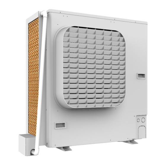
PRE INSTALLATION Name of Each Part Front of the Adiabatic Solution Top Bracket End Cap Corner Bracket Evaporative Cooling Pad Panasonic 2hp Unit Manual Ball Valve (Control Water Flow) Drain Outlet Drain Bracket Back of the Adiabatic Solution Elbow 90º Water Pipe Side Panel Solenoid Valve Box PAGE 7 2HP OUTDOOR REFRIGERATION UNIT - HUSSMANN... -
Page 8: Operating Environment
Warehouse Managers may refuse loading. packing etc confirm with the parts list, attached Transportation requirements are to ensure unit to the unit for any short supplied and or damaged integrity and prevent unnecessary damage and avoid parts etc. If required notify Hussmann or delays in the unit installation schedule. representative within seven (7) days of delivery. Before storing the unit, ensure packaging is unbroken and does not display defect that may compromise preservation of the unit. -
Page 9: Rating Plates
PPE, first aid, disposal and emergency management. Refer page 29 (Risk Analysis) For MSDS sheet contact your Hussmann CAUTION: Care must be taken to avoid damage to solenoid valve box and electrical cable mounted under or at the left hand side of the unit INSPECT UNDERSIDE BEFORE LIFTING WITH FORKLIFT. -
Page 10: Installation
Bottom panel Next, assemble the structure of adiabatic cooling solution using screws to fix the inner corner bracket to the bottom panel. Mount the left side panel. Use the existing holes and screws on the unit to fix the panel and Right side panel avoid drilling. Left side panel Bottom panel NOTE: Information in this manual is to be followed in conjunction with specifications, work practices and regulations of the customer, installing company and relevant industry. PAGE 10 2HP OUTDOOR REFRIGERATION UNIT- HUSSMANN... - Page 11 Insert the cooling pad holder bracket into the socket, faucet socket and rubber seal. Ensure drain brain brackets that the two holes are aligned, the drain bracket corners are sealed and the PVC socket is tightened to avoid leakage. Use thread seal tape where necessary. RH drain bracket LH drain bracket 3.5B PVC faucet socket PVC valve socket Rubber Seal Insert the cooling pads onto the drain. Noted 3.5C that as you insert the cooling pads, they will be sitting on top of the PVC sitting which prevents them from touching the drain bottom. Place the joint drain brackets on to the bottom panel. PAGE 11 2HP OUTDOOR REFRIGERATION UNIT- HUSSMANN...
- Page 12 WARNING: Before Gluing the pipes ensure that pipe holes are facing downwards, and it is tightened to avoid leakage. PVC Pressure Pipe Length: 310mm Diameter: 25mm Top Panel PVC Pressure End Cap Diameter: 25mm PVC Pressure Pipe Length: 780mm Diameter: 25mm PVC Pressure Elbow Diameter: 25mm 3.10 Place the connected pipes on the right-side panel and inner corner bracket flange as show. 3.12 Fix the corner bracket and screw it from the top. The corner bracket bottom flange should hold the bottom panel. PAGE 12 2HP OUTDOOR REFRIGERATION UNIT- HUSSMANN...
- Page 13 WARNING: This step may require help to be completed. Use these existing holes 3.15 Screw the top panel to the left side panel FIG. A Use these existing holes FIG. B PAGE 13 2HP OUTDOOR REFRIGERATION UNIT- HUSSMANN...
- Page 14 (Flow Controller) 20mm PVC Pipe 3.17 Place the joined water pipes on the installed Diameter; 20mm brackets slot from the top. Length: 50mm 3.19 Insert the universal bush into the valve box bracket and fix the to the valve and fittings to the valve bracket using cable ties. Ensure that the elbow angle is appropriate and use PVC glue to fix the piping as marked. Use PVC Glue Use PVC Glue Valve box bracket PAGE 14 2HP OUTDOOR REFRIGERATION UNIT- HUSSMANN...
- Page 15 INSTALLATION 3.20 Connect the water pipe / hose into the water inlet as marked Water Inlet Manual Ball Valve (control water flow) PAGE 15 2HP OUTDOOR REFRIGERATION UNIT- HUSSMANN...
- Page 16 Manual valve handle removed Rotate by 90° to open the solenoid valve manually. c. Open the manual ball valve turn it by 10° or less to avoid water overflow. d. Monitor the water flow to be sufficient across the cooling pads and ensure that there is no leakage from the pipe fittings and the drain. WARNING: During this test, if the water flow is high or more than it is needed, use the manual ball valve to control the water flow and set it for the actual automatic operation. e. After checking for leakage and the optimal water flow, set the solenoid valve state back to automatic. Set it at upward position for automatic control. PAGE 16 2HP OUTDOOR REFRIGERATION UNIT- HUSSMANN...
-
Page 17: Wiring And Circuit Diagram
STEP C. With the unit open. Feed this cable up Feed a single phase 10A power plug cable through the wire access holes as indicated. to the unit through the lower right hand side access panel and attached with a cable gland. Power cable to go through here WARNING:- To avoid serious injury from electrical shock, always Wiring Access disconnect the electrical power at Lower Panel Hole the main when replacing or fitting any electrical component. PAGE 17 2HP OUTDOOR REFRIGERATION UNIT- HUSSMANN... - Page 18 STEP A. Connect a new 3 x 0.75mm2 shielded cable for 240V solenoid valve. Connect the active brown wire to the terminal block (L). Solenoid active Connect the neutral blue wire to the wire terminal block (10). Connect the Green/yellow earth wire to the Second neutral wire Earth screw. from terminal Neutral block 9 to terminal block N Power active Power neutral wire wire Earth Active PAGE 18 2HP OUTDOOR REFRIGERATION UNIT- HUSSMANN...
- Page 19 STEP E. Attached a cable gland to the unit and place the 3 core cable into a conduit. Run the cable/conduit out of the unit and towards the solenoid valve as pictured. STEP H. Unscrew the housing cover and unscrew the side cap. Run Cable/ Conduit Attached a cable toward the solenoid valve gland Unscrew housing cover Unscrew side cap PAGE 19 2HP OUTDOOR REFRIGERATION UNIT- HUSSMANN...
- Page 20 Insert the coil back to the solenoid valve Housing cover and tighten the nut. Screw nut Seal Washer Side cap 3 core shielded cable STEP K. Connect the 3 core shielded cable to active brown wire (label 1) Connect the neutral blue wire to (label 2) Connect the earth wire Green/yellow wire to STEP N. Mount the valve box onto the valve box (label Earth). bracket and use screws to fix it. Earth Active (Label 1) Neutral (Label 2) PAGE 20 2HP OUTDOOR REFRIGERATION UNIT- HUSSMANN...
- Page 21 (3) Electric wire should not touch high temperature components (compressor, gas cooler, discharge piping, etc.) and any metal edge. Attached cable clip Note:- Rechecking electrical termination for tightness. During wiring the solenoid valve. It is a requirement to check the electrical connection for tightness and re-tension where needed prior to powering up the equipment. PAGE 21 2HP OUTDOOR REFRIGERATION UNIT- HUSSMANN...
-
Page 22: Wiring Diagram
WIRING AND CIRUIT DIAGRAM 3.23 Adiabatic cooling solution with Solenoid valve wiring diagram PAGE 22 2HP OUTDOOR REFRIGERATION UNIT- HUSSMANN... -
Page 23: Maintenance And Inspection
Check supply power is ready and correct voltage. • Check evaporative cooling pads are secure in place. (by Licensed Person) • Visually check the 2HP refrigeration unit for any • Confirm correct operation of RCD (if fitted) (by damage and take appropriate remedial action (Call Licensed Person) a licence technician or call Hussmann) • Ensure that the solenoid valve is installed the right way up (refer to 3.22 section) • Check that all pvc pipe are installed correctly CAUTION: If any damaged electrical components are identified during inspection isolate case power and contact service contractor. -
Page 24: Cleaning And Maintenance
5. Visual check solenoid valve for wear and tear or broken. If broken (Call a licence electrician to replaced soleniod valve) 6. Ensure all cable connections, including screw terminals, earth leads and straps, are secure. 7. Ensure that the correct fuse rating and type is fitted for all circuits. 8. Ensure that there are no refrigerant leaks. 9. Check that all case panels, pvc pipe and extrusions are secure and undamaged. 10. Check for rust or paint damage. 11. Safely switch power to the unit back on. With case power turned on: 12. Check that solenoid valve and controls are working correctly. PAGE 24 2HP OUTDOOR REFRIGERATION UNIT- HUSSMANN... -
Page 25: Evaporating Cooling Pad
MAINTENANCE AND INSPECTION EVAPORATIVE COOLING PAD REPLACEMENT 4.52 Remove the top bracket. Unscrew the removable corner bracket from the top. 4.51 Unscrew and top panel from both sides of the adiabatic cooling solution. 4.53 Remove the old evaporative cooling pads Unscrew Unscrew PAGE 25 2HP OUTDOOR REFRIGERATION UNIT- HUSSMANN... - Page 26 MAINTENANCE AND INSPECTION EVAPORATIVE COOLING PAD REPLACEMENT 4.56 Screw back the top panel to the side panels. 4.54 Place the new evaporative cooling pads. Insert screws Insert screws 4.57 Place and screw back the removable corner racket. 4.55 Install back the top panel. PAGE 26 2HP OUTDOOR REFRIGERATION UNIT- HUSSMANN...
-
Page 27: Sprinkling Control And Temperature Settings
SPRINKLING CONTROL & TEMPERATURE SETTINGS CONTROLLER SETTINGS Setting method of sprinkling control for 2HP CO2 condensing unit Target model: OCU-CR200VF5 OCU-CR200VF5SL Change the liquid tube electromagnetic valve output to the sprinkling electromagnetic valve output 1. Turn ON No.8 of 8P DIP switch (SW13). 2. Set the rotary switch (SW11) to “ALM HISTORY” 7seg LED display: “OFF” (initial setting) 3. Operate the ▲/▼ switch and change the setting to ON. 7seg LED display: “ON” 4. Set the rotary switch back to “OPERATION”. 5. Turn OFF No.8 of 8P DIP switch (SW13). The liquid tube electromagnetic valve output operates as the sprinkling electromagnetic valve output. Set the ambient temperature which start sprinkling control. -
Page 28: Decommissioning And Disposal
Removal of the refrigeration unit is to be in the • Sheet Metal and other various metals. reverse order of installation listed previously. • Copper / Aliminum • Cardboard • Dismantle the in accordance refrigeration unit • with the local laws on waste disposal and in respect of the environment in which we live. Remaining by commercial waste management PAGE 28 2HP OUTDOOR REFRIGERATION UNIT- HUSSMANN... -
Page 29: Troubleshooting
Evaporative cooling Worn pad and sign of Deteriorating Inspect the evaporative cooling pads and if required ideally replace them within 1-2 years to avoid clogs of dirt ACTION AT THE TIME OF FAILURE When the adiabatic cooling solution fails to operate, close the water supply manual ball valve to avoid over flow. To avoid failure recurrence, use caution for the following. (1) To avoid recurrence of the same failure, execute reliable failure diagnosis and identify the true cause before starting a repair. (2) When the piping is to be corrected, be sure to close the water supply and disconnect the solenoid valve from the power supply. Disconnect is to be undertaken by qualified persons only. (3) Always check and if necessary, shut down power and restart the unit. CAUTION: If any damaged electrical components are identified during inspection isolate case power and contact service contractor. PAGE 29 2HP OUTDOOR REFRIGERATION UNIT- HUSSMANN... -
Page 30: Appendix
HAZARD CONTROL MEASURES Electrical - Replacement of solenoid valve Request a service call. Electrically isolate unit before works Ergonomic - Moving/ positioning/ adjusting unit Staff must be trained in the correct procedures for setting up unit and ergonomic practices. PPE must be worn Falling -Connecting wiring during installation Use of barriers & fall arrest systems as appropriate & in accordance with State & Territory Legislation. Safe working at heights Falling - Climbing on 2HP refrigeration unit Staff must be trained in OH&S procedures. MUST not climb on unit. Slipping - Drain may leak or become blocked causing Visual Inspection and regular maintenance. Request water spillage service call when necessary. Cuts and stabbing - Potential for cuts caused by Visual Inspection and regular maintenance. Request damaged or missing parts service call when necessary. PPE must be worn when handling broken or damaged parts. PAGE 30 2HP OUTDOOR REFRIGERATION UNIT- HUSSMANN... -
Page 31: Appendix 2 - Warranty
APPENDIX APPENDIX 2 - WARRANTY APPENDIX 3 - DISCLAIMER The information in this manual is for “Qualified Hussmann reserves the right to modify the Persons Only”. It is NOT an Installation Guide for components within the case, as well as alter “NON Qualified Persons”. the descriptions and intructions provided in the manual.
Need help?
Do you have a question about the OCU-CR200VF5 and is the answer not in the manual?
Questions and answers