Advertisement
Quick Links
INSTRUCTION MANUAL
Flexible Wire-saving Link System S-LINK V
16 Channel MIL Connector Input Unit
16 Channel MIL Connector Output Unit
SL-VT16C1
SL-VTP16C1(-S)
MJE-SLVT16C1 No.0101-23V
Thank you very much for purchasing Panasonic products. Read this Instruc-
tion Manual carefully and thoroughly for the correct and optimum use of this
product. Kindly keep this manual in a convenient place for quick reference.
● Never use this product with a device for personnel protection.
● In case of using devices for personnel protection, use products which
meet laws and standards, such as OSHA, ANSI or IEC etc., for person-
nel protection applicable in each region or country.
● Before touching this product, remove any electrostatic charge that may
be present on your body. There is a danger of this product getting dam-
aged due to the electrostatic charge.
1
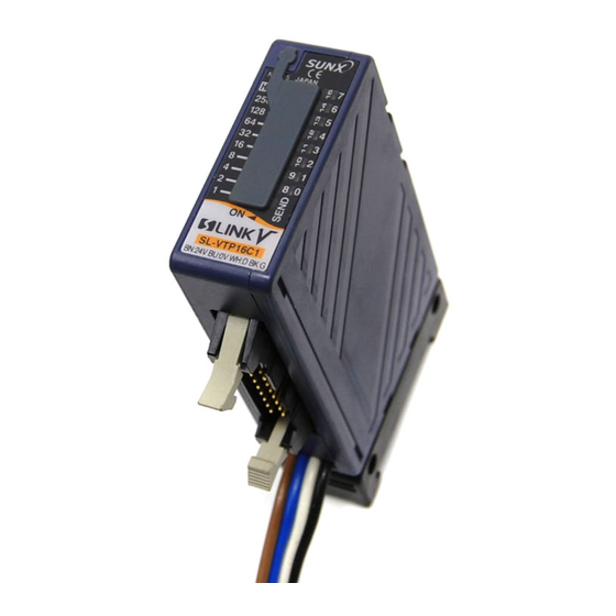
FUNCTIONAL DESCRIPTION
20-pin MIL
16 channel MIL
16 channel MIL
connector (Header)
connector input unit
connector output unit
Conforming to
SL-VT16C1
SL-VTP16C1(-S)
AXM220001
MIL-C-83503
5
4
5
1
mark
(On connector side)
3
2
3
2
Connector I/O unit
mounting base
Description
Function
Input device
I/O device is connected.
SL-VT16C1
c o n n e c t i o n
The above figure shows SL-VT16C1 and SL-VTP16C1.
MIL connector
In case of SL-VTP16C1-S, the direction of the
1
MIL connector is different. For details, refer to
Output device
"
20-PIN MIL CONNECTOR (HEADER) PIN
SL-VTP16C1(-S)
c o n n e c t i o n
ARRANGEMENT."
MIL connector
2
Address setting switch
It is used to set the address.
SL-VT16C1
NOT USED
Not used. (Setting to OFF is recommended.)
Output hold
3
SL-VTP16C1(-S)
function set-
It is used to set the output hold function.
ting switch
Transmission indicator
It blinks to indicate the synchronization signal
4
(Green)
transmission from the S-LINK V controller.
Input indicators
SL-VT16C1
Each lights up when the respective input is ON.
(Green)
5
Output indicators
SL-VTP16C1(-S)
Each lights up when the respective output is ON.
(Orange)
2
MOUNTING
● Use the attached connector I/O unit mounting base to mount the unit.
● In order to fit the connector I/O unit mounting base on the unit, align the
connector I/O unit mounting base with the grooves in the unit body and
slide it till the unit stopper locks.
1. Slide in after aligning with the
2. Make the unit stopper lock.
grooves in the unit body.
Grooves
Unit stopper
● To enable mounting of the unit in different directions, two places for fit-
ting the connector I/O unit mounting base have been provided on the
unit body. Use any one depending upon your requirement.
Mounting 1
Mounting 2
Unit
4-core flat cable
4-core flat cable
Unit
Connector I/O unit
Connector I/O unit
mounting base
mounting base
DIN rail stopper
DIN rail stopper
● In case of mounting on DIN rail or optional mounting bracket MS-DIN-3
1. Fit the rear portion of the connec-
tor I/O unit mounting base on the
35mm width DIN rail or the optional
mounting bracket.
2. Press down the front portion of
the connector I/O unit mounting
base on the DIN rail or the optional
mounting bracket to fit it.
1
* It can be removed by inserting a
flathead screwdriver in the DIN rail
stopper and pulling outwards.
DIN rail stopper
● In case of using screws
• If mounting by screws, use M4 pan
head screws and the tightening
torque should be 0.8N·m or less.
If the unit is mounted on its side,
ensure to mount such that the unit
Connector I/O
stopper is on the top side.
unit mounting base
● If several SL-VT16C1 / SL-VTP16C1(-S), or SL-VT16C1 / SL-VTP16C1(-S)
and other S-LINK V I/O units are used by installing them together, it may not be
possible to install them without a gap, depending on the ambient temperature.
Mount them at a spacing which is equal to or more than the mounting
interval value obtained from the figure below.
4
SL-VT16C1
16
16
To horizontal install the units
To horizontal install the units
Units
12
12
L ≥ 25
L
L = 20
8
8
L = 15
To vertically install the units
To vertically install the units
L = 10
L
L = 5
4
L = 0
4
Units
0
0
-10
0
10
20
30
40
5055
-10
Ambient temperature (ºC)
L = Unit mounting interval (mm)
L = Unit mounting interval (mm)
Note: If SL-VT16C1 and SL-VTP16C1(-S) are mounted together, mount them at the larger of
the unit mounting interval values, L, obtained from the two graphs.
● For example, at an ambient temperature of +40°C, in case the maximum
number of simultaneously ON channels is 16, the unit mounting interval,
L, is as follows:
In case of SL-VT16C1: 17mm or more
In case of SL-VTP16C1(-S): 3mm or more
3
I/O CIRCUIT DIAGRAMS (per channel)
Make sure to connect input devices to SL-VT16C1 and output devices to
SL-VTP16C1(-S). In case of wrong connection, there is a danger of damage.
● 16 channel MIL connector input unit / SL-VT16C1
• Input circuit
+24V
Power supply circuit
D
G
0V
S-LINK V system side
Internal circuit
*1
Non-voltage contact, NPN transistor or DC 2-wire type output
• Input current: 5mA or less
• Operation voltage: ON voltage 17V or more (between input and +24V)
OFF voltage 4V or less (between input and +24V)
• Input impedance: Approx. 6.3kΩ
● 16 channel MIL connector output unit / SL-VTP16C1 (-S)
• Output circuit
+24V
Power supply circuit
D
G
0V
S-LINK V system side
Internal circuit
4
CABLE CONNECTION
Make sure that the power supply is OFF while wiring.
● 4-core flat cable connection
• Use the optional exclusive hook-up connectors when using the exclusive
DIN rail stopper
flat cable for the S-LINK V system's main / branch cable.
• Match the color code of the 4-core main / branch cable and the 4-core
flat cable of SL-VT16C1 or SL-VTP16C1(-S).
2
35mm width DIN rail or
optional mounting bracket MS-DIN-3
Flathead screwdriver
Unit
M4 pan head screw
Please arrange
5
20-PIN MIL CONNECTOR (HEADER) PIN AR-
separately.
RANGEMENT
Make sure to connect input devices to SL-VT16C1 and output devices to
Unit stopper
SL-VTP16C1(-S). In case of wrong connection, there is a danger of damage.
SL-VTP16C1(-S)
Units
L ≥ 10
L
L = 5
L
L = 0
Units
0
10
20
30
40
5055
Ambient temperature (ºC)
20-pin MIL connector (header) pin arrangement
SL-VT16C1
0ch
8ch
1ch
9ch
2ch
10ch
3ch
11ch
4ch
12ch
5ch
13ch
6ch
14ch
7ch
15ch
+24V
+24V
0V
0V
mark
(On connector side)
(Input unit)
+24V
Notes: 1) Please procure the suitable mating connector (socket) separately compliant prod-
uct with MIL-C-83503.
Input
2) Please wire by taking the
*1
Output circuit of
input device
0V
Input device side
+24V
Load
Output
100mA max.
0V
Output device side
6
SPECIFICATIONS
Item
Supply voltage
Current consumption
Main / branch cable
Allowable through
Exclusive hook-up
current (Note 1)
connector
Address setting
Match the
wire colos
Input
4-core flat cable
Unit
Output
Output operation
Short-circuit pro-
mark
tection
(On connector side)
I/O channel No.
Output hold function
Ambient temperature
Ambient humidity
Connector I/O unit
mounting base
Material
Weight
Accessory
Notes: 1) It includes the current consumption of this unit and the connected devices.
2) If the output is short-circuited even for one channel, the short-circuit protection
SL-VTP16C1
SL-VTP16C1-S
works for all the channels and output to the external devices is stopped. Normal
operation is automatically restored when the cause of the short-circuit is removed.
3) If this unit is installed in a control box along with other units, the ambient tempera-
mark
ture may exceed the rated value due to the heat generated by the units. In this
(On connector side)
case, make sure that the ambient temperature does not exceed the rated value by
0ch
8ch
0ch
1ch
installing a fan, etc.
1ch
9ch
2ch
3ch
2ch
10ch
4ch
5ch
7
CAUTIONS
3ch
11ch
6ch
7ch
4ch
12ch
8ch
9ch
5ch
13ch
10ch
11ch
● This product has been developed / produced for industrial use only.
6ch
14ch
12ch
13ch
7ch
15ch
14ch
15ch
0V
0V
0V
0V
8
INTENDED PRODUCTS FOR CE MARKING
+24V
+24V
+24V
+24V
mark
● The models listed under "
(On connector side)
Marking.
As for all other models, please contact our office.
(Output unit)
(Output unit)
mark on the 20-pin MIL connector as the reference.
Please refer to the "S-LINK V User's Manual" for details of the entire
S-LINK V system.
Panasonic Industry Co., Ltd.
1006, Oaza Kadoma, Kadoma-shi, Osaka 571-8506, Japan
https://industry.panasonic.com/
Please visit our website for inquiries and about our sales network.
Panasonic Industry Co., Ltd. 2024
April, 2024
16 channel MIL connector
Type
Input unit
Output unit
SL-VT16C1
SL-VTP16C1 SL-VTP16C1-S
Model No.
24V DC
+10
%
-5
(supplied from the S-LINK V controller or separate power supply)
80mA or less (with all inputs
50mA or less
ON, including input current)
(with all outputs ON)
Total 1.2A or less
0 to 511, settable with switch
Photocoupler input
• Input current: 5mA or less
• Operation voltage:
ON voltage 17V or more
(between input and +24V)
-
OFF voltage 4V or less
(between input and +24V)
• Input impedance:
Approx. 6.3kΩ
NPN open-collector transistor
(photocoupler isolation)
• Maximum sink current:
100mA
• Applied voltage:
30V DC or less
-
(between output and 0V)
• Residual voltage:
1.5V or less
(at 100mA sink current)
0.4V or less
(at 16mA sink current)
Output transistor turns ON
-
when the output signal from the
signal transmission line is ON.
-
Incorporated (Note 2)
16 inputs
16 outputs
-
Incorporated
-10 to +55ºC (No dew condensation or icing allowed) (Note 3)
Storage: -20 to +70ºC
35 to 85% RH, Storage: 35 to 85% RH
Enclosure: ABS, Connector I/O unit mounting base: POM
Approx. 80g
Connector I/O unit mounting base: 1 pc.
SPECIFICATIONS" come with CE
6
PRINTED IN JAPAN
Advertisement

Related Manuals for Panasonic S-LINK V SL-VT16C1


Summary of Contents for Panasonic S-LINK V SL-VT16C1
- Page 1 Total 1.2A or less optional mounting bracket MS-DIN-3 current (Note 1) connector Thank you very much for purchasing Panasonic products. Read this Instruc- * It can be removed by inserting a Address setting 0 to 511, settable with switch tion Manual carefully and thoroughly for the correct and optimum use of this...
- Page 2 S-LINK Vシステム全般の内容については、 『S-LINK Vユーザーズマニュ +24V 負荷 主 アル』をご参照ください。 出力 ユニット 電源回路 回 100mA MAX. コネクタ入・出力 コネクタ入・出力 パナソニック インダストリー株式会社 ユニット取付台 路 ユニット取付台 〒571-8506 大阪府門真市大字門真1006番地 DINレールストッパ DINレールストッパ https://industry.panasonic.com/ <FAデバイス技術相談窓口> TEL:0120-394-205 S-LINK Vシステム側 内部回路 出力機器側 受付時間:平日の9時~12時、13時~17時(土日祝日、年末年始、当社休業日を除く) Panasonic Industry Co., Ltd. 2024 2024年4月発行 PRINTED IN JAPAN...
Need help?
Do you have a question about the S-LINK V SL-VT16C1 and is the answer not in the manual?
Questions and answers