Table of Contents
Advertisement
Quick Links
Advertisement
Table of Contents

Related Manuals for Electron Charger EC-EVC-L3-18KW-G1


Summary of Contents for Electron Charger EC-EVC-L3-18KW-G1
- Page 1 EC-EVC-L3-18KW-G1 DC Fast Charger User Manual & Installation Instructions 18KW...
-
Page 2: Table Of Contents
CONTENT Table of Contents Introductions ..................1 Features Applications..................1 Basic User Interface .............. 2 Main unit 18KW ......................2 Specification ............... 4 Product Specification ............4 Main Size of Charger:18KW ..................5 Installation Instructions ............6 Grounding and Safety Requirements .......... 7 2.2.1 Service Wiring ....................8 Unpack the charger .............. -
Page 3: Introductions
Introductions The Wall Mount DC Fast Charger is the top choice to power battery electric vehicles (BEV) and plug-in electric vehicles (PHEV). It is designed for quick charging in both public and private locations, such as retail and commercial parking spaces, fleet charging stations, highway service areas, workplace, residence, etc. -
Page 4: Basic User Interface
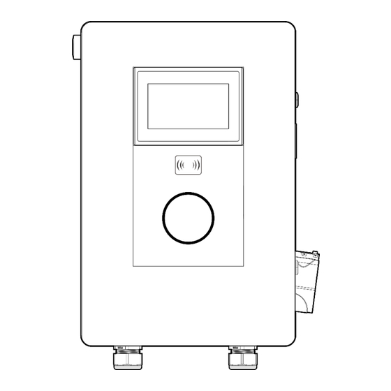
1. Basic User Interface Main unit 18KW... -
Page 6: Specification
1. Specification 1.1 Product Specification EC-EVC-L3-18KW-G1 Model Technical features Max Power Up to 18KW Input/Output power 208VAC±10%- 50/60Hz-3phase Power factor 0.98 Efficiency >95% Measuring accuracy Level 0.5 Output voltage range CCS1: 250~1000VDC Output current range 0-100A Communication User interface RFID card and APP... -
Page 7: Dimensions (Unit: Mm)
2.2 Dimensions (Unit: mm) Main Size of Charger:18KW... -
Page 8: Installation Instructions
2. Installation Instructions 2.1 Before Installation • Read all the instructions before using and installing this product. • Do not use this product if power cable or charging cable has any damage. • Do not use this product if the enclosure or charging connector is broken or open or if there is damage. -
Page 9: Grounding And Safety Requirements
2.2 Grounding and Safety Requirements • The product must be connected to a grounded, metal, permanent wiring system. Connections shall comply with all applicable electrical codes. • Ensure power is disconnected at all times when installing, servicing, or maintaining the charger. •... -
Page 10: Service Wiring
2.2.1 Service Wiring • Ground Connection Always connect the Neutral at the service to Earth Ground. If the ground is not pro- vided by the electrical service then a grounding stake must be installed nearby. The grounding stake must be connected to the ground bar in the main breaker panel and Neutral connected to Ground at that point. -
Page 11: Unpack The Charger
2.3 Unpack the charger WARNING! Charger weight >176Lbs! Be careful during the unpacking process. STEP 1. STEP 2. are packed in a carton. - Page 12 STEP 3. Remove the surrounding cardboard and film. Take out the Charger and Gun holders. User Manual φ6 Expansion M4*40 Screw Pipe (x1) (x6) (x6) Wallbox(x1) RFID CARD (x2) Key (x2) SD card(x1)
- Page 13 2.4 Recommended Tools for Installation and Inspection 2.4.1 Recommended Tools for Installation Type Description Philips Screwdriver No. 2 and 3 Shifting Wrench 8" (24mm) Ball-Head Hex Key 2.5mm and 5mm Socket Screwdriver No. 8 ,10 and 17 Electrical Tape Black / 15mm Width AC Input Cable of 18KW 16mm Cable x 5 (L1,L2,L3,N,PE)
- Page 14 2.5 Installation Procedure Taking 18KW as an example STEP 1. Place the wall-mounted bracket between 600mm (24 inches) and 1.2m (4 feet) above the floor, and then attach 4 pcs 3/8” expansion screws to the wall- mounted bracket. (Unit: mm) Unit: mm STEP 2.
- Page 15 STEP 3. Screw 2 sets M6 screws to the bottom of the charger to fix the charger on the bracket. STEP 4. Keep the hook-shape holders as cable holder or disassemble them if not necessary.
- Page 16 Installing the AC Input Connect STEP 5. 18KW...
- Page 17 STEP 6.
- Page 18 STEP 7.
-
Page 19: Installation Inspection & Commissioning
2.6 Installation Inspection & Commissioning 2.6.1 Environmental Check Item Status Remark Ambient Temperature Ambient Humidity Recommended but not Sunshade required. Recommended but not Rain Canopy required. Air Circulation / Drafty Dust Level Anti-Vandalism Measures 2.6.2 External Infrastructure Readiness & Check Item Status Remark... - Page 20 2.6.3 EVSE Check – Static (Non-Powered) Item Status Remark Outlook Labeling & Warning Signs Package (Accessory) List Robustness of Input Wirings 2.6.4 EVSE Check - Power On Item Status Remark Screen On Acoustic Noise Screen Display & Function Time Display Correctly Network Connection Quality Cooling Fans Operation &...
- Page 21 2.6.5 EVSE Check - Charging Item Status Remark User Authorization –RFID User Authorization –QR Code User Authorization –Others. Waiting Time of Connection Check Reading of Each Display Item Full Charge Test Function of Electronic Lock Reading of Engineer Mode Airflow & Noise of Cooling Fan Charging Record ( log ) Upload Remote Control &...
-
Page 22: Network Setting
3. Network Setting 4.1 Wi-Fi Network Setting Laptop with RJ45 interface. Connect RJ45 cable from Laptop to charger ’ s RJ45 port. Setup parameters in the Webservice. Step 1. Open web service browser, type the IP address of charger“192.168.2.5:8080” into the URL bar to access the web page of charger. - Page 23 Step 2. Select Wi-Fi Module Select Wi-Fi modes and fill in SSID and Password according to your application, if not required, just keep default.
-
Page 24: Operation Process
4. Operation Process 5.1 RGB LED indicators Charger status LED performance Standby green blink plug in yellow swipe/punch a card yellow charging Light green breath Fault status Red flashing 5.3 LCD indicators the EMN series config a 7-inch LCD screen, which is mainly used to display various status information of the charging station. - Page 25 In Fig. 1-2, there are three areas to display icons or instructions, with the specific meanings as follows: Icon Description Area ① Connected a network through 4G cellular Connected a network through WIFI Connected a network through Ethernet Area ② Version Software version Serial number of EVSE...
- Page 26 Fig. 6-4 Display of Charging Fig. 6-5 Display of Finished...
- Page 27 ◼ Click the settings icon three times to enter the settings interface, the picture displayed on the LCD screen is shown in Fig. 6-6. ◼ Enter password: 1234 Fig. 6-6 Display of Management...
-
Page 28: Troubleshooting
◼ If the charging process fails or the equipment fails, the picture displayed on the LCD screen is shown in Fig. 6-7. Fig. 6-7Display of fault state 4.1 Troubleshooting • Please follow the instructions in the table when errors occur during the charging process. - Page 29 Status Description Solution Code 0001 Emergency stop If no fault occurs,please rotate the button clockwise to reset the charger. 0002 CCS output fuse blew If fault occurs,please check&replace the fuse. 0003 AC input contactor 1 welding If fault occurs,please check&replace the contactor.
-
Page 30: General Maintenance
5. Maintenance 5.1 General Maintenance • The DC Fast Charger is cooled by forced air. Please keep the charger in a ventilated location and do not block the air vents of the DC Fast Charger. • Please clean or replace the air filters regularly to ensure the DC Fast Charger works properly. -
Page 31: Limited Product Warranty
fire. • Flood, pest damage, abuse, accident, misuse, negligence, or failure to maintain the product or other event beyond Electron Charger’s reasonable control or not arising from normal operating condition. • Cosmetic or superficial defect, dents, marks or scratches after use. -
Page 32: Appendix - Package List
Appendix - Package list Item Description Quantity Remark EVSE User Manual OQC Report RFID Card Key of Cabinet Wall-Mounted Bracket Single Gun*1pcs, Gun Holder Dual Gun*2pcs Refer to Chapter 2.2 Table 5/16” Expansion Screw Each Gun Holder*2pcs 3/8” Expansion Screw Wall-Mounted Bracket*4pcs 10 M6 Screw Wall-Mounted Bracket*2pcs... - Page 33 NOTE...
Need help?
Do you have a question about the EC-EVC-L3-18KW-G1 and is the answer not in the manual?
Questions and answers