Table of Contents
Advertisement
Quick Links
Advertisement
Table of Contents

Related Manuals for Electron Charger EC-EVC-L3-30KW-G1


Summary of Contents for Electron Charger EC-EVC-L3-30KW-G1
- Page 1 EC-EVC-L3-30KW-G1/G2 DC Charger Installation Guide Model No. EC-EVC-L3-30KW-G1/G2...
-
Page 2: Table Of Contents
CONTENT Applications ......................1 1. Basic User Interface ..................2 2. Specification .....................4 2.1 Product Specification ................4 3. Installation Instruction .................7 Before Installation ..................7 3.1 Grounding and SafetyRequirement ........... 8 3.2 Service Wiring ..................9 3.3 Unpack the charger ................10 3.5 Accessory .....................12 3.9 Installation Inspection &... -
Page 3: Applications
Introductions The EC-EVC-L3 DC Fast Charger is the top choice to power battery electric vehicles (BEV) and plug-in electric vehicles (PEV). It is designed for quick charging both public private locations, such retail and commercial parking spaces, fleet charging stations, highway service areas, workplace, residence, etc. -
Page 4: Basic User Interface
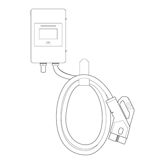
1. Basic User Interface DC 30kW... -
Page 5: Specification
2. Specification 2.1 Product Specification EC-EVC-L3-30KW-G1/G2 Model Technical features Power Input Up to 30kW 480VAC ± 10% Input/Output power 45-65Hz - 3phase Power factor 0.98 Efficiency >98% Measuring accuracy Level 0.5 Output voltage range CCS: 300~1000VDC 0-100A Output current range Communication Ethernet / WIFI / 4G / OCPP 1.6 J (TLS) - Page 6 2.2 Dimensions DC30 kW...
-
Page 7: Installation Instruction
3. Installation Instruction Before Installation • Read all the instructions before using and installing this product. • Do not use this product if power cable or charging cable have any damage. Do not use this product if the enclosure or charging connector are broken or open •... -
Page 8: Grounding And Safetyrequirement
3.1 Grounding and Safety Requirement • The product must be connected to a grounded, metal, permanent wiring system. Connections shall comply with all applicable electrical codes. • Ensure no power is connected at all times when installing, servicing, or maintain- ing the charger. -
Page 9: Service Wiring
3.2 Service Wiring Ground Connection: Always connect the neutral at the service to earth ground. If ground is propvided by the electrical service then a grounding stake must be installed nearby. The grounding stake must be connnected to the ground bar in the main breaker panel and neutral connected to ground at that point. -
Page 10: Unpack The Charger
3.3 Unpack the charger WARNING! Be!careful!during!unpack!process. STEP 1: Remove the surrounding boards STEP 2: Remove the packaging film and the paper cover. Accessories (wall mount) are packed in a carton. - Page 11 STEP 3: Remove the surrounding cardboard and film. Take out the Charger and Gun holders. STEP 3.
-
Page 12: Accessory
3.4 Accessory User Manual φ6 Expansion M4*40 Screw Pipe (x1) (x6) (x6) Wallbox(x1) RFID CARD (x2) Key (x2) SD card(x1) - Page 13 3.5 Tools for Mounting Type Description Philips Screwdriver No. 2 and 3 Shifting Wrench 8" (24mm) Ball-Head Hex Key 2.5mm and 5mm Socket Screwdriver No. 8 ,10 and 17 Electrical Tape Black / 15mm Width AC Input Cable of 30KW 16mm Cable x 5 (L1,L2,L3,N,PE) AC Input Cable of 40KW...
- Page 14 3.6 Tools for Inspection Type Description EV or EV Simulator Meet CCS2 standard Multiple Meter 1000V Current Probe 100Amp RFID Authorized Card RFID No Valid Card Door Key Needle-Nose Plier Laptop or PC & CAT6 cable For Charger Configuration...
- Page 15 3.7 Mounting on the wall or pedestal STEP 1. Place the wall-mounted bracket between 600mm (24 inches) and 1.2m (4 feet) above the floor, and then attach 4 pcs 3/8”expansion screws to the wall-mounted bracket. STEP 2. Install the four tenons on the rear side of the charger into the grooves on the wall-mounted bracket.
- Page 16 STEP 3. Screw 2 sets M6 screws to the bottom of the charger to fix the charger on the bracket. STEP 4. Keep the hook-shape holders as cable holder or disassemble them if not necessary.
- Page 17 STEP 5. Please use XLPE power cables or equivalent for AC input connection, power cable outer diameter is between 32 and 40mm. Each wire shall be crimped with the corresponding terminal before feeding. And then feeding the cable from bottom side and passing through the cable gland. L1, L2, L3, N, and PE are connected to the docking terminals as shown in the figure below.
-
Page 18: Installation Inspection & Debuging
3.8 Installation Inspection & Debugging Description Status Remark Environment Ambient Temperature Ambient Humidity Sunshade Recommended but not required. Rain Canopy Recommended but not required. Air Circulation / Drafty Dust Level Anti-Vandalism Measures External Infrastructure Input Wirings & Terminals Type/ Length/ Cross Section Key &... - Page 19 Network Connection Quality Cooling Fans Operation & Noise Led Status Indication EVSE Setting Function of Engineer Mode Version of H.W. & F.W. Remote Control & Monitoring Backend Server Connection EVSE Charging User Authorization –RFID User Authorization –QR Code User Authorization –Others. Waiting Time of Connection Check Reading of Each Display Item...
-
Page 20: Operation Process
4. Operation Process 4.1 Network Setting Wi-Fi Network Setting Laptop with RJ45 interface. Connect RJ45 cable from Laptop to charger ’ s RJ45 port. Setup parameters in the Webservice. Step 1. Open web service browser, type the IP address of charger“192.168.2.5:8080” into the URL bar to access the web page of charger. -
Page 22: Troubleshooting
Step 2. (1)Select Wi-Fi Module Select Wi-Fi modes and fill in SSID and Password according to your application, if not required, just keep default. (2)Version number, charging pile number Server address can be changed&set; Step 3. Set the number and type of charging piles, Module type and number. - Page 23 Error List Screen Description Solution Show Rotate the button clockwise to reset Emergency stop the charger CCS output fuse blew Replace the fuse AC input contactor 1 welding Replace the contactor CCS output relay welding Replace the Relay CCS connector temperature sensor Replace the sensor broken Relay control module /smart box...
-
Page 24: Maintenance
5. Maintenance 5.1 General Maintenance • The DC Fast Charger is cooled by forced air. Please keep charger in a ventilated location and do not block the air vents of the DC Fast Charger . • Please clean or replace the air filters regularly to ensure the DC Fast Charger works properly. - Page 25 Note: • Before switching off main breaker to begin maintenance, please record the status code number on the LCD monitor. After switching off the key switch the circuit before the main terminal is still • hazardous. Only visual inspection can be operated. •...
Need help?
Do you have a question about the EC-EVC-L3-30KW-G1 and is the answer not in the manual?
Questions and answers