Table of Contents
Advertisement
Quick Links
Advertisement
Table of Contents

Related Manuals for Altair IPCOM IPX-301

Summary of Contents for Altair IPCOM IPX-301
- Page 1 IPcom Series Digital Intercom Audio Interface Over IP ALTAIR IPCOM IPX-301 2W-4W Intercom Audio Interface USER MANUAL March 2023 version AUDIO | BROADCAST | COMMUNICATION PRODUCTS www.altairaudio.com COPYRIGHT Equipos Europeos Electrónicos...
-
Page 2: Table Of Contents
2W Compatibility............................10 Use Cases.......................... 11 Altair IPcom Software......................13 Advanced Settings............................. 16 Technical Specifications..................... 18 Appendix OR-1-301 RACK ACCESSORY FOR ALTAIR IPX-301..............19 WARRANTY........................20 Contact and Links.......................22 Included in the supply 1x IPX-301 One channel IP >< Intercom/Analogue audio 2x 3 pin 3.50 Euroblock connectors... -
Page 3: Introduction
/ 12 KHz (Lower Quality). Like the rest of the Altair IPcom Series device, the NEBULA Configuration Software will be used to assign intercom groups, define the different audio levels and configure all the parameters of the unit. Up to 6 intercom groups (Party-Line, One-To-Many) can be assigned at the same time. - Page 4 ALTAIR IPcom Series: Model IPX-301 INTRODUCTION The control of the Input Gain and Output Level levels is independent of the operating mode (2W Mode / 4W Mode) in which the IPX-301 unit is configured through NEBULA IpCom Configuration Software. A single control is available to adjust the Input Gain which will affect the input of all channels.
-
Page 5: Front Panel
ALTAIR IPcom Series: Model IPX-301 HARDWARE Front Panel The front panel of the IPX-301 Interface contains the following elements: Controls GPO Port (A) Fitted standard (3.5 pitch) Phoenix™ connector for General Purpose Output signals. The IPX- 301 includes 1 general purpose logic output. This GPO has a relay that commutes when it gets activated. - Page 6 ALTAIR IPcom Series: Model IPX-301 HARDWARE F1 Key (C) F1 is a programmable key to which the user can assign an action of their choice. The available options are: Key (to act remotely on a key of another device), GPIO (acts on a GPIO of the selected user) and Function (to carry out actions such as: Call to Group, Mic Kill to User, Mic Kill to Group, Buzzer Kill to User, Buzzer Kill to Group and Replay Last Seconds).
-
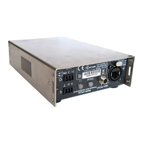
Page 7: Rear Panel
Input Attenuator switch. Positons 0/ -20 dB. Set it to -20 dB for normal operation (default). Set to 0 dB for weak signal inputs. MODE Selection Button (D) Button that allows switching between 2-Wire Mode (Altair and others wired/wireless Intercom Systems) and 4-Wire Mode (for standard systems based on four-wire input/output analog audio). Power LED (E) Indicates the power status of the XLR Intercom line whereas it comes from an external powered base (BASE mode) or generated internally when PW (power) is active (BELTPK mode). - Page 8 Base Mode and Beltpack Mode. - Base Mode (BASE) power OFF, used to connect to complete wired/wireless intercom systems. Equivalent to the SLAVE mode of Altair base stations (in previous series) when connected to a complete system. - Beltpack Mode (BELTPK) power ON, it allows to supply up to 5 wired beltpacks without the need of a base station or power supply.
-
Page 9: Operation
ALTAIR IPcom Series: Model IPX-301 Operation Interface turn-on The IPX-301 interface stations as well as the rest of the devices of the Ipcom series do not have a power button and their operation is subject to the switch-on of the switch to which they belong. -
Page 10: Talk
ALTAIR IPcom Series: Model IPX-301 Then go to the unit that you want to set as controller and set one channel as Remote in the TYPE column of the Channel Config tab. Then set the device you want to control, in this case the IPX-301 in the USER/CUE/GROUP tab Talk The Talk concept in this device refers to the signal entering the interface. -
Page 11: Listening Volume
ALTAIR IPcom Series: Model IPX-301 Listening volume As a not attended device, the interface has not front panel level controls and settings must be carried out by accessing to NEBULA soft or by setting one of the interface channels in remote, controlled by other IPcom unit. -
Page 12: Call Interfacing
The CALL properties as time period of call signaling and pulses are similar to the classic Altair intercom. In both cases, it is possible to configure the channel in the NEBULA Users window to permit CALL sending and receiving. -
Page 13: Use Cases
The example shows how the elements must be connected to use the IPX-301 unit as a communication bridge between an Altair IPcom System and an Altair Wireless System with a Dual Channel Base Station and four WBP-200HD (with two beltpacks configured in Channel A and the other two beltpacks on Channel B). - Page 14 The example shows how the elements must be connected to use the IPX-301 unit as a communication bridge between an Altair IPcom System and an Intercom Matrix Panel port from A third party manufacturer. The IPX-301 unit must be configured in 4W Operating Mode. The wiring connection will be as follows: - ETHERNET/PoE Connector ======>...
-
Page 15: Altair Ipcom Software
NEBULA CONFIGURATION SOFTWARE Altair IPcom Software Configuration windows The configuration software for the entire ALTAIR IPcom Series contains 6 main windows: Groups (A) It shows all the groups created in the system, indicates the different devices that belong to each group and allows assigning a group configuration for each particular device. - Page 16 ALTAIR IPcom Series: Model IPX-301 NEBULA CONFIGURATION SOFTWARE Users Groups (C) It shows a “matrix” with all the devices and groups of the system, indicating which groups each device is assigned to. If the user has a group assigned to any of their channels, a circle of the same color as the group will be shown in the corresponding column.
- Page 17 ALTAIR IPcom Series: Model IPX-301 NEBULA CONFIGURATION SOFTWARE Users Cues (E) It shows a “matrix” with all the devices and Cues of the system, indicating which devices each Cue is assigned to and its status. Double clicking on a cell will assign the corresponding the CUE on the selected device.
-
Page 18: Advanced Settings
ALTAIR IPcom Series: Model IPX-301 NEBULA CONFIGURATION SOFTWARE Advanced Settings IPX-301 Interface Advanced Settings Window The window gives access to the complete configuration of the IPX-301 Interface. The window contains 3 tabs that show the different configuration parameters available: General (A) - Page 19 ALTAIR IPcom Series: Model IPX-301 NEBULA CONFIGURATION SOFTWARE Ethernet (C) Allows you to activate/deactivate DHCP and, where appropriate, allows you to assign a static IP to selected IPX-301. Note: For further information on the operation of the Configuration Software, review the specific manual.
-
Page 20: Technical Specifications
ALTAIR IPcom Series: Model IPX-301 TECHNICAL SPECIFICATIONS Technical Specifications TECHNICAL SPECIFICATIONS NUMBER OF CHANNELS 1x ANALOGUE to IP (6 x groups) FREQUENCY RESPONSE 100 Hz – 10 KHz (-3 dB) DYNAMIC RANGE 80 dB SYSTEM SPECIFICATIONS SIDE-TONE CANCELLATION (2W) Automatic (Auto-NULL) ●... -
Page 21: Appendix Or-1-301 Rack Accessory For Altair Ipx-301
Appendix OR-1-301 RACK ACCESSORY FOR ALTAIR IPX-301 ASSEMBLY INSTRUCTIONS: 20 mm 130 mm 240 mm 1. Attach the IPX-301 using 4 M3x5 screws, 2 at the front and 2 at the rear of both IPX-301s (Figure 1). 2. Remove the original side screws of the IPX-301´s located at the ends (Figure 2). -
Page 22: Warranty
Altair expressly disclaims any responsibility for such usage which shall be made at your sole risk, even if Altair has been informed in writing of such usage. Unless expressly designated in writing by Altair as suitable for use in aerospace applications, you shall not use the above products in... - Page 23 European Union Waste Electronics Information Unión Europea Información sobre residuos electrónicos Waste from Electrical and Electronic Equipment (WEEE) directive The WEEE logo signifies specific recycling programs and procedures for electronic products in countries of the European Union. We encourage the recycling of our products. If you have further questions about recycling, contact your local sales office.
-
Page 24: Contact And Links
Contact and Links _______________________________________ Web Page www.altairaudio.com _______________________________________ Social Media : /AltairAudio : /AltairAudio : /AltairAudio : /AltairAudio : @AltairAudio : @AltairAudio _______________________________________ Product catalog www.altairaudio.com/products _______________________________________ Technical Support Contact: +34 918043265 _______________________________________ AUDIO | BROADCAST | COMMUNICATION PRODUCTS www.altairaudio.com COPYRIGHT Equipos Europeos Electrónicos...
Need help?
Do you have a question about the IPCOM IPX-301 and is the answer not in the manual?
Questions and answers