
Related Manuals for Srne ABP4840U100-H


Summary of Contents for Srne ABP4840U100-H
- Page 1 User Manual Solar storage inverter ABP4840U100-H ABP4850U120-H ABP4860U140-H ABP4865U140-H Version:V1.1...
-
Page 2: Table Of Contents
Contents 1. Safety .............................1 1.1 About this Manual .............................1 1.2 Symbols and description .........................1 1.3 Safety matters ............................. 1 2. About the Product ....................... 2 2.1 Description ..............................2 2.2 Features .................................2 2.3 System connection diagram ........................3 2.4 Product overview ............................4 3. - Page 3 5.1 Operation and display panel .......................37 5.2 Setting ................................. 42 5.3 Timed charge/discharge function ..................... 51 5.4 Battery parameters ..........................52 6. Communication ........................54 6.1 USB-B port ..............................54 6.2 WIFI port ..............................54 6.3 RS485/CAN port ............................55 6.4 CT port (option) ............................55 6.5 Dry contact port ............................56 7.
-
Page 4: Safety
1. Safety 1.1 About this Manual This Manual contains important information, guiding principles, operation, and maintenance of the product, and applies to the model: ABP U series Users must follow the instructions in this Manual during installation, use and ... -
Page 5: About The Product
2. About the Product 2.1 Description ABP series is a new type of solar storage inverter that integrates PV storage, mains charge, and energy storage and outputs sinusoidal AC. Equipped with DSP control and advanced control algorithm, it has high response speed and good reliability, and applies to industrial scenarios. -
Page 6: System Connection Diagram
2.3 System connection diagram The following figure shows the system application scenario of the product. A complete system consists of the following parts: PV module: It converts solar energy into DC to charge batteries or into AC to supply power to loads. Mains or generator: Connected to AC input, it can charge batteries while supplying power to loads. -
Page 7: Product Overview
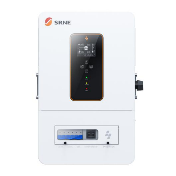
2.4 Product overview LCD screen Physical button LED indicator Circuit breaker cover PV input Battery (positive electrode) Generator Battery (negative electrode) Load (L1+L2+N) input(L1+L2+N) Grid (L1+L2+N) Dry contact RS485/CAN port WIFI port USB-B port 16 Parallel communication port 17 Grounding screw PV Circuit breaker ON/OFF rocker switch... - Page 8 Dimension...
-
Page 9: Installation
3. Installation 3.1 Installation location ABP series is only for indoor use (protection level: IP20). Before selecting the installation location, users should consider the following factors: A solid wall Installation height: flush with the line of sight Sufficient heat dissipation space ... -
Page 10: Packing List
3.2 Packing list Pictures Description Quantity Inverter 1pcs M6*60mm 2pcs Expansion screw M5*30mm Plastic expansion 2pcs screw Phillips screw 2pcs M6*10mm Backup screw 2pcs M6*10mm SC35-6 2pcs Copper lug Black screw 4pcs M3X6mm... - Page 11 Parallel communication 1pcs cable WIFI logger 1pcs (optional) 2pcs (optional) User manual 1pcs The warranty card 1pcs Quality Certificate 1pcs Outgoing inspection 1pcs report...
-
Page 12: Inverter Installation
3.3 Inverter installation Drill 4 installation holes of the specified sizes on the wall with an electric drill, insert 2 expansion screws above, and fix the inverter with 2 M5 screws below. 3.4 Removal of terminal cover and insect-proof net ○... -
Page 13: Wiring
4. Wiring 4.1 Wiring mode (depends on the output mode) Split-phase mode (default) Item Description Applicable model ABP series U model AC output phase voltage (L-N) 100 VAC−120 VAC, 120 VAC (default) AC output line voltage (L-L) 200 VAC−240 VAC, 240 VAC (default) Single-phase mode ... -
Page 16: Cable And Circuit Breaker Model
4.2 Cable and circuit breaker model INPUT Inverter Model Cable Size Maximum Input Current Circuit Breaker Model ABP4840U100-H ABP4850U120-H /12AWG 18A/18A 2P-25A ABP4860U140-H ABP4865U140-H Grid input Circuit Output Maximum Inverter Model Diagram Cable Size Breaker Mode Current Model... - Page 17 Circuit Output Maximum Inverter Model Diagram Cable Size Breaker Mode Current Model Split-phase 40A(L1/L2/ 10mm /8AWG 3P-40A mode (L1\L2\N) ABP4840U100-H Single-pha 40A(L1/L2) 10mm /8AWG(L1/L2) 2P-80A se mode 80A(N) 16mm /6AWG(N) Split-phase 40A(L1/L2/ 10mm /8AWG 3P-40A mode (L1\L2\N) ABP4850U120-H Single-pha...
- Page 18 10mm /8AWG(L1/L2) Single-pha 40A(L1/L2) 2P-80A se mode 80A(N) 16mm /6AWG(N) Battery Inverter Model Cable Size Maximum Current Circuit Breaker Model ABP4840U100-H 120A 2P-160A 35mm /2AWG ABP4850U120-H 130A 2P-160A 35mm /2AWG ABP4860U140-H 150A 2P-160A 35mm /2AWG ABP4865U140-H 150A 2P-160A 35mm...
- Page 19 Split-phase 40A(L1/L2/ 10mm /8AWG 3P-40A mode (L1\L2\N) ABP4860U140-H Single-pha 40A(L1/L2) 10mm /8AWG(L1/L2) 2P-80A se mode 80A(N) 16mm /6AWG(N) Split-phase 40A(L1/L2/ 10mm /8AWG 3P-40A mode (L1\L2\N) ABP4865U140-H Single-pha 40A(L1/L2) 10mm /8AWG(L1/L2) 2P-80A se mode 80A(N) 16mm /6AWG(N) ○ ! NOTICE PV input, AC input, and AC output terminals ...
-
Page 20: Grid 、Load And Gen Wiring
4.3 GRID 、LOAD and Gen wiring Connect the live wire, neutral wire, and ground wire according to the cable position and sequence shown in the following figure. GRID: LOAD: Generator: △ DANGER Before connecting AC input and output, be sure to disconnect the circuit breaker to ... -
Page 21: Battery Wiring
4.4 Battery wiring Connect the positive and negative cables of the battery according to the cable position and sequence shown in the following figure △ DANGER Before connecting the battery, be sure to disconnect the circuit breaker to avoid the ... -
Page 22: Pv Wiring
4.5 PV wiring Connect the positive and negative terminals of the two-channel PV modules according to the cable position and sequence shown in the following figure. △ DANGER Before connecting PV modules, be sure to disconnect the circuit breaker to avoid the risk of ... -
Page 23: Grounding
4.7 Grounding Please ensure that the grounding terminal is reliably connected to the grounding busbar. ○ ! NOTICE The grounding cable size shall not be less than 4 mm² and shall be as close as possible to the grounding point 4.8 Inverter start After confirming reliable wiring and correct wiring sequence, restore the terminal cover to its original position... -
Page 24: Cautions For Parallel Connection
4.9.2 Cautions for parallel connection Warning: 1. PV wiring: In parallel connection, the PV array of each inverter must be independent, and the PV array of PV1 and PV2 for one inverter must also be independent. 2. Battery wiring In single-phase or three-phase parallel connection, all solar storage inverters must be connected to the same battery, with BAT+ connected to BAT+ and BAT- to BAT-, and before power on and start-up, it is necessary to check and ensure correct connection, wiring length, and cable size, so as to avoid the abnormal operation of parallel system... -
Page 25: 3Wiring Diagram For Single-Phase Parallel Connection
7. After the system is correctly wired, powered on, and in normal operation, if a new inverter needs to be connected, make sure to disconnect the battery input, PV input, AC input and AC output, and that all solar storage inverters are powered off before reconnecting into the system. - Page 26 Three parallel-connected solar storage inverters: Four parallel-connected solar storage inverters:...
- Page 27 Five parallel-connected solar storage inverters: Six parallel-connected solar storage inverters:...
-
Page 28: Wiring Diagram For Two-Phase Parallel Connection
4.9.4 Wiring diagram for two-phase parallel connection (phase difference between L1 and L2: 0°) (1) P1: Set the item [31] to "2P0;" P2: Set the item [31] to "2P1," all of the P1/P2 inverter item [68] can not be set, it is default “0°”and the phase difference between P1 and P2 is 120°. When setting the item [38] to "120 V,"... - Page 29 Split-phase system (three inverters) 2+1 system Split-phase system (four inverters) 3+1 system:...
- Page 30 2+2 system: Split-phase system (five inverters) 4+1 system:...
- Page 31 3+2 system: Split-phase system (six inverters) 5+1 system:...
- Page 32 4+2 system: 3+3 system:...
-
Page 33: Wiring Diagram For Split-Phase Parallel Connection
4.9.5 Wiring diagram for split-phase parallel connection (phase difference between L1 and L2: 180°) Set the item [31] to PAL, and set the item [68] to 180°. When setting the item [38] to "120 V," the L1-L2 voltage is 240 V, and the L1-N voltage is 120 V, L2-N voltage is 120V Two parallel-connected solar storage inverters: Three parallel-connected solar storage inverters:... - Page 34 Four parallel-connected solar storage inverters: Five parallel-connected solar storage inverters: Six parallel-connected solar storage inverters:...
-
Page 35: Wiring Diagram For Three-Phase Parallel Connection
4.9.6 Wiring diagram for three-phase parallel connection P1: Set the item [31] to "3P1;" P2: Set the item [31] to "3P2;" P3: Set the same to "3P3", all of P1/P2/P3 inverters item [68] can not be set, it is default “0°” At this point, the P1-P2, P1-P3, and P2-P3 phase difference is 120°. - Page 36 Three-phase system (four inverters) 2+1+1 system: Three-phase system (five inverters) 3+1+1 system: 2+2+1 system:...
- Page 37 Three-phase system (six inverters) 2+2+2 system:...
- Page 38 3+2+1 system: 4+1+1 system:...
- Page 39 Note: 1) Before powering on and lighting up the screen, check for correct wiring according to the above wiring diagrams to avoid system problems. 2) Check all connections for firm fixing to avoid detachment and abnormal system operation. 3) When connecting the AC output to the load, complete wiring according to the requirements of the electrical load to avoid damage to the load.
-
Page 40: Operation
5. Operation 5.1 Operation and display panel The operation and display panel of the inverter includes one LCD screen, three indicators, and four physical buttons Physical button Physical button Description Enter/Exit the setup menu Go to the next option Go to the previous option Confirm/Enter the option in setup menu LED indicator... - Page 41 Display screen Icon Description Icon Description PV panel Mains Battery Generator The inverter is working Load The inverter is communicating with The buzzer is in mute mode the data collector Power flow direction The inverter is working The inverter is in standby mode normally There is a fault Settings...
- Page 42 Icon Description Icon Description Load power: 5%−19% SOC: 5%−19% Battery under-voltage Battery over-discharge Overload BMS fault System communication error System under-voltage System overvoltage Too low system temperature Too high system temperature System overcurrent Battery full power User-defined battery Sealed lead-acid battery Flooded lead-acid battery Gel lead-acid battery Ternary Li-ion battery...
- Page 43 Real-time parameters view operation On the screen, press the UP/DOWN button to view real-time data of the inverter in...
- Page 44 Page Battery AC input Load General Mains input Single-phase PV input voltage Battery voltage Current time voltage voltage Mains input Single-phase PV input current Battery current Current date current current Mains total Single-phase PV gross PV input power Battery voltage input power active power generation...
-
Page 45: Setting
5.2 Setting... - Page 46 Parameter Option Description The voltage setting logic: 【15】<【12】<【04】<【14】<【35】<【37】<【05】<【09/11】 (When the battery communicate with inverter, the voltage setting is useless ) Exit Exit the setup menu Photovoltaic energy priority with the load, photovoltaic is not enough, the grid power and photovoltaic mixed load, photovoltaic energy is enough with the load, the excess energy to charge the UTI (default) battery, the grid power only starts charging when the battery is too...
- Page 47 Description only the PV charge mode can be enabled during inverter operation. Do not enable the mains charge mode when in only PV charge mode ABP4840U100-H setting range:0-100A ABP4850U120-H setting range:0-120A Battery charge current ABP4860U140-H setting range:0-140A ABP4865U140-H setting range:0-140A...
- Page 48 Parameter Option Description delay time Battery When the battery voltage is lower than the threshold, it will give an under-voltage alarm under-voltage alarm and the output will not shut down. Setting threshold range: 40 V−52 V, with a step of 0.4 V When the battery voltage is lower than the value, the output Battery discharge immediately shuts down.
- Page 49 Inverter to bypass overload switch Enable auto switch to mains for loading in case of inverter ENA ( default overload ABP4840U100-H setting range:0-60A ABP4850U120-H setting range:0-60A 28 Grid charge current ABP4860U140-H setting range:0-80A ABP4865U140-H setting range:0-80A RS485 communication ID: 1 Setting range: 1−254...
- Page 50 485 or CAN in item 32 communication PAC = PACE, RDA = Ruida, AOG = Aoguan, OLT = Oliter, HWD = Sunwoda, DAQ = Daqin, WOW = SRNE, PYL = Pylontech, UOL = Vilion Disable this function (default Limit power to CT...
- Page 51 Parameter Option Description Period-2 battery 00:00:00 Setting range: 00:00:00−23:59:00 charge end time Period-3 battery 00:00:00 Setting range: 00:00:00−23:59:00 charge start time Period-3 battery 00:00:00 Setting range: 00:00:00−23:59:00 charge end time DIS ( Disable the function default After the timed mains charge/loading function is enabled, the power supply mode will turn into SBU, where mains is available for power supply in the set period or after battery over-discharge.
- Page 52 L1-N/L2-N is 120 V, and the voltage of L1-L2 is 240 V Without N-wire(When you set”No N”,the phase difference is NO N 180° default) Insulation DIS default Disable detecting insulation impedance value. impedance detection Enable detecting insulation impedance value. ABP4840U100-H setting range:0-60A Max charging current by generator ABP4850U120-H setting range:0-60A...
- Page 53 Parameter Option Description ABP4860U140-H setting range:0-80A ABP4865U140-H setting range:0-80A Generator input setting range:0-10KW power CT ratio When connect an external CT, enter the current ratio according to CT 1000 specification. (optional) Anti-reflux Error 100W Setting range 0-500w calibration power DIS( Disable AFCI check function default AFCI check...
-
Page 54: Timed Charge/Discharge Function
5.3 Timed charge/discharge function ABP series has the timed power charge/discharge function. Users can set different charge and discharge periods according to the local time-of-use price, thus reasonably using mains and PV power. When mains is expensive, the battery inverter is used to supply power to the load; when mains is cheap, it can be used to supply power to and charge the load, thus helping users reduce electricity expenses to the full extent. -
Page 55: Battery Parameters
5.4 Battery parameters Lead-acid battery Battery type Sealed lead Gel lead Flooded lead User-defined acid battery acid battery acid battery Adjustable (USE) Parameters (SLD) (GEL) (FLD) Overvoltage disconnection voltage Battery fully charged √ recovery point Boost charge voltage 57.6V 56.8V 57.6V 40~60V... - Page 56 Li-ion battery Battery type Ternary Ternary LFP (L16) Adjustable (N13) (N14) (L15) (L14) Parameters Overvoltage disconnection voltage Battery fully charged 50.4V 54.8V 53.6V 50.4V 47.6V √ recovery point Equalizing charge √ voltage Boost charge voltage 53.2V 57.6V 56.8V 53.2V 49.2V √...
-
Page 57: Communication
Users can use the upper computer software through the port to read and modify device parameters. If needing the installation package for the upper computer software, you can download it from the official website of SRNE, or contact us to get it. 6.2 WIFI port The WIFI port is used to connect to the Wi-Fi/GPRS data acquisition module, and then users can view the operation status and parameters of the inverter via the mobile APP. -
Page 58: Rs485/Can Port
6.3 RS485/CAN port The RS485/CAN port is used to connect to the BMS of the Li-ion battery. RJ45 Definition Pin 1 RS485-B Pin 2 RS485-A Pin 3 Pin 4 CANH Pin 5 CANL Pin 6 Pin 7 RS485-A Pin 8 RS485-B 6.4 CT port (option) Please contact us for firmware and CT if you need this function... -
Page 59: Dry Contact Port
6.5 Dry contact port The dry contact port has 4 functions: 1. RSD power supply Remote ON/OFF 3. Battery temperature sampling 4. Remote generator start/stop Function Description RSD power supply PIN 1 is GND,PIN 2 is RSD 12V+ When pin 1 is connected to pin 3, the inverter will turn off the AC output. Remote ON/OFF When disconnected, the inverter is in normal output. -
Page 60: Fault Codes And Response Measures
7. Fault Codes and Response Measures 7.1 Fault codes Fault Code Alarm Affect Fault Meaning Output or Description Code BatVoltLow Battery under-voltage alarm Overcurrent software protection for average BatOverCurrSw battery discharge current BatOpen Disconnected battery alarm Under-voltage battery discharge stop alarm BatLowEod BatOverCurrHw Battery overcurrent hardware protection... - Page 61 Inverter heat sink over-temperature OverTemperInv protection FanFail Fan fault Memory fault EEPROM ModelNumErr Model setting error Busdiff Positive and negative bus voltage imbalance BusShort Bus short-circuit Inverter AC output backward to bypass AC Rlyshort output LinePhaseErr Mains input phase error BusVoltLow Bus low-voltage protection Alarm of battery capacity rate below 10%...
- Page 62 resistancefault PV2+, and PV- Leakagecurrent System current leakage out of the standard overloadfault BMSComErr BMS communication fault BMS under-temperature alarm (taking effect BMSUnderTem after BMS communication is successful) BMS over-temperature alarm (taking effect BMSOverTem after BMS communication is successful) BMS overcurrent alarm (taking effect after BMSOverCur BMS communication is successful) BMS under-voltage alarm (taking effect after...
-
Page 63: Troubleshooting
7.2 Troubleshooting Fault Meaning Cause Solution Code Check if the battery air-switch or PV There is no power input, air-switch has been closed; check if the No screen display or the device switch at its switch is in "ON"; press any button on the bottom is not turned on screen to exit the screen sleep mode. - Page 64 temperature of the heat sink for inverter heat sink for output exceeds 90°C for inverter output (software detection) Software detection founds Shut down, manually flick the fan, and Fan fault the fan has a fault check if any foreign objects are blocking it Manually shut down, and restart.
-
Page 65: Protection Function And Product Maintenance
8. Protection Function and Product Maintenance 8.1 Protection function Protection Function Description When the charge current or power of the configured PV array PV current-limiting exceeds the rated current and power of the inverter, it will charge at protection the rated current and power If the PV voltage exceeds the maximum allowable value of PV overvoltage hardware, the machine will report the fault, and stop the step-up of... - Page 66 be off until the frequency changer is restarted. (102%< load <110%): An error will be reported, and the output will be turned off after 5 min. (110%< load <125%): An error will be reported, and the output will be turned off after 10s. Load >125%: An error will be reported, and the output will be turned off after 5s.
-
Page 67: Maintenance
8.2 Maintenance In order to maintain the best long-term performance, it is recommended to conduct following checks twice a year. Make sure that the airflow around the inverter is smooth, and remove any dirt or debris from the heat sink. Check whether the insulation of all exposed wires is damaged by exposure to sunlight, friction with other objects around them, dryness, bite by insects or rodents, etc. -
Page 68: Data Sheet
9. Data sheet Inverter Model ABP4840U100-H ABP4850U120-H ABP4860U140-H ABP4865U140-H Settable Inverter output Rated output 4000W 5000W 6000W 6500W power Maximum peak 8000VA 10000VA 12000VA 13,000 VA power Rated output 120/240 VAC (single-phase/split-phase) voltage Rated frequency 50/60 Hz Output wave Pure sine wave... - Page 69 range Input frequency 50/60 Hz range Bypass overload current Efficiency MPPT tracking 99.9% efficiency Maximum efficiency of battery inverter General Dimension 648mm*410 mm*140 mm Weight 21.7 kg Protection level IP20, for indoor use only Ambient −10°C−55°C, >45°C derating temperature Noise <60 dB Cooling mode Intelligent fan...
Need help?
Do you have a question about the ABP4840U100-H and is the answer not in the manual?
Questions and answers